Author: Chliants Georgy (UY5XE)
| All articles on QRZ.RU Export articles from the QRZ.RU server All articles in the “Our History” |
The term location (and its various derivatives) comes from the Latin word locatio - placement, distribution and means determining the location of an object by signals (sound, thermal, optical, electromagnetic waves, etc.) emitted by the object itself (passive location) and the signal reflected from it , emitted by the device itself (active location).
It should be noted that many animals and humans have location properties (the ability to determine the position of a quantitative object in relation to oneself or its position in space) - the binaural effect or the so-called. dowsing.
Depending on the methods and technical means used, a distinction is made between sound location (hydro, sound, echo), radar (electromagnetic) and, later, optical (laser) location, planetary (radar astronomy) and over-the-horizon (ionospheric) radar.
Initially, during the First World War, sonars (devices that can detect aircraft by the sound of engines) appeared - the so-called. sound collectors.
In the USSR, the Central Radio Laboratory (CRL), the All-Union Electrotechnical Institute (VEI), the Military Artillery Academy (VAU) named after F.E. Dzerzhinsky and the Scientific research laboratory of artillery instrumentation of the Main Artillery Directorate (NILAP GAU). Samples of the first sound detectors were tested at a test site near Moscow in 1929-1930. In 1931, prototypes of the “Prozhzvuk” system were created (a large-sized sound detector and a one and a half meter electric spotlight).
The prerequisites for the creation and further development of radar were several historical facts:
- the phenomenon of reflection of radio waves was observed by G. Hertz in 1886-1889, and in 1897 A.S. Popov (during radio communications experiments on the Baltic Sea) recorded the influence of a ship crossing the radio wave path on the signal strength (the transmitter was installed on the upper bridge of the transport “Europe”, and the receiver is on the cruiser “Africa”);
- in 1904, the German scientist-inventor Christian Hulsmeyer [1881-1957] in his author’s application (patent N165546 dated April 30, 1904) clearly formulated the idea of detecting a ship by radio waves reflected from it and also containing a detailed description of the device for its implementation. Later, in the same 1904, he received a second patent (N169154) to improve his radar device.
— in 1914, Russian citizen I.I. Rengarten carried out work on prototyping a radio direction finder;
- in 1916, the French P. Langevin and K. Shilovsky created an ultrasonic sonar;
- in September 1922, two experimenters who served in the US Navy, Hoyt E. Taylor and Leo K. Young, conducted experiments on radio communications at decameter waves (3-30 MHz) across the Potomac River. At this time, a ship passed along the river, and the connection was interrupted - which gave them the idea of using radio waves (the method of interference of continuous oscillations) to detect moving objects;
- in 1921, the American A.W. Hell invented the magnetron (its industrial version was ready by 1928) - which made it possible for the subsequent development of microwave radar stations.
- in 1924, the English scientist E. Appleton measured the height of the Kennelly-Heaviside layer (the “E” layer of the ionosphere, from which radio signals are reflected) at decameter waves;
— in 1925, English scientists G. Breit and M. Tyukov published the results of work on determining the height of the Kennelly-Heaviside layer by measuring the delay time of the pulse signal reflected from the layer relative to the signal arriving along the Earth’s surface;
- in June 1930, US Navy sailor Lawrence E. Hyland, conducting experiments on determining direction using decameter waves, discovered that when an airplane flies over a transmitting antenna, the radio signal field is greatly distorted, and as a result, Hyland proposed using decameter waves for warning about the approach of enemy aircraft;
- in January 1931, the Naval Air Radio Laboratory in Washington began a project aimed at “detecting enemy ships and aircraft using radio”;
- at the beginning of 1931, (unfortunately unsuccessful) experiments were carried out to establish communications between the cities - English Dover and French Calais using waves 18 cm long;
- in 1932-1933, the British Maritime Department began to use ASDIC devices that record high-frequency ultrasounds created by the noise of submarine propellers;
- in 1932, a large amount of work on studying interference when radio waves are reflected from an aircraft was carried out by American engineers B. Trevor and P. Carter;
- in 1934, Robert Page, an employee of the US Naval Research Laboratory, was the first to record (photograph) a signal reflected from an aircraft at a frequency of 60 MHz.
- in 1935, independently of each other, work on pulse radar was carried out by P.K. Oshchepkov (USSR) and R. Watson-Watt (Great Britain. The equipment he made received a reflected signal from an aircraft at a distance of 15 km).
- in 1935, radar received its first commercial application: in France, the so-called so-called radar was installed on the Normandie liner. “Obstacle detector”, and in 1936 the so-called “obstacle detector” was installed in the port of Le Havre. "Radio searchlight" to detect ships entering and leaving the harbor;
- in 1936, Americans R. Colwell and A. Friend recorded reflections of radio pulses from turbulent and inversion layers in the troposphere.
In 1936, a prototype of an American radar operating at a frequency of 80 MHz detected an aircraft at a distance of 65 km (in 1937, the Germans achieved a range of 35 km).
On July 2, 1936, the first small radar operating at a frequency of 200 MHz was manufactured in the United States, which was installed on board the destroyer Leary in April of the following year. The radars were called RADAR (an abbreviation for “Radio Detection And Ranging”, i.e. “Device for radio direction finding and measurement”). On the basis of this radar, the XAF model was developed in 1938, which underwent extensive on-board testing in 1939 (the prototype of the 1940 model - CXAM, which was installed on 19 warships).
The first five pulse radars (operating at meter waves) for detecting aircraft were installed on the southwest coast of Great Britain in 1936.
The first work on radar detection of aircraft in the USSR began in 1933 on the initiative of M.M. Lobanov. Since 1934, this work was headed by Yu.K. Korovin, P.K. Oshchepkov (Leningrad Electrophysical Institute) and B.K. Shembel. The first serial radar (RUS-1) appeared in 1938 in the design bureau, which was headed by D.S. Stogov. RUS-1 were used during the Finnish military campaign of 1939-1940.
In 1937, a pulsed radar method was developed at the Leningrad Physicotechnical Institute under the leadership of Yu.B. Kobzarev.
In 1940, serial production of the first pulsed early warning radar station for aircraft RUS-2 (“Redut”) began, the development of which since 1935 was carried out by P.A. Pogorelko and N.Ya. Chernetsov. During the Second World War, the production of portable radars "Pegmatit" was launched.
On July 4, 1943, a Decree of the State Defense Committee (GKO) was issued on the establishment of a Radar Council under it. Practical management of the daily activities of the Council was carried out by Aksel Ivanovich Berg (later - academician), and the responsible secretary of the Council was Alexander Aleksandrovich Turchanin.
In 1943, on the initiative of the Radar Council, the Institute of Location Technology was created, headed by P.Z. Stas. Professor A.M. Kugushev became the chief engineer.
In June 1947, the Council on Radar was transformed into the Committee on Radiolocation under the SNK of the USSR and M.Z. Saburov became its chairman.
Over-the-horizon radar is based on the discovery in 1947 by Soviet scientist N.I. Kabanov of the phenomenon of long-range scattered reflection of decameter waves from the Earth (with their return after reflection from the ionosphere to the radiation source).
An invaluable contribution to the creation and development of Soviet radar technology was also made by: V.D. Kalmykov, A.I. Shokin (for a number of years he was the Minister of Electronics Industry of the USSR), A.N. Shchukin and many others. etc.
After the end of World War II, the stage of active development of planetary radar began, and the Moon and meteors became its first objects. The first echo signals from the solar corona were received in 1959 (USA), and from Venus in 1961 (Great Britain, the USSR and the USA). In the USSR, radiolocation of Venus, Mercury, Mars and Jupiter was carried out in 1961-1963 by a team of scientists led by V.A. Kotelnikov.
Scientists made a great contribution to the development of domestic optical ranging: N.G. Basov, F.M. Prokhorov, A.L. Mikaelyan and others.
Literature and sources: 1. “Proceedings of the IRE” [“IL”; M.; 1962, two parts (1517 c.)]. 2. “Electronics: past, present, future” (Translated from English, edited by Corresponding Member of the USSR Academy of Sciences V.I. Siforov [“Mir”, M., 1980 (296 pp.)]. 3. M.M. Lobanov. “We are military engineers” [Moscow; Moscow; 1977 (222 p.)]. 4. Ludvik Soucek. “Where the voice is not heard” [Prague; 1968 (240 p.)]. 5. Soviet Military Encyclopedia [MO; M.; 1976-1980: vol. 5 (p. 23-24), vol. 7 (p. 10-13)] 6. TSB, third ed. [“Soviet Encyclopedia”; M.; 1975; volume: 21 (p.366-374)]. 7. G. Chliants (UY5XE). “From the history of radiolocation” [“RADIOmir”; 2002: #4 (p.37), #5 (with .37), #6 (p.34-35)] 8. O.H. Partala, “Early history of radar” [“Radioamator”; 2002: #6 (p.30)] 9. Prof.Dr. Dr.-Ing.eh Berthold Bosch (DK6YY) "Radartechnik im Jahre 1904" ["CQ DL", #1/2000 (p.57-59)].
Subscribe to newsFresh release every day! | Reader rating of this article |
see also
A little about my friend UA9HG
January 9, 2007 | 14017 1 comment
382 characters per minute
January 26, 2007 | 17031 3 comments
Veterans do not grow old at heart
May 14, 2022 | 3854 No comments
Selected episodes of amateur radio
April 23, 2015 | 6912 No comments
To the 91st anniversary of the Saratov broadcast radio station
February 23, 2022 | 3638 No comments
Marconi's riddle
September 27, 2002 | 32583 1 comment
A.S.Popov, D.I.Mendeleev in the Moscow region: the first radio communication session
August 16, 2013 | 19564 No comments
Guys from the village of Maryinskaya
March 14, 2014 | 9142 2 comments
Radar principle
Radio equipment and tools designed to perform radar tasks are called radar systems, or devices (radar or RLU). The fundamentals of radar are based on the following physical phenomena and properties: In the propagation medium, radio waves, encountering objects with different electrical properties, are scattered by them. (Appendices No. 1)
The wave reflected from the target (or its own radiation) allows radar systems to detect and identify the target. At large distances, the propagation of radio waves is assumed to be rectilinear, with a constant speed in a known medium. This assumption makes it possible to measure the range to the target and its angular coordinates (with a certain error). Based on the Doppler effect, the radial velocity of the emission point relative to the RLU is calculated from the frequency of the received reflected signal.
History of radar
The effect of reflection of radio waves from solids was first discovered by the German physicist Heinrich Hertz in 1886.
The use of the effect in practice was hampered by the scattering of radio waves: less than one billionth of them reached the location object. Only in the 1930s, in connection with the development of aviation, the leading countries of the world began to explore the possibility of using radar for air defense purposes. The idea of radar was known long before the Second World War and it is difficult to name who was the first to express it. According to German historians, the first who (in 1902) created and successfully tested on ships sailing along the Rhine, a practically working example of what is now called a “radar station” (the inventor called it a “telemobiloscope”), lived and worked in Cologne German engineer Christian Hülsmeyer (the spelling and pronunciation Hülsm a jer is also found).
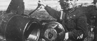
In 1904, he received a patent for “Method of signaling distant objects using electric waves”[2]. But different countries traditionally honor different inventors of radar. In general, her idea for a long time (from the moment the effect was discovered) was not translated into practical activity. The first practical application of radar was implemented in 1932 in the USSR in the Rapid installation. (Appendix No. 2) The world's first radars, adopted for service and mass-produced, were in the USSR in 1939.
USSR
In the Soviet Union, awareness of the need for aircraft detection means free from the disadvantages of sound and optical surveillance led to the development of research in the field of radar. The idea proposed by the young artilleryman P.K. Oshchepkov received the approval of the high command: the People's Commissar of Defense of the USSR K.E. Voroshilov and his deputy, M.N. Tukhachevsky.
In 1932, on the basis of the Leningrad Institute of Physics and Technology, the Leningrad Electrophysical Institute (LEFI) was created under the leadership of A. A. Chernyshev, where research and development work on radar was carried out. In 1935, LEFI was disbanded, and on its basis the “closed” institute NII-9 was organized with defense topics, including radar. Its scientific leader was M.A. Bonch-Bruevich. Work on radar was also started at the UPTI in Kharkov. By the beginning of the war, through the efforts of scientists and engineers from LEFI, NII-9 and other organizations, experimental ground-based radar stations were created.
On January 3, 1934, an experiment was successfully carried out in the USSR to detect an aircraft using the radar method. The plane, flying at an altitude of 150 meters, was detected at a distance of 600 meters from the radar installation. The experiment was organized by representatives of the Leningrad Institute of Electrical Engineering and the Central Radio Laboratory. In 1934, Marshal Tukhachevsky wrote in a letter to the USSR government: “Experiments in detecting aircraft using an electromagnetic beam confirmed the correctness of the underlying principle.” The first Rapid pilot plant was tested in the same year.
The transmitter was installed on the roof of house No. 14 on Krasnokazarmennaya Street, Moscow, the receiver was installed in the area of the village of Novogireevo; M. N. Tukhachevsky, N. N. Nagorny, M. V. Shuleikin were present. The equipment was demonstrated by P.K. Oshchepkov. In 1936, the Soviet centimeter radar station "Storm" detected the aircraft from a distance of 10 kilometers. The first radars in the USSR, adopted by the Red Army and mass-produced, were: RUS-1 - from 1939 and RUS-2 - from 1940.
On July 4, 1943, in accordance with the State Defense Committee Resolution No. 3686ss “On Radar,” the Radar Council under the State Defense Committee was formed. Its initiators were military engineer M. M. Lobanov and scientist A. I. Berg.
Great Britain
Prime Minister Churchill's science adviser, Professor F. A. Lindemann, summed up the development of the H2S radar bombsight: "It's cheap." Meanwhile, the H2S gave the British bomber force not only a sight for bombing in limited visibility, but also a navigation aid.[4]
The installation of radar fuses in shells reduced by an order of magnitude the consumption of the number of shells required to shoot down one V-1 aircraft and the intensity of such raids decreased significantly. By the beginning of the Second World War, the Chain Home radar station system was deployed in Great Britain. (Appendix No. 3) The history of the creation of radar stations is shown in the British documentary The Secret War: “To See A Hundred Miles.”
Germany
To protect cities from bomber raids, the Germans used anti-aircraft batteries controlled by gun guidance stations (SON) of the Wurzburg type. Allied intelligence determined that the carrier frequency of these stations was 560 megahertz. In the summer of 1943, bombers of the American 8th Air Force were equipped with Carpet type transmitters. The transmitters emitted interference - a spectrum of frequencies with an average frequency of 560 megahertz. In October 1943, the first result was summed up: two times fewer aircraft with the Carpet were shot down than without it.
From the history of radar and electronic warfare
The origin and development of radar dates back to a later pre-war period than radio communications. And, nevertheless, the armies of the countries of the fascist bloc, as well as England, the USA and the Soviet Union, by the beginning of World War II were armed with radars for various purposes, providing primarily air defense. Thus, the German air defense system used long-range detection radars for air targets "Freya" (range up to 200 km) and "Greater Wurzburg" (range up to 80 km), as well as anti-aircraft artillery gun guidance radar "Little Wurzburg" (range up to 40 km). Somewhat later, powerful stationary radars of the Wasserman type were put into operation (range up to 300 km). The presence of these funds made it possible by the end of 1941 to create a fairly harmonious air defense radar system, consisting of two belts. The first (external) began at Ostend (110 km northwest of Brussels) and stretched to Cuxhafen (100 km west of Hamburg). The second (internal) went from the northeastern border of France along the German-Belgian border and ended at Schleswig-Holstein. With the entry into service of the Mannheim-type anti-aircraft artillery fire control radar (range of up to 70 km) in 1942, additional posts began to be installed between these two zones. As a result, by the end of 1943, a continuous air defense radar field was formed.
As the war progressed, England built a network of stations along the south coast and then along the entire east coast.
This is how the Chain Home line came into being. However, German intelligence soon revealed not only the location, but also the main parameters of this network. In particular, it was found that the radiation patterns of English radars in relation to the surface of the earth (sea) make a certain angle, forming blind areas in the detection system. Using them, fascist aviation approached the coast of England at low altitudes. The British had to create an additional radar line that provided a low-altitude field. Thanks to the created system, which worked in close cooperation with other types of reconnaissance, the British were able to timely detect enemy aircraft, scramble fighter aircraft and alert anti-aircraft artillery. At the same time, the need for continuous air patrols was eliminated, as a result of which fighter-interceptors were used with greater efficiency. The losses of Nazi aviation increased sharply. Thus, only on September 15, 1940, the Germans lost 185 aircraft out of 500 that took part in the raid. This forced them to switch mainly to night raids.
At the same time, a search began for ways and means to make it difficult for enemy radar to detect aircraft in the air. A solution to this problem was found in the use by aviation of passive and active interference with radar equipment.
Passive jamming was first used by the crews of British bombers during a raid on Hamburg on the night of July 23-24, 1943. Metallized tapes (aluminum foil), called “Window”, packaged in special cassettes (packs), were dropped from aircraft and “clogged” the screens of enemy stations. In total, approximately 2.5 million cassettes, 2 thousand tapes each, were used in the raid on Hamburg. As a result, instead of 790 bombers participating in the raid, German operators counted thousands of aircraft, unable to distinguish real targets from decoys, which disrupted the fire control of anti-aircraft batteries and the actions of their fighter aircraft. The impact of interference on anti-aircraft artillery radars was particularly successful. The overall effectiveness of German air defense after the start of large-scale use of passive jamming decreased by 75%. The losses of British bombers were reduced by 40%.
To distract and exhaust air defense forces, aviation sometimes imitated false massive raids on diversionary directions with passive interference. For example, on the night of August 18, 1943, during a raid on the Peenemünde missile center, the British undertook a diversionary maneuver: several Mosquito aircraft, using passive jamming cassettes, simulated a massive raid on Berlin. As a result, a significant part of the fighter aircraft from airfields in Germany and Holland was scrambled to meet the jamming aircraft. At this time, aviation operating along Peenemünde encountered almost no opposition from enemy air defense systems.
Passive jamming tools have been constantly improved. Thus, to jam aircraft radars, anti-aircraft artillery shells filled with passive reflectors were used. Suppression of ground and ship radars was carried out using missiles equipped with Window. Sometimes, instead of foil cassettes, aircraft towed special metal nets, which represented decoys for operators of fire control and aircraft guidance stations. German aviation first used passive jamming in August 1943, during raids on British targets and ships off the coast of Normandy.
The next step in the development of anti-radar means was the use by the warring parties of active jamming, i.e., special electromagnetic radiation that suppresses radar receiving devices.
Aircraft jammers of the Carpet type were first used by Anglo-American aviation in October 1943 during raids on Bremen. By the end of that year, all B-17 and B-24 heavy bombers of the 8th and 15th American Air Forces operating in Western Europe were equipped with on-board active jamming transmitters. British bomber aviation was only 10% equipped with such transmitters. True, the British also had special planes - jammers, used for group cover for squads of planes. According to foreign press reports, before the use of radio interference, German air defense spent an average of about 800 anti-aircraft shells on one downed bomber, but under conditions of exposure to active and passive interference on the radar - up to 3000.
Against airborne radar bomb sights (reconnaissance and targeted bombing radars), active jammers and corner reflectors were most successfully used in combination. For example, the Germans learned that during night raids on Berlin, bombers use the Weissensee and Mügelsee lakes, located near the city, as radar-contrast landmarks. After numerous unsuccessful experiments, they managed to change the coastal contours of lakes using corner reflectors mounted on floating crosses. In addition, false targets were created that imitated real targets, which Allied aircraft often bombed. For example, during the radar camouflage of the city of Küstrin, the corner reflectors were placed in such a way that characteristic images of cities, the distance between which was 80 km, were observed on the screens of aircraft radars.
The combat experience accumulated during the war by air defense and air force troops showed that when conducting electronic warfare, the greatest effect is achieved with the sudden, massive and complex use of means and methods of suppressing radar. Characteristic in this regard is the organization of electronic warfare during the Anglo-American landing on the Normandy coast in 1944. The influence on the German radar system was carried out by the forces and means of the Allied air, naval, airborne and ground forces. To create active jamming, they used about 700 aircraft, ship and ground (vehicle) transmitters. A week before the landing of the expeditionary forces, most of the German radars discovered by all types of reconnaissance were subjected to intense bombardment. The night before it began, a group of aircraft with jamming transmitters patrolled along the coast of England, suppressing German early warning radars. Immediately before the invasion, air and artillery strikes were carried out on radar posts, as a result of which over 50% of the radar was destroyed. At the same time, hundreds of small ships and vessels headed in small groups towards Calais and Boulogne, towing metal-coated balloons and floating corner reflectors. The ship's guns and missiles fired metallized ribbons into the air. Passive reflectors were dropped over the moving ships, and a group of bombers, under the cover of interference, simulated a massive raid on Berlin. This was done with the aim of disrupting the work of the surviving radar surveillance system and misleading the German command about the true location of the landing of the Allied forces.
In the main direction of the landing, British bombers with jamming transmitters suppressed German radars and threw out smoke bombs to make it difficult for the enemy to visually observe. At the same time, air strikes were carried out on large communications centers in the landing area, and airborne sabotage groups destroyed many wire lines. Jamming transmitters were installed on 262 ships (from a landing barge to a cruiser inclusive) and on 105 aircraft, which practically paralyzed the operation of German radars of all types.
When the Anglo-American troops were conducting active offensive operations, the need arose to use radar to organize interaction between ground forces and aviation. The difficulty was that radios, missiles, signal panels, tracer shells and other means by which interaction was carried out in the first period of the war could ensure coordinated actions of ground troops and aviation only under conditions of good visibility. The technical capabilities of aviation already at that time made it possible to use it at almost any time of the day or year, in any weather conditions, but only with the appropriate navigation equipment.
The first attempts to partially use radar to ensure continuous interaction between ground forces and aircraft were made by the Americans during operations in North Africa. However, they managed to create a radar interaction system only at the beginning of the invasion of the European continent.
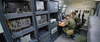
Organizationally, such a system was built on the use of a group of stations that performed various functions depending on their type. It included one MEW long-range detection station (range up to 320 km), three or four TRS-3 short-range detection stations (range up to 150 km) and several SCR-584 aircraft guidance stations for ground targets (range up to 160 km) . The MEW station as an operational information center was provided with telephone, telegraph and VHF radio communications with all radar and visual observation posts, as well as with the aviation headquarters, whose function included making decisions on the current air situation and leading air units. The SCR-584 station brought the aircraft directly to the target area, making target search much easier. In addition, each radar system had a VHF radio station for communication with aircraft in the air.
A more difficult task than the use of radar to ensure interaction between ground troops and supporting aircraft was the use of radar to detect ground targets and firing enemy artillery (mortar) batteries. The main difficulty lay in the very principle of operation of the radar - the reflection of emitted electromagnetic energy from all objects encountered along the path of its propagation. And yet, the Americans managed to adapt the SCR-584 gun guidance stations for monitoring the battlefield. They were included in the general artillery surveillance system and provided reconnaissance of ground moving targets in moderately rough terrain to a depth of 15-20 km. The share of ground-based radar detection, for example, in corps artillery, accounted for about 10%, in divisional artillery - 15-20% of the total number of explored targets.
Covered artillery and mortar positions were first discovered by radar during fighting on a bridgehead in the Anzio area (Italy) in 1943. The use of radar for these purposes turned out to be a more effective method than sound-metric and visual observation, especially in conditions of intense shelling and rugged terrain. By marking the flight path of a projectile (mine) from several directions on radar indicators, it was possible to determine enemy firing positions with an accuracy of 5-25 m and organize counter-battery warfare. First, the SCR-584 and TPS-3 stations were used, and then a modified version of the latter - TPQ-3.
The relatively successful use of radar by the Americans for ground reconnaissance is explained primarily by the fact that the Germans had absolutely no idea that the enemy would use these means for these purposes. Therefore, they did not take the necessary countermeasures, although they had experience in conducting electronic warfare in the air defense system, in the Air Force and Navy.
In the Soviet armed forces, radar and electronic warfare systems were used by air defense forces, aviation and the navy. The ground forces used mainly radio reconnaissance and radio communication jamming equipment. The first radar for detecting air targets in the surveillance, warning and communications forces was the RUS-1 (Rhubarb) station, which was put into service in September 1939 and first used during the Soviet-Finnish War. By the beginning of the Great Patriotic War, 45 sets of RUS-1 were manufactured, which subsequently operated in the air defense system of Transcaucasia and the Far East. During the war with the Finns on the Karelian Isthmus, the RUS-2 (Redut) long-range detection radar was combat tested and adopted by the air defense forces in July 1940.
It should be noted that the RUS-2 station had high technical characteristics for that time, but tactically did not fully satisfy the requirements of the troops: it had a two-antenna system, bulky and complex rotation drives. Therefore, only an experimental batch was delivered to the troops in the expectation that the single-antenna version of this station, called RUS-2s (“Pegmatite”), had passed field tests and was to be launched into series.
In the development of domestic radar, the creation of stations of the RUS-2 type compared to the RUS-1 was a significant step forward, which radically influenced the effectiveness of air defense. By receiving data on the air situation (range, azimuth, flight speed, group or single target) from several stations, the command of the air defense zone (region) had the opportunity to assess the enemy and optimally use weapons.
By the end of 1942, two prototypes of gun guidance stations called SON-2 and SON-2a were created, and in 1943 their serial production began. SON-2 stations played a very positive role in anti-aircraft artillery combat operations. Thus, according to reports from the 1st, 3rd, 4th and 14th Corps, 80th and 90th Air Defense Divisions, when firing using these stations, 8 times less shells were spent for each enemy aircraft shot down than without the stations. In terms of simplicity of design and reliability of operation, production cost and transportation conditions, as well as the time required for folding and deployment, domestic radars were superior to German, English and American ones created in the late 30s and early 40s.
The formation of radio engineering units began with the creation of the first radar unit near Leningrad in the fall of 1939. In May 1940, the 28th radio regiment was formed in Baku, in March-April 1941 - the 72nd radio battalion near Leningrad and the 337th radio battalion near Moscow. Radar technology was successfully used not only in the air defense of Moscow and Leningrad, but also in the defense of Murmansk, Arkhangelsk, Sevastopol, Odessa, Novorossiysk and other cities. In 1942-1943. so-called “high-altitude” attachments (VPM-1, -2, -3) were made for the RUS stations to determine the height of targets, as well as devices for identifying air targets using the “friend or foe” system, which made it possible to use them for guidance fighter aircraft against enemy aircraft. In 1943 alone, according to radar data, the number of fighter aircraft targeting in the air defense forces covering front-line installations increased from 17% to 46%.
A great achievement of Soviet radar was the creation of aircraft stations of the Gneiss series for detecting and intercepting air targets. In 1943, these stations were equipped with aircraft of the first heavy night interceptor division in the history of World War II. The Gneiss-2m radar was also successfully used on torpedo bombers of the Baltic Fleet. In parallel with the creation of aircraft interception stations, the development of radar sights was carried out. As a result, interception and targeting radars were created (there were only interception radars abroad) for air targets, as well as a radar bomb sight, which made it possible to carry out precise bombing against ground targets in any conditions, day or night.
When striking enemy targets, our bomber aircraft also used passive radio interference to suppress its radar for long-range detection of air targets, target designation, and targeting of anti-aircraft artillery and fighter aircraft. As a result of the enemy's massive use of radar in anti-aircraft artillery and night fighters, the losses of our bombers increased. This necessitated the need to organize counteraction to the enemy's radar system. When approaching the radar detection zone, our aircraft moved to low altitudes, taking advantage of “gaps” in the enemy radar radiation patterns. In the target area, they gained a given altitude, changed direction and flight speed. Such a maneuver, as practice has shown, led to a violation of the calculated data of the fire control devices of anti-aircraft batteries and the disruption of attacks by enemy fighters. As they approached the radar zone, the bomber crews threw out metallized tapes, which created passive interference with the enemy's radar. In each air regiment, 2-3 aircraft were allocated to create interference, which flew above and ahead of the strike groups. As a result, the ejected tapes, while descending, hid the latter from radar detection.
The continuous development of radar and electronic warfare means and methods during the Second World War had a significant impact on the methods of combat operations and the effectiveness of the air defense forces, air force, navy and ground forces of the parties. During the war, the scale of use of ground, ship and aircraft radar equipment and jamming equipment constantly grew, and the tactics of their combat use developed and improved. These processes were characterized by a double-edged struggle between the parties, which began to be called abroad in the post-war period “radio war”, “war on the air”, “radar war” and “electronic war”.
Sources: Boltunov M. “Golden Ear” of military intelligence. M.: Veche, 2011. P.66-71, 88-102, 114-117. Lobanov M. The beginning of Soviet radar. M.: Soviet radio, 1975. 144-146. Nazarenko V. Some issues of the development of means and methods of radar and electronic warfare in the Second World War // VIZH. 1982. No. 3 P.46-50. Gordienko V. A century of electronic warfare // Independent Military Review. April 11, 2003 Paliy A. Electronic warfare in wars and armed conflicts. M.: VAGS, 2007, pp. 64-72. Klimovich E., Gladkov A. From the history of domestic radar // Equipment and weapons. 2007. No. 8. pp. 2-5.
Types of radar
The nature of the target's electromagnetic radiation allows us to talk about several types of radar:
Passive radar examines its own radiation (thermal, electromagnetic, etc.), which generates targets (missiles, airplanes, space objects).
Reception of passive radar radio waves emitted by the earth and water surfaces is used to remove a radar map of the area for navigation purposes or survey the area for the purpose of reconnaissance, as well as to detect individual objects with intense radio emission.
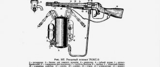
Such a radar has a radio receiver and an antenna with a narrow, needle-shaped radiation pattern that scans in a given sector. The received signals, after processing in the receiver, are sent to an electron beam indicator, in which the image scan is synchronized with the movement of the antenna radiation pattern. On the indicator screen a picture of the thermal radio emission of the area is obtained. (Appendix No. 4.5)
Active with active response is carried out if the object is equipped with its own transmitter and interaction with it occurs according to an algorithm. (Appendix No. 5)
Active with passive response involves the study of a secondary (reflected) radio signal. The radar station in this case consists of a transmitter and a receiver. (Appendix No. 5)
Semi-active radar is a special case of active radar, in the case where the reflected radiation receiver is located outside the radar (for example, it is a structural element of a homing missile).
Basics of radar in the modern world
Key words: radar, radar stations, aperture
Radar is a field of science and technology that deals with the detection and recognition of objects using radio waves and determining their various properties, such as location and movement parameters in space.
Radar stations are used to obtain images of the earth's surface using sensors operating in different ranges of the electromagnetic spectrum.
Radar stations have a significant advantage over similar technologies, such as radiometers related to passive sensors [2]:
– Independence of the obtained data from weather conditions and time of day.
– Possibility of wide visibility over long ranges with high resolution.
– Ease of managing and changing station parameters, such as the position and size of the viewing area, resolution and form of information presentation.
The principle of operation of radars is the scattering of radio waves by objects with electrical characteristics that differ from the corresponding characteristics of the environment. The intensity of radio wave scattering depends on the difference in the electrical characteristics of the medium and the object, the shape of the object, the ratio of the size of the object and the wavelength, the polarization of the radio wave, and more.
Using a receiving antenna and a receiving device, you can receive part of the scattered signal, process it, convert and amplify it. The design of the simplest radars includes a transmitter that generates and transmits a radio wave, a transmitting antenna that emits these radio waves, a receiving antenna for reflected signals, a radio receiver that amplifies and converts the signals, and an output device that processes the reflected signals. [1]
Types of radars and radar systems.
Based on the principle of operation, radar is divided into three types: active, active with active response and passive. Each of them is responsible for the method of receiving a signal reflected from an object.
Active radar (Fig. 2, a) is characterized by the fact that the detected object is not a source of radio signals. In stations operating on this principle, the transmitter generates a signal with which the antenna irradiates the target. The receiver catches the reflected signal, converts it and transmits it to the output device, which measures and calculates the coordinates to the object.
Active radar with an active response (Fig. 2, b) differs from the previous type in that the detected object is equipped with a transponder. Thus, the radar transmitter generates a signal and, with the help of an antenna, irradiates the desired object. There is a signal receiver on this object, upon receipt of which a response signal is generated, sent by the object’s transmitter back to the radar. This type of radar has some undeniable advantages over the previous type, such as:
– Increased noise immunity of the information transmission line due to encoding of requests and responses.
– Possibility of transmitting additional information
– Increasing the range due to the complication of the radar
The last type is passive radar (Fig. 2, c), characterized by solving the problem of searching for an object emitting radio waves. In this case, two situations occur: when an object emits radio waves using an installed radio transmitter, the signals of which are picked up by a passive radar station, and when the natural radiation of an object, which occurs when its temperature is above absolute zero or when its temperature contrasts with the environment, is received. This type of radar has such advantages as simplicity and high noise immunity.
In turn, radar systems are also divided into different types according to the nature of the placement of parts of the equipment in space. They are divided into single-position, bistatic (two-position) and multi-position.
Single-position radars are characterized by the fact that the entire complex is located in one place and cannot be separated. They can be implemented in both active and passive forms of radar.
Bistatic systems are determined by the fact that the transmitter module and the receiver module are located at different points in space and are based on an active type of radar.
Multi-position radars generally combine single-position, bistatic and passive stations located at different points in space. They themselves are divided depending on the use of phase information into spatially coherent, with short-term spatial coherence and spatially incoherent.
The last two types are characterized by spaced radar, i.e. they can function both jointly and separately, since their equipment is separated in space.
Synthesis of radar images
Modern radars are often used in space satellites to obtain images of the earth's surface, regardless of weather conditions and time of day. Therefore, the task is to synthesize an image depending on the received reflected signals.
Rice. 3. View of the radar surface survey diagram from the space platform
As a rule, radars installed on board an orbital platform operate in pulse mode, when the transmitting and receiving antennas are combined and alternately emit and receive signals perpendicular to the direction of flight. The signal itself for image synthesis is used in the form of a sequence of short pulses passing along the surface of the viewing area from the near to the far edge. The resolution is determined by the width of the spectrum of the probing pulses. The image is scanned in the time interval between sending a signal and receiving a response from the earth's surface.
For different types of radars, the principles of image formation are significantly different: they are different for coherent and incoherent types.
Spatial coherence is understood as the ability to maintain a rigid phase relationship at different positions. When the signal is incoherent, the radar processes the signal after receiving it, but before combining it at the information processing point.
Therefore, non-coherent radars that detect only the amplitude of the signal reflected from the ground receive a response from the ground along the entire range track together.
In the modern world, coherent synthetic aperture radars are used for detailed surveying. In such devices, not only the amplitude of the reflected signal is recorded, but also its phase. The set of impulse responses recorded during the passage of the satellite with the antenna in orbit is considered as an electromagnetic field on the aperture of the synthesized antenna. The process of processing these signals is called aperture synthesis. It allows you to repeatedly narrow the width of the antenna beam, which improves the azimuth resolution and detail of the radar image of the area. Aperture synthesis is used to obtain a radar map, reconnaissance of the radar situation and other situations. The quality of these maps is comparable to aerial photographs, but they do not depend on weather conditions and time of day.
Literature:
- Bakulev P. A. Radar systems. Textbook for universities. - M.: Radio engineering, 2004, - 320 p.
- I. V. Elizavetin, Theory of radar space photography and processing of radar images.
Methods, equipment, operating modes of radar
Primary radar
Primary (passive response) radar primarily serves to detect targets by irradiating them with an electromagnetic wave and then receiving reflections (echoes) from the target. Since the speed of electromagnetic waves is constant (the speed of light), it becomes possible to determine the distance to the target based on the measurement of various parameters as the signal propagates.
A radar station is based on three components: a transmitter, an antenna and a receiver.
The transmitter (transmitting device) is the source of the electromagnetic signal. It can be a powerful pulse generator. For centimeter range pulsed radars, it is usually a magnetron or a pulse generator operating according to the following scheme: the master oscillator is a powerful amplifier, most often using a traveling wave tube (TWT) as a generator, and for meter range radars a triode lamp is often used.
Radars that use magnetrons are incoherent or pseudo-coherent, unlike TWT-based radars. Depending on the method of range measurement, the transmitter operates either in pulse mode, generating repeating short powerful electromagnetic pulses, or emits a continuous electromagnetic signal.
The antenna radiates the transmitter signal in a given direction and receives the signal reflected from the target. Depending on the implementation, the reflected signal can be received either by the same antenna or by another, which can sometimes be located at a considerable distance from the transmitting one. If transmission and reception are combined in one antenna, these two actions are performed alternately, and to prevent the transmitter’s powerful signal from leaking into the receiver, a special device is placed in front of the receiver to close the receiver input at the moment the probing signal is emitted.
The receiver (receiving device) performs amplification and processing of the received signal. In the simplest case, the resulting signal is fed to a beam tube (screen), which displays an image synchronized with the movement of the antenna.
Different primary type radars are based on different methods for measuring the parameters of the reflected signal:
Frequency method
The frequency range measurement method is based on the use of frequency modulation of emitted continuous signals. In the classical implementation of this method (chirp), over a half-cycle the frequency changes linearly from f1 to f2. Due to the delay in signal propagation, the difference in frequencies of the emitted and received signals is directly proportional to the propagation time. By measuring it and knowing the parameters of the emitted signal, you can determine the range to the target.
Advantages:
- allows you to measure very short ranges;
- a low-power transmitter is used.
Flaws:
- two antennas are required;
- deterioration in the sensitivity of the receiver due to leakage through the antenna into the receiving path of the transmitter radiation, subject to random changes;
- high requirements for linearity of frequency changes.
Phase method
The phase (coherent) radar method is based on isolating and analyzing the phase difference between the sent and reflected signals, which arises due to the Doppler effect when the signal is reflected from a moving object. In this case, the transmitting device can operate both continuously and in pulse mode. The main advantage of this method is that it “allows you to observe only moving objects, and this eliminates interference from stationary objects located between the receiving equipment and the target or behind it”[12].
Since ultrashort waves are used, the unambiguous range of range measurement is on the order of several meters. Therefore, in practice, more complex circuits are used, in which two or more frequencies are present.
Advantages:
- low-power radiation, as undamped oscillations are generated;
- accuracy does not depend on the Doppler frequency shift of the reflection;
- a fairly simple device.
Flaws:
- lack of range resolution;
- deterioration in the sensitivity of the receiver due to penetration through the antenna into the receiving path of the transmitter radiation, subject to random changes.
Pulse method
Modern tracking radars are built as pulse radars.
Pulse radar transmits the transmit signal only for a very short time, in a short pulse (usually about a microsecond), after which it goes into receive mode and listens for the echo reflected from the target while the radiated pulse propagates through space. Since the pulse travels far from the radar at a constant speed, there is a direct relationship between the time elapsed from the moment the pulse is sent until the echo response is received and the distance to the target. The next pulse can be sent only after some time, namely after the pulse comes back (this depends on the radar detection range, transmitter power, antenna gain, receiver sensitivity).
If the pulse is sent earlier, the echo of the previous pulse from a distant target may be confused with the echo of a second pulse from a close target. The time interval between pulses is called the pulse repetition interval; its reciprocal is an important parameter called pulse repetition frequency. Long-range low-frequency radars typically have a repetition interval of several hundred pulses per second. The pulse repetition rate is one of the distinctive features by which remote determination of the radar model is possible.
Advantages of the pulse range measurement method:
- the ability to build a radar with one antenna;
- simplicity of the indicator device;
- Convenience of measuring the range of several targets;
- simplicity of emitted pulses, lasting a very short time, and received signals.
Flaws:
- the need to use high transmitter pulse powers;
- inability to measure short ranges;
- large dead zone.
Secondary radar
Secondary radar is used in aviation for identification. The main feature is the use of an active transponder on aircraft.
The operating principle of the secondary radar is somewhat different from that of the primary radar. The Secondary Radar Station is based on the following components: transmitter, antenna, azimuth marker generators, receiver, signal processor, indicator and aircraft transponder with antenna.
The transmitter is used to generate request pulses in the antenna at a frequency of 1030 MHz.
The antenna serves to emit request pulses and receive the reflected signal. According to ICAO standards for secondary radar, the antenna emits at 1030 MHz and receives at 1090 MHz.
Azimuth mark generators are used to generate azimuth marks. For one revolution of the radar antenna, 4096 small azimuth marks (for old systems) or 16384 improved small azimuth marks (English Improved AzimuthChangepulse, IACP - for new systems) are generated, as well as one North mark. The north mark comes from the azimuth mark generator when the antenna is in such a position when it is directed to the North, and small azimuth marks are used to count the antenna rotation angle.
The receiver is used to receive pulses at a frequency of 1090 MHz.
The signal processor is used to process received signals.
The indicator is used to display processed information.
An aircraft transponder with an antenna serves to transmit a pulsed radio signal containing additional information back to the radar upon request.
The principle of operation of the secondary radar is to use the energy of the aircraft transponder to determine the position of the aircraft. The radar irradiates the surrounding space with interrogation pulses P1 and P3, as well as a suppression pulse P2 at a frequency of 1030 MHz.
Aircraft equipped with transponders located in the range of the interrogation beam, upon receiving interrogation pulses, if the condition P1, P3> P2 is in effect, respond to the requesting radar with a series of coded pulses at a frequency of 1090 MHz, which contain additional information about the aircraft number, altitude, and so on . The response of the aircraft transponder depends on the radar request mode, and the request mode is determined by the time interval between the request pulses P1 and P3, for example, in request mode A (mode A), the time interval between the station request pulses P1 and P3 is 8 microseconds and upon receiving such a request the transponder the aircraft encodes its aircraft number in the response pulses.
In request mode C (mode C), the time interval between station request pulses is 21 microseconds and upon receipt of such a request, the aircraft transponder encodes its altitude in the response pulses. The radar can also send a request in a mixed mode, for example, Mode A, Mode C, Mode A, Mode C. The azimuth of the aircraft is determined by the antenna rotation angle, which, in turn, is determined by counting small azimuth marks .
The range is determined by the delay of the received response. If the aircraft is in the range of the side lobes, and not the main beam, or is located behind the antenna, then the aircraft transponder, when receiving a request from the radar, will receive at its input the condition that pulses P1, P3
The signal received from the transponder is processed by the radar receiver, then goes to the signal processor, which processes the signals and provides information to the end user and (or) to the control indicator.
Pros of a secondary radar:
- higher accuracy;
- additional information about the aircraft (board number, altitude);
- low radiation power compared to primary radars;
- long detection range.
Operating mode
There are two main modes of operation of radar stations and devices.
The first is scanning the space. It is carried out according to a strictly defined system. With a sequential review, the movement of the radar beam can be circular, spiral, conical, or sectoral. For example, an antenna array can slowly rotate in a circle (azimuth) while simultaneously scanning in elevation (tilting up and down). With parallel scanning, the review is carried out by a beam of radar beams. Each has its own receiver, and several information flows are processed at once. The tracking mode implies that the antenna is constantly aimed at the selected object. To rotate it in accordance with the trajectory of a moving target, special automated tracking systems are used.
How does radar work?
Location is the method (or process) of determining the location of something. Accordingly, radar is a method of detecting an object or object in space using radio waves that are emitted and received by a device called a radar or radar.
The physical principle of operation of a primary or passive radar is quite simple: it transmits radio waves into space, which are reflected from surrounding objects and return to it in the form of reflected signals. By analyzing them, the radar is able to detect an object at a certain point in space, as well as show its main characteristics: speed, altitude, size. Any radar is a complex radio device consisting of many components.
Any radar consists of three main elements: a signal transmitter, an antenna and a receiver. All radar stations can be divided into two large groups:
- pulse;
- continuous action.
The pulse radar transmitter emits electromagnetic waves for a short period of time (fractions of a second), the next signal is sent only after the first pulse returns back to the receiver. Pulse repetition rate is one of the most important characteristics of a radar. Low frequency radars send out several hundred pulses per minute.
The pulse radar antenna works both for reception and transmission. After the signal is emitted, the transmitter turns off for a while and the receiver turns on. After taking it, the reverse process occurs.
Pulse radars have both disadvantages and advantages. They can determine the range of several targets at once; such a radar can easily make do with one antenna; the indicators of such devices are simple. However, the signal emitted by such a radar must have quite high power. You can also add that all modern tracking radars are made using a pulse circuit.
In pulsed radar stations, magnetrons, or traveling wave tubes, are usually used as a signal source.
The radar antenna focuses and directs the electromagnetic signal, picks up the reflected pulse and transmits it to the receiver. There are radars in which the signal is received and transmitted by different antennas, and they can be located at a considerable distance from each other. The radar antenna is capable of emitting electromagnetic waves in a circle or operating in a specific sector. The radar beam can be directed in a spiral or shaped like a cone. If necessary, the radar can track a moving target by constantly pointing the antenna at it using special systems.
The functions of the receiver include processing the received information and transmitting it to the screen from which it is read by the operator.
In addition to pulsed radars, there are also continuous radars that constantly emit electromagnetic waves. Such radar stations use the Doppler effect in their work. It lies in the fact that the frequency of the electromagnetic wave reflected from an object that is approaching the signal source will be higher than from a receding object. In this case, the frequency of the emitted pulse remains unchanged. Radars of this type do not detect stationary objects; their receiver only picks up waves with a frequency higher or lower than the emitted one.
A typical Doppler radar is the radar used by traffic police to determine the speed of vehicles.
The main problem with continuous-wave radars is their inability to determine the distance to an object, but during their operation there is no interference from stationary objects between the radar and the target or behind it. In addition, Doppler radars are fairly simple devices that only need low-power signals to operate. It should also be noted that modern continuous-wave radar stations have the ability to determine the distance to an object. This is done by changing the radar frequency during operation.
One of the main problems in the operation of pulsed radars is interference that comes from stationary objects - as a rule, these are the earth's surface, mountains, and hills. When on-board pulse radars of aircraft operate, all objects located below are “obscured” by the signal reflected from the earth’s surface. If we talk about ground-based or ship-based radar systems, then for them this problem manifests itself in detecting targets flying at low altitudes. To eliminate such interference, the same Doppler effect is used.
In addition to primary radars, there are also so-called secondary radars, which are used in aviation to identify aircraft. Such radar systems, in addition to the transmitter, antenna and receiver, also include an aircraft transponder. When irradiated with an electromagnetic signal, the transponder provides additional information about the altitude, route, aircraft number, and nationality.
Radar stations can also be divided according to the length and frequency of the wave on which they operate. For example, to study the Earth's surface, as well as to work at significant distances, waves of 0.9-6 m (frequency 50-330 MHz) and 0.3-1 m (frequency 300-1000 MHz) are used. For air traffic control, a radar with a wavelength of 7.5-15 cm is used, and over-the-horizon radars of missile launch detection stations operate at waves with a length of 10 to 100 meters.
Radar range
The maximum range of a radar depends on a number of parameters and characteristics of the station’s antenna system, the power of the emitted signal, and the sensitivity of the system’s receiver. In the general case, without taking into account power losses in the atmosphere, interference and noise.
Impact of interference:
Operation of multiple radars in the same frequency range In busy areas where multiple radars are used simultaneously (for example, seaports), frequency ranges may overlap. This results in the radar receiving a signal from another radar. As a result, additional dots appear on the screen that are striking due to their geometric regularity. The effect can be removed by switching to another operating frequency. Virtual image When a radio signal is reflected from a massive object, it may further propagate to smaller objects with subsequent reflection and entry into the radar.
Thus, the path that the signal has traveled becomes larger and a virtual image of an object appears on the screen, which is actually located in a different place. This effect must be taken into account when located near large reflective objects such as bridges, hydraulic structures and large ships. Multiple reflections When placing a radar on a large vessel, the effect of multiple reflections of the signal is possible. The radar signal is reflected from a nearby object, partly hits the radar, and partly reflects from the ship's hull.
There can be many such reflections, the amplitude decreases with each reflection and the signal will be perceived until the threshold sensitivity of the receiver is reached. Several smaller objects will be visible on the radar screen. The distance between them is proportional to the distance from the radar to the object.
Influence of noise: Influence of atmosphere
Atmospheric losses are especially large in the centimeter and millimeter ranges and are caused by rain, snow and fog, and in the millimeter range also by oxygen and water vapor. The presence of the atmosphere leads to a curvature of the propagation trajectory of radio waves (the phenomenon of refraction). The nature of refraction depends on the change in the refractive index of the atmosphere with changes in altitude. Because of this, the trajectory of radio waves is curved towards the earth's surface.
Conclusion
The appearance of radar can be considered at the turn of the 19th-20th centuries. And in fact, this field of science is a little over a century old, but its rapid development has led us to the point that we can no longer even imagine our existence without it in military terms.
With the development of society, human needs are growing more and more. Consequently, new tasks and new directions appear for radar, and hence the improvement of methods and equipment of the radar system. It will not be long before scientists and inventors lose interest in this area, which is fueled by scientific progress, on the one hand, and commercial interest, on the other.
Creating a perfect radar is a complex engineering, scientific and technical task, the implementation of which is only possible using the latest achievements in electromechanics and electronics, computer science and computer technology, and energy. According to experts, in the near future the main functional units of stations of various levels of complexity and purpose will be solid-state active phased array antennas (phased array antennas), which convert analog signals into digital ones. The development of the computer complex will make it possible to fully automate the control and basic functions of the radar, providing the end user with a comprehensive analysis of the information received. Thus, despite the fact that today radar has found its wide application in military affairs, the creation of the most modern radars requires the highest level of development of science, technology and organization, therefore the development and construction of each such radar is a significant scientific and technical achievement not only domestic, but also global scale.
Bibliography
- Modern radar. Analysis, calculation and design. Edited by Kobzarev Yu.V., M., Sov.radio, 1969 - 704 pages.
- Dulevich V.E. Theoretical foundations of radar. M., Sov.radio, 1978.
- Shirman Ya.D. Theoretical foundations of radar. M., Sov.radio, 1970.
- Yu.B. Kobzarev The first steps of Soviet radar Nature magazine, December 1985
- Internet encyclopedia. Wikipedia.
- 7. Magazine “SCIENCE AND LIFE” No. 5, 2009
- Radar site.
- Website "blog about technology".
- Magazine "National Security" No. 7, 2008.
Appendix No. 1
Radar principle
Appendix No. 2
Installation of the Rapid radar
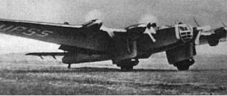
Appendix No. 3
UK radar
Appendix No. 4
Coastal maps "Chain Home"
Appendix No. 5
Types of radar: a – active with passive response; b – passive; c – active with an active response.