The development of the future Ka-25 with two promising gas turbine engines GTD-750 began long before the signing of the government decree. In March 1956, the Department of Experimental Construction of Aviation Equipment (UOSAT) of the Navy proposed to the Kamov Design Bureau to consider the possibility of creating a ship-based anti-submarine helicopter with a flight weight of 5-6 tons. Initially, it was planned to make one machine (product “D”), capable of searching for and destroying submarines of a potential enemy . In November 1957, development of the engine and gearbox began.
Ka-25 helicopter - video
The weight of the bomb load is 600 kg, and the weight of special equipment is 350-300 kg. At the same time, the diameter of the main rotors should not exceed 16 m, which made it possible to operate it from ship platforms measuring 9x10 m. The search for submarines in a submerged position was to be carried out using the Oka hydroacoustic station (OGAS) lowered to a depth of 40 m, radio hydroacoustic system "Baku" with a receiving device and discarded radio-acoustic buoys (RSAB). The helicopter should have had a radar for detecting submarines, orienting and interconnecting vehicles in a group flight, as well as equipment for receiving RGAB signals. It was possible to replace the OGAS with a magnetometer. Armament included anti-submarine torpedoes or depth charges.
Flight and navigation equipment was supposed to provide flights over a non-landmark surface and automatic piloting when flying to a target and while hovering in the search zone. For an emergency landing on water, inflatable balloons and emergency equipment for the crew were provided. The engines had to have an emergency power mode in case one of them failed. To develop a power plant in Omsk at the P.I. Baranov organized the OKB under the leadership of V.A. Glushenkova.
Two years later, the Kamov Design Bureau was given the task of creating a transport and landing version of the Ka-25, for which it was required to develop a Phalanx rocket weapon system for firing at ground targets. In addition, the helicopter's armament was to include unguided rockets TRS-212/132, KARS-160, 57 and ARS-57M and a 12.7 mm machine gun. The vehicle was ordered to be presented for joint testing with the customer in the third quarter of 1962. It was also recommended to study the issue of developing Dragon and Lotus guided missiles for the Ka-25. Looking ahead, I note that the customer’s wishes remained on paper, but at the air parade in Tushino in the summer of 1961, the Ka-25 was demonstrated with two fake brightly colored missiles. The first to be built at the Ukhtomsky plant No. 938 in the Moscow region was the resource vehicle No. 01-R, and then the target designator version No. 02-Ts. The third prototype was the PLO helicopter No. 03-B. First, the PLO helicopter (“DB”) was launched for flight testing, which took off from the ground on May 11, 1961, and the first flight of the helicopter in a circle, piloted by test pilot D.K. Efremov, - June 20 of the same year.
On November 10, 1961, a document signed by Belyansky was placed on Ponomarev’s desk, which stated that “the Ka-25 has passed the necessary development work and flight tests.” As follows from a certificate sent on August 24, 1961 to the CPSU Central Committee, “as of August 24, the Ka-25 had flown 11 hours 36 minutes. During testing, a speed of 185 km/h and a height of 1000 m were achieved. Flights were carried out with a weight of 5600 kg, and hovering near the ground with a weight of 6600 kg.
Preliminary tests of the Ka-25 with a flight weight of 6100 kg showed that with an engine power of 700 hp. the Air Force requirement for the helicopter to hover at an altitude of 50 m can be satisfied. On the Ka-25 life-saving prototype, factory tests at the 43rd hour as a result of ground resonance, due to insufficient rigidity of the landing gear struts, some fuselage components were destroyed in the transverse plane.” In 1963, a prototype of the DC helicopter was built at the Ukhtomsky Aviation Plant. Externally, it differed from its predecessor in the mechanism for folding the front landing gear, which interfered with the operation of the Initiative-2 all-round radar with an enlarged antenna radome (part of the “Success” reconnaissance and target designation complex) and the radome of the transmitting antenna of the automatic data transmission system (ASPD) under the fuselage.
In the same year, test pilot E.I. Laryushin was the first to fly a helicopter into the air, although without the “Success” equipment. Factory tests of the vehicle continued until the end of the year, and at the same time pilots from the Air Force Research Institute flew it. Later A.G. Solodovnikov said: “The helicopter had an automatic control system (ACS), which provided all flight modes up to hovering over the water surface. The crew's life support system included sea rescue suits, which ensured a person's long stay afloat at water temperatures close to zero. I was left with a good impression of the flight qualities of the Ka-25Ts. The machine is well controlled - the self-propelled guns made the helicopter stable, and the set of flight and navigation equipment made it all-weather. The cockpit is comfortable and had excellent visibility to the outside.”
In 1964, the Ka-25Ts entered joint state tests, which took place in Severomorsk on ships of the Northern Fleet, the destroyer and cruiser Grozny. Testing of helicopter and shipborne equipment continued until October 1965, and almost immediately it began to enter service with the navy under the designation Ka-25Ts, although the complex was accepted into service with naval aviation only on December 2, 1971. The Ka-25Ts could patrol at a distance of up to 200 km from the home ship. The onboard radar detected a target at a distance of up to 250 km, after which the information was transmitted to the anti-submarine ship. The Ka-25Ts were operated by the Russian Navy until the mid-1990s.
Preparations for serial production of the Ka-25 began in the fall of 1961 at plant No. 99 in Ulan-Ude. The first to be built in 1964 were three anti-submarine Ka-25s No. 04, 05 and 06 with GTD-750. They were equipped with the Initiative-2K radar, Raznobuy and Poplavok equipment, an Orsha magnetometer, a Jasmine sight, and Pero and Prospekt radio stations.
Serial production of the Ka-25 continued until 1975, during which time 460 vehicles in the PLO version and 50 target designators were built.
Modifications
Ka-25 - Basic modification, created for the purpose of testing and verifying the feasibility of implementing a helicopter that complies with the technical specifications. Subsequently, the developers transferred the entire emphasis to the Ka-25PL.
Ka-25BT - (BT - trawl towing vehicle). Modification of the Ka-25 for demining water areas from electromagnetic and acoustic mines by trawling. 12 helicopters of this modification took part in the international mine clearance operation in the Gulf of Suez.
Ka-25BShZ - (BShZ - towing cord charges). Modification of the Ka-25 for clearing water areas from bottom mines by towing cord charges. Created on the basis of a decree of May 8, 1973.
Ka-25IV - Ka-25PL, converted to measure the trajectories and coordinates of the fall of ballistic missile warheads. Built on the basis of a decree of June 18, 1962. A total of 6 copies were converted.
Ka-25ISK - Modification of the Ka-25 for the adjustment of shipborne radar stations. Created on the basis of a decree of March 10, 1971.
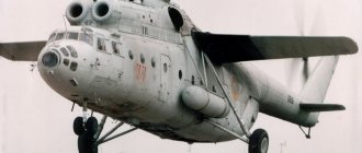
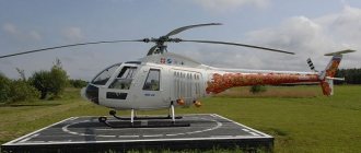
Helicopter flying crane Ka-25K USSR 1967
Ka-25K - Modification of the Ka-25 for moving cargo. The helicopter has no military equipment, and a suspended cabin for the loading operator is installed in the forward part of the fuselage, who is able to control the helicopter during loading operations. The vehicle is capable of transporting cargo weighing up to 2 tons on an external sling, and up to 1.5 tons inside the fuselage.
Ka-25L1 - (L - laboratory). Modification of Ka-25 for hydrological research.
Ka-25L2 - (L - laboratory). Modification of the Ka-25 for research and testing of lowered hydroacoustic stations. Created on the basis of a decree of May 12, 1971.
Ka-25LZ - Modification of the Ka-25 for testing new types of anti-submarine weapons. Created on the basis of a decree of October 28, 1970.
Ka-25M - Project of a multi-purpose helicopter based on the Ka-25. Was not implemented.
Ka-25PL
Ka-25PL - The main modification of the Ka-25 helicopter. The helicopter is designed to search for and destroy nuclear submarines using onboard detection and destruction equipment at a distance of about 200 km from the home ship. A total of 275 cars of this modification were produced. The helicopter is equipped with a VGS-2 Oka drop-down hydroacoustic station in the rear part of the fuselage, an Initiative-2K search radar in the nose fairing and a Baku radiohydroacoustic system with a SPARU-55 Pamir receiving device. Also, vehicles of this modification are equipped with a radio receiver for transponder beacons RPM-S, which interacts with radar buoys of the “Poplavok-1A” type. In the search version, the helicopter can carry and use up to 36 dismountable radio-acoustic buoys of the type RGB-N “Iva”, RGB-NM “Chinara” or RGB-NM1 “Zheton”, located in a container on the starboard side behind the main landing gear. The helicopter can be armed with AT-1, AT-1M, T-67 torpedoes, the APR-2 missile-torpedo or anti-submarine bombs (PLAB 250-120, -50, -MK).
Ka-25PLS - Anti-submarine helicopter for using the VTT-1 "Strizh" torpedo. Created on the basis of a decree of August 5, 1970 and adopted for service in 1976. The peculiarity of the Swift torpedo is its control by wire. The helicopter is equipped with Aist-K data transmission equipment.
Ka-25PLF - Modification of the Ka-25PL, equipped with uprated engines.
Ka-25PLE - Search helicopter obtained by converting the Ka-25PL. Created on the basis of a decree of July 10, 1967. Used to search for spacecraft that splashed down in the Indian Ocean.
Ka-25PLYU - Helicopter for combating submarines with the help of an 8F-59 depth atomic bomb, for which the bomb bay was converted to accommodate it.
Ka-25PS of the USSR Navy aviation, 1987.
Ka-25PS - Search and rescue modification of the Ka-25, created by dismantling equipment from the Ka-25PL and designed to act in the interests of the Ministry of Defense. The design of the machine began on the basis of an order of the Commission of the Presidium of the Council of Ministers of the USSR dated June 28, 1972. Special equipment was removed from the vehicle, but a winch with a lifting capacity of 250 kg, equipped with a basket for lifting people, was installed, as well as additional lighting equipment and a drive radio station for direction finding of emergency radio beacons.
Ka-25ROMB - Modification of the Ka-25 for electronic reconnaissance. Built on the basis of a contract dated 1975.
Ka-25F - Project of a front-line helicopter based on the Ka-25, equipped with a ski chassis and armed with a 23-mm cannon, NAR and ATGM units.
Ka-25Ts is a target designation helicopter designed to act in the interests of coastal or naval command posts, providing them with the coordinates of targets that are not available for direct radar detection. This modification of the helicopter was developed simultaneously with the modification of the Ka-25PL, since during the development of a single naval helicopter it turned out to be impossible to combine the functions of anti-submarine defense and target designation in one helicopter, without exceeding the established restrictions on weight and dimensions. The helicopter of this modification made its first flight on March 21, 1962. A total of 50 vehicles of this modification were built. The Ka-25Ts differs from the Ka-25PL by the installation of an all-round radar mounted in the nose cone and an automatic data transmission system. These systems are an integral part of the helicopter-ship reconnaissance and target designation complex “Success”. The helicopter is capable of patrolling waters at a distance of up to 200 km from the home ship, conducting radar patrol and target designation within a radius of 250 km, and providing relay within a radius of 250 km. The bomb bays on the helicopter were eliminated (in their place additional fuel tanks were installed) and the systems necessary for detecting submarines. The landing gear is made retractable in flight to eliminate shadowing of the radar. A winch is also mounted on board, allowing the helicopter to be used as a search and rescue helicopter. The modifications made made it possible to reduce the weight of the vehicle and increase the fuel supply, which resulted in a longer flight range and increased patrol time.
Ka-25Sh - Fire support helicopter for ground forces and amphibious assault forces. Armed with units of unguided aircraft missiles (UAR). Built on the basis of a decision of the Ministry of Defense of February 21, 1975.
Photos walk around
Photos of the Ka-25Ts helicopter were taken at the Central Museum of the Armed Forces on August 24, 2015.
1
Performance characteristics of the Ka-25
— Start of service: December 2, 1971 — Status: withdrawn from service — Units produced: ~ 460
Ka-25 crew
— 2 people
Ka-25 capacity
— 1 anti-submarine weapons operator or 12 passengers
Overall dimensions of Ka-25
— Fuselage length: 9.75 m — Main rotor diameter: 15.74 m — Tail rotor diameter: — Maximum fuselage width: 3.76 m — Height: 5.37 m
Weight of Ka-25
— Empty weight: 4765 kg — Normal take-off weight: 6970 kg — Maximum take-off weight: 7140 kg — Fuel weight in internal tanks: 1460 kg
Ka-25 engines
— Power plant: 2 × turboshaft GTD-3F — Engine power: 2 × 900 l. With. on takeoff
Speed Ka-25
— Maximum speed: 220 km/h — Cruising speed: 185 km/h — Combat radius: 200 km
Flight range of the Ka-25
— Practical range: 450 km — Ferry range: 650 km (with PTB)
Practical ceiling of Ka-25
— 4000 m
Static ceiling Ka-25
— 600 m
Dynamic ceiling Ka-25
— 4500 m
Armament of the Ka-25
— Combat load: 1100 kg — Bomb: 4 x PLAB-250-120 or 8 x PLAB-50-64 / PLAB-MK / OMAB-25-12D / OMAB-25-8N — Torpedo: 2 x AT-1/AT -1M
History of creation and production
The history of domestic aviation notes a number of long-lived aircraft, representing a fusion of design perfection, reliability and flight safety. These are the An-2, Il-14, Mi-4, MiG-21, which glorified their creators. Among them, undoubtedly, is the Ka- 25 It seems important to me, a participant in the state tests of the Ka-25 helicopter, to talk in more detail about this wonderful machine. On the eve of the celebration of the 300th anniversary of the Russian Fleet, it is appropriate to recall one of the interesting stages in the creation of our ocean-going fleet, which is closely related to the development of domestic helicopter manufacturing.
First of all, it must be said that modern warships with powerful power plants and various systems create their own noise level that does not allow reliably detecting the noise of submarines. At the same time, the noise level of nuclear submarines is due to specially implemented design solutions and application tactics taking advantage of the underwater position turns out to be so small that it allows them to win in duel situations with surface ships. The range of action of shipborne radars and other electronic systems for detecting surface targets is limited by direct visibility due to the natural curvature of the water surface.
To solve the tasks assigned to the ocean fleet, fundamentally new helicopter carrier ships were required to combat nuclear submarines and enemy surface ships. As a result, the need arose for the emergence of a new generation ship helicopter capable of solving the tasks of anti-submarine defense, reconnaissance and target designation, mine sweeping, performing rescue and other work The light naval helicopter Ka-15 could no longer meet the immeasurably increased requirements of the fleet.
The creation of the first shipborne helicopter Ka-10 (1949) and then the Ka-15 (1953) at the Kamov Design Bureau and their adaptation to ship-based deployment conditions showed that this is a complex scientific and technical problem, taking into account the experience accumulated by the OKB in this area , the Ministry of Defense entrusted him with the development and construction of a new Ka-25 helicopter, equipped with the necessary flight-navigation and search-and-sighting on-board equipment, as well as means of destroying submarines.
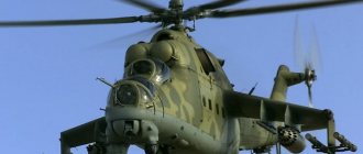
The Ka-25 naval combat helicopter made its first flight on May 20, 1961. Piloted by test pilot DK Efremov. Built at the helicopter plant in Ulan-Ude in 1965, serial samples marked the beginning of the successful flight operation of these machines. Thus, the Ka-25 is the first combat helicopter in our country. For information, the Mi-24 combat army helicopter appeared in 1969.
For the first time, the OKB had to not only build and test the Ka-25, but also ensure its compatibility with the carrier ship being simultaneously created. The ship, in turn, had to have a runway and parking areas, a flight control center. It was provided for in the inter-deck and hold volumes creation of hangars for helicopters, compartments for maintenance equipment and fuels and lubricants. It was necessary to provide comfortable accommodation for flight and engineering personnel.
In order for a helicopter carrier ship to become a truly effective combat system, the helicopter had to accommodate a modern multifunctional complex, which had no analogues at that time. Only with its help was it possible to reliably search for submarines, detect surface ships at long distances and transfer their coordinates to the ship and coastal bases — when piloting a helicopter day and night in simple and difficult weather conditions over a directionless water surface. This complex ensured the effective use of weapons for the destruction of nuclear submarines.
A ship's helicopter must have the smallest possible dimensions. This condition is best met by the coaxial scheme, on the basis of which helicopters with the “Ka” brand are designed. However, to accommodate the on-board complex on one carrier vehicle would require the creation of a large vehicle with a take-off weight of about 15,000 kg, which would be in clear contradiction with the requirements for the vehicle’s dimensions. Specialists from the Design Bureau and the Ministry of Defense were able to find a successful solution.
Photo of Ka-25
Description of design
Twin-engine helicopter with coaxial rotors and developed vertical tail.
Fuselage
The fuselage of the Ka-25 is made of D16T duralumin with a thickness of 0.8 mm and is functionally divided into two parts. The longitudinal power structure of the front part of the helicopter is represented by four power beams and two spars. The transverse power structure of the front part of the helicopter is formed by 18 frames, of which 7 are power frames. The tail boom frame is formed by two spars and eight frames, to which eighteen stringers are attached. The thickness of the tail boom skin is 3 mm. The helicopter windows are made of plexiglass 3 mm thick. The front windows are equipped with windshield wipers and are washed with an alcohol-based solution to prevent icing.
Power point
The helicopter's power plant is represented by two GTD-3F gas turbine engines with a power of 900 hp. developments of the Omsk Engine Design Bureau. Subsequently, the power of these engines was recognized as insufficient, and since 1972, helicopters began to be equipped with GTD-3M engines with a power of 1000 hp. The engines, together with hydraulic and oil systems, gearboxes and some other units, are located in a removable engine nacelle at the top of the fuselage.
Fuel system
The fuel system of the Ka-25 helicopter is represented by 8 soft fuel tanks located under the cabin floor lateral to the bomb bay, fuel pumps for various purposes and can be supplemented with two additional 200 liter tanks on the sides of the fuselage. The main tanks are grouped in pairs. On the Ka-25Ts, the tank capacity was increased due to the elimination of the bomb bay. The capacity of the main fuel tanks on the Ka-25PL and Ka-25Ts is 1105 kg and 1705 kg of kerosene, respectively.
Transmission
The helicopter's transmission is represented by a four-stage planetary gearbox RV-3F or RV-3M, located in a common nacelle with the engines in the upper part of the fuselage. The gearbox takes power from the output shafts of the turbines and sums up their power.
Support system
The helicopter's supporting system consists of two three-blade rotors with a diameter of 15.74 m, located coaxially, and a rotor column. The top screw rotates clockwise (top view), the bottom one rotates counterclockwise. The blades, 7.085 m long, have a chord of 0.37 m and consist of a hollow duralumin spar, to the trailing edge of which 19 tail sections are glued, forming a profile. The leading edges of the blades are covered with rubber. The blades are equipped with an electric anti-icing system, pneumatic alarm for cracks in the spars, balancing and anti-flutter weights. Outline lights are located on the upper propeller blades. The blade angles are controlled using the upper and lower swashplates. To save space on the deck or in the hangars of a ship, it is possible to fold the blades in a horizontal plane (to form a 22° sector) using an electrical system or manually.
Anti-icing system
Icing of the rotor blades in flight is prevented by an electric anti-icing system. The engine air intakes are heated with warm air.
Hydraulic system
Control of the orientation of the rotor blades, deflection of the rudder planes, as well as retraction and extension of the landing gear (only on the Ka-25Ts) is carried out using the helicopter’s hydraulic systems. The helicopter's hydraulic system is represented by two independent spaced systems, the main ARS-10B and the emergency ASP-10V. Direct control falls on four hydraulic boosters. Each of the systems is arranged in a single block, combining all units and installations into a single whole.
Chassis
The helicopter landing gear is four-legged, not retractable in flight (with the exception of the Ka-25Ts). The wheels of the main supports are braked, the front ones are self-orienting. The chassis base is 3.02 m. The track of the front and rear wheels is 1.41 m and 3.5 m, respectively. The diameter and width of the front and rear wheels are 400×150 mm and 600×180 mm, respectively.
The technical specifications for the development of the helicopter required landing on the deck of a ship with lateral and pitching motions of 10° and 3°, respectively, and winds of up to 18 m/s.
To ensure a safe landing in such conditions, the main landing gear legs are spaced to the sides and moved back to prevent the vehicle from tipping over onto its tail.
To compensate for horizontal vibrations (the landing platform of a ship can shift several meters horizontally during heavy rolling), the main struts are attached to the fuselage using movable trusses, which ensures the mobility of the landing gear in the horizontal plane.
The vertical component of vibrations of the landing platform (can move vertically at a speed of up to 2 m/s) is damped using a shock-absorbing strut of the main supports, consisting of high and low pressure shock absorbers connected in series. The high-pressure shock absorber absorbs overloads caused by impacts on the deck during landing, taxiing and takeoff. A low-pressure shock absorber dampens vibrations such as “ground resonance” during takeoff and landing.
To ensure an emergency landing on water, multi-section (2-section front and 4-section rear) balloons are mounted on the landing gear, which are filled with compressed air from three cylinders within six seconds. The peculiarity of filling ballonets was that the air from the cylinders, passing through the ejectors, also sucked in outside air in such a way that the ballonets were filled with outside air by 60 percent or more. The system is completely autonomous and does not depend on engine operation. However, it created significant aerodynamic drag and weighed about 260 kg. Due to the latter circumstance, as well as low efficiency during a “hard” emergency landing, balloons were removed from helicopters in the 70s.
Electrical system
The source of alternating current on the helicopter is the SGS-40U generator with a power of 40 kW, which produces a current of 208 V. In an emergency, a PT-1000TSS converter with a power of 1000 W is used, which produces a current of 36 V. Both devices produce a current with a nominal frequency of 400 Hz. DC consumers are supplied from two STG-6M starter-generators producing a current of 28.5 V and two 15-STSS-45A batteries.
Navigation, piloting, communication systems
The Ka-25 navigation equipment is represented by the ARK-9 automatic radio compass, the KI-13 magnetic compass, the VD-10 altimeter, the RV-3 low-altitude radio altimeter and the DV-15M altitude sensor. Flight parameters allow you to track the US-250 speed indicators, VAR-30-MK variometers, AGK-47-VK attitude indicators and the KS-3B heading system.
The crew also has at their disposal a central gyroscopic vertical TsGV-5, an indicator of hovering parameters UPV-2, a thermometer TNV-45 and a watch AChS-1.
The pilot’s work is facilitated by the autopilot, which, without any effort on the control stick, stabilizes the roll and pitch angles, altitude and course, and is also capable of semi-automatic damping of roll, pitch and altitude in controlled flight.
The helicopter is equipped with HF and VHF radio stations R-842 Atlas and R-860 Pero. The latter provides stable radio communication with command posts and other helicopters of the group at a distance of 100 km at a flight altitude of 1000 m. The VHF radio station R-855u “Priboi-1” is used as an emergency radio.
Crew members communicate with each other using the SPU-7 aircraft intercom.
There is also an MS-61 aircraft tape recorder and an A-39 aerial camera mounted in the tail boom. Flight data is recorded using a K2-715 barospeedograph.
Armament
The anti-submarine modification (Ka-25PL) can carry in the bomb bay and use bomb and torpedo weapons with a total mass of up to 1100 kg (the normal torpedo and bomb load is 650 kg).
The main torpedo armament of the helicopter was the AT-1 torpedo weighing 550 kg. This type of torpedo is capable of attacking a submarine at a depth of 20 to 200 m, with a speed of 25 knots. Subsequently, instead of the AT-1, its modification AT-1M began to be used.
The helicopter's bomb armament is represented by deep anti-submarine bombs PLAB-250-120, PLAB-50-64 and PLAB-MK, capable of hitting a boat at a depth of up to 300 m. It is possible to use day and night marker bombs OMAB-25-12D and OMAB- 25-8Н, located on external holders.
Inside the Ka-25
In service
- USSR - was in service until the collapse of the country in 1991
- Russia - The Ka-25Ts was in service until the mid-1990s
- Ukraine - after the division of the Black Sea Fleet in 1997, Ukraine received 28 Ka-25 (18 Ka-25PL, 2 Ka-25BSHZ, 2 Ka-25Ts, 3 Ka-25PN and 3 Ka-25U)
- Bulgaria - 4 Ka-25s were delivered from 1984 to 1991
- Vietnam - 17 Ka-25s delivered from 1979 to 1984
- Yugoslavia - 12 Ka-25s delivered in 1975
- India - 7 Ka-25 delivered in 1980
- Syria - 9 Ka-25s delivered in 1974
Modifications
Ka-252TL – Telemetry helicopter as part of the ship complex.
Ka-27E (“Sovetnik-SV”) – Radiation reconnaissance helicopter.
Ka-27M - The latest modification of the helicopter, equipped with a radar command and tactical system, which includes the following systems: acoustic, magnetometric, radio reconnaissance and radar with an active phased array antenna FH-A. The radar is installed under the fuselage and provides all-round visibility when searching and detecting surface, air and ground objects. Serial modernization of combat helicopters to the Ka-27M level was planned to begin in 2014.
Ka-27PL
Ka-27PL - Deck-mounted anti-submarine helicopter.
Ka-28 – Export version of the multi-purpose Ka-27 helicopter, with a simplified set of equipment. In the 21st century, it began to be supplied in limited quantities to parts of the RF MA, due to an acute shortage of Ka-27.
Ka-29 – Transport-combat, designed for transportation, landing and fire support of marines. It has small arms, cannons, missiles and bombs and local armoring of the cockpit.
Ka-31 – (Ka-27RLD) AWACS helicopter.
Ka-32 - Civil modification, certified according to international airworthiness standards FAR-29/FAR-33 and supplied to Canada, Malaysia, Switzerland, South Korea.
Ka-27E – Based on the Ka-27, the Ka-27E (Ka-252E “Sovetnik-SV”) was developed. The helicopter was based on the Absheron support ship and was intended to monitor ships for the presence of radioactive materials on board. According to various sources, several machines were built. Currently, the Ka-27 remains in service with the Russian Navy, and the “PS” modification is the most popular for a simple reason - the helicopter is primarily used as a transport vehicle on ships and coastal bases.
Ka-27PS
Ka-27PS – The Ka-27PS sea rescue helicopter is designed to rescue or provide assistance to the crews of ships and aircraft in distress, as well as to search for re-entry spacecraft.
The special equipment includes A-817 radio navigation equipment, designed to detect radar transponder beacons and display their location on the radar all-round display. The equipment includes a VHF antenna on the engine nacelle and a C1.7 unit on the operator’s console. The radar station coupled with the A-817 equipment received the designation “Octopus-PS”. It provides a search for splashed-down spacecraft and other objects equipped with radar beacons - transponders and marker buoys. To guide the helicopter to a given area based on signals from radio beacons, an automatic radio compass ARK-UD is installed. Radiation levels in the cockpit are measured using a DP-3B X-ray meter. The Ka-27PS is equipped with the NKV-252 navigation complex, which includes on-board radio equipment for the automated short-range navigation and landing system A-340-SV-BORT, the Greben-2 heading system, and the DISS-32 Doppler speed and drift angle meter , airspeed sensor, barometric altimeter UVID-30-15, automatic radio compass.
The Ka-27PS crew consists of four people: a commander, a navigator, a flight engineer and a rescue paramedic. The rescue paramedic has full medical and diving training; in addition, he must also be ready to winch down from a height of 50 meters (training for lowering a rescuer into the sea was nicknamed “fishing” by wits). The rescue modification of the helicopter has a characteristic coloring - white sides and wide red stripes on the belly and back of the fuselage.
The rescue helicopter has additional means of lifting, rescue and lighting. On the left side, outside the cargo door, a lifting device is installed - an SLG-300 electric winch, a turning mechanism, a boom and a hydraulic cylinder for raising and lowering the boom - with a lifting capacity of up to 300 kg. A universal or strap seat or a belt for lifting astronauts in a cradle can be attached to the lifting device. The rescue means being dropped include an NP-2A inflatable belt, two LAS-5M-3 boats, 12 PSN-6AM rafts, two marker buoys of the Prizyv-M system. The configuration of search equipment varies widely depending on the task. There is, for example, the following option: 10 life jackets, two PSN-6AM rafts, two OMAB naval orientation bombs, an additional fuel supply of 110 liters. To facilitate search and rescue at night, four PRF-4MP headlights (with a power of 1000 watts each), one FPP-7 and one FR-9 are additionally installed. In addition, it is possible to use a manual signal spotlight RSP-45. Headlights PRF-4MP and FPP-7M are used to illuminate cargo on an external sling or the area under the helicopter, FR-9 - to illuminate those being rescued; two external PRF headlights are located below along the axis of symmetry of the fuselage on both sides. Emergency radio devices consist of the Prizyv-M complex and two automatically fired radio markers to indicate the search object.
The search and rescue version can be converted into a training version by the operating organization. At the navigator's workplace, a longitudinal-transverse control handle, directional control pedals, and a collective pitch lever are installed. Instead of the 1S57 radar unit, an instructor's instrument panel with speed, altitude and course indicators, a variometer, attitude indicators - six instruments in total - is installed. When using a helicopter in the ambulance version, four stretchers with fastening straps and safety belts for the wounded are installed. Medical and sanitary equipment includes two folding stools, two 3-liter thermoses, a medical worker’s table, a set of splints, two GS-10 oxygen devices, a doctor’s bed, and a 3-liter water tank. Sanitary equipment consists of a bucket, hygiene bags, two air mattresses with pumps for filling them, army blankets, and urinals.
Ka-27PSD – The Ka-27PSD search and rescue helicopter is a further development of the Ka-27PS. It differs in that it has a maximum take-off weight increased to 12,000 kg. The chassis has been strengthened and additional fuel tanks have been installed (the total capacity of the fuel system of this helicopter has reached 4830 liters).
Links[edit]
Notes[edit]
- Jump up
↑ Taylor 1996, p. 316 - "World Air Force 1987 pg. 91". flightglobal.com. Retrieved April 5, 2013.
- "World Air Forces 1991 p. 38". flightglobal.com. Retrieved April 5, 2013.
- "World Air Forces 2013" (PDF). Flightglobal Insight. 2013. Retrieved April 7, 2013.
- "World Air Forces 2001 pg. 66". flightglobal.com. Retrieved April 5, 2013.
- "World Air Force 1987 pg. 86". flightglobal.com. Retrieved April 5, 2013.
- Jump up ↑
World Air Forces 2001 pg. 73 ". flightglobal.com. Retrieved April 5, 2013. - "World Air Force 1987 pg. 105" flightglobal.com. Retrieved April 5, 2013.
- "World Air Force 1987 pg. 67". flightglobal.com. Retrieved April 5, 2013.
- Gunston, Bill. "Encyclopedia of Russian Aviation 1875–1995." London, Osprey. 1995. ISBN 1-85532-405-9 and Chant, Cris. "Warships Today." New York, Barnes & Noble Books. 2004. ISBN 0-7607-6700-9.
Bibliography[edit]
- Gunston, Bill. "Encyclopedia of Russian Aviation 1875–1995." London, Osprey. 1995. ISBN 1-85532-405-9.
- Taylor, Michael J. H. (1996). Brassey's World Factbook of Aircraft and Systems. London, England: Brassey's. ISBN 1-85753-198-1.