Restored Soviet fighter LaGG-3.
In the late 30s and the first half of the 40s, many different aircraft were created in the USSR, but not all of them became popular among Soviet pilots. That is why, after the end of the Great Patriotic War, such machines as the Pe-3, Su-2 or Er-2 became almost unknown, they preferred not to remember them. The LaGG-3, a fighter on which high hopes were originally pinned, was also among the “losers.” In reality, it turned out to be quite controversial - after all, it was on its basis that the La-5 and La-7, which became symbols of victory, were then created. Moreover, there is every reason to assume that the LaGG-3 itself could have become an excellent fighter, but this did not happen only due to objective circumstances that were in no way dependent on its designers.
Technical description
The LaGG-3 fighter is a single-engine, single-seat, cantilever low-wing aircraft of mixed design with a retractable landing gear.
Wing
The wing is wooden, detachable, two-spar. It consisted of a center section connected to the fuselage and two consoles. The spars are made of laminated wood, the so-called delta wood - pine veneer glued with VIAM B-3 glue. Between the side members in the center section there were plywood mounts for fuel tanks, and in the front part of the center section there were wheel wells for the main landing gear. The left wing had a landing searchlight (except for 66-series vehicles), and colored navigation lights were installed on the wingtips. The wing had a biconvex asymmetrical profile NASA 23016 at the base and NASA 23010 at the tips, 16% and 10% thick. Wing sweep 6.5 degrees. Each wing had 15 ribs cut from delta wood. The wing skin is made of plywood, thickness from 2.5 to 4 mm. The surface of the wing was covered with AVRK canvas and puttied, and then polished.
LaGG-Z fighter of the 3rd production series
1. Screw VISH-61P. 2. Leveling tank. 3. Hydraulic system tank. 4. Klimovsky engine M-105P. 5. ShKAS machine gun, 7.62 mm caliber. 7. KS machine gun 12.7 mm caliber. 8. ShVAK gun ammunition. 9. Oil tank. 10. Sight PBP-1a. 11. Pshute chair. 12. Battery 12A5. 13. Oxygen cylinder. 14. Compressed air cylinder. 15. Holes for adjusting the tail wheel. 16. Rudder weight balancer. 17. Trimmer. 18. Navigation light. 19. Tail wheel. 20. Radio station RSI-4. 21. AFA-1 camera (on reconnaissance aircraft). 22. Adjustable water radiator tunnel outlet. 23. Water radiator. 24. 20-mm ShVAK cannon. 25. Fuel tank. 26. Ammunition for the BS machine gun. 27. Adjustable oil cooler channel outlet. 28. Oil cooler. 29. Venturi tube.
The main landing gear sockets were attached to the front wing spar. The ailerons of the Frieze type design were of a single-spar design. The aileron spar was a duralumin tube with a diameter of 42 mm, to which 9 duralumin ribs were attached. The leading and trailing edges of the aileron had a duralumin skin with a thickness of 0.8 mm. The surface of the ailerons is covered with AVLK-2 fabric. The ailerons are balanced, the left one is equipped with a ground-adjustable trim tab. The ailerons were deflected 24 degrees up and 25 degrees down. The flaps were slotted, metal (duralumin), double-jointed, controlled by pushers (hydraulic drive). Deflection angle is 15 degrees during takeoff and up to 60 degrees during landing. The flaps were extended in increments of VZgr (vehicles of the 35th and 66th production series of plant No. 31). The pitot tube is located in the right wing (up to the 35th production series on the leading edge, and after the introduction of slats it was moved under the wing). The Venturi tube is located at the oil cooler air intake under the fuselage cowl.
| Click image for a larger view | |
| Airplane fuselage | Airplane wing |
| a—longitudinal and transverse set; b — machine gun carriage; 1—15 — frames (72, 14, 15) — reinforced; 16 — upper spars; 17—lower spars; For, 4a, 5a, 6a, 66, 7a - rims | 1,2 — front and rear side members; 3 — stringers; 4 — ribs; 5 - caisson; 6 - sheathing (delta wood); 8, 9 — front and rear stringers, respectively; 10 — butt rib; 11 — spar belts; 12 - plywood walls |
Aircraft from the 35th production series were equipped with movable metal slats of the Handley-Page type. The slats were released using pushers. The flaps are controlled using a hydraulic system and pushers. The flaps were suspended from the wing on hinges made of piano wires. On the lower surfaces of the wings there were holes that served to equalize the pressure inside and outside the wing (up to the 35th series).
Fuselage
The fuselage consisted of a front metal frame assembled from steel tubes (wooden and metal skins), as well as a rear wooden frame forming a single structure with the tail. The rear part of the fuselage was sheathed with birch plywood, the fuselage consisted of spars and frames made of delta wood. In the rear part of the fuselage there was a service hatch (420x390 mm), which provided access to the radio station and fuel filter. The antenna mast stood on the fuselage immediately behind the cockpit. There were several types of masts, including different heights. The antenna mast was made of plywood reinforced with metal plates.
Tail
The tail unit is cantilever, the stabilizers are wooden, single-spar, with plywood sheathing. The rudder and elevators are metal with fabric covering (AVR-100 or ACT-100). The handlebars are aerodynamically and mass balanced. For aircraft of some series (from 3 to 11), the rudder was balanced only by mass. The fabric covering of the rudders was covered with putty, smoothed and painted in the colors of standard camouflage. The rudder and elevators are equipped with trim tabs, adjustable on the ground up to 17 in both directions. The rudders were driven by rods and cables. The rudder was deflected by 26 in each direction, and the elevators were deflected by 30 up and 24 down. There was a navigation light at the edge of the rudder trim tab. Beginning with the 35th production series, the aircraft were equipped with modified horizontal stabilizers and elevators.
Chassis
The landing gear is three-point, single-post, classic, with oil-pneumatic shock absorption, retractable in flight. The tail wheel is stuck in the extended position (on some series) or retractable in flight. When retracted, the tail wheel moved away and was hidden in the rear part of the fuselage. The tail wheel niche was closed with a double hatch. The dimensions of the tail wheel are 300x125 mm, the wheel was controlled on the ground. The main landing gear wheels initially had dimensions of 600x180 mm, later they were replaced by larger wheels 650x200 mm. During flight, the landing gear was retracted into niches in the direction of the longitudinal axis of the aircraft. In the retracted position, the chassis was completely covered with lids. In combat units, the covers were often removed. On some aircraft, the landing gear covers consisted of two parts. Drum brakes. In the fully retracted position, the chassis was secured with a special lock. The pilot was informed about the position of the landing gear by a light on the instrument panel, as well as a mechanical indicator on the upper side of the wing. In the event of a hydraulic system failure, the pilot could manually lower the landing gear using an emergency mechanical mechanism located in the cockpit. In an emergency, the landing gear came out under its own weight. In winter, aircraft were equipped with ski landing gear, which was retracted under the wing during flight.
Cockpit
The pilot's cabin had a canopy with a cover that moved back. The canopy did not have an emergency release mechanism; the plexiglass quickly became dull, so in combat units many pilots did not close the canopy. Sometimes the sliding cover of the lantern was simply removed. The windshield is convex, later flat. No bulletproof glass was used. Behind the pilot's seat there were two small windows, providing some visibility to the rear. The seat was stamped from a duralumin sheet, adapted for a parachute seat. Behind the chair there was an armored back with a thickness of 8.6 mm. The pilot had a set of navigation instruments assembled on the instrument panel and on the sides of the cockpit. Among others, there was a US-800A speedometer, a V-12 altimeter (66th production series), a curvimeter (UP-27), and a TE-22 tachometer. fuel level indicator BE-35 or BE-40. Airplanes could have one of two types of instrument panels, which differed in placement and number of instruments. For night flights, the cockpit could be equipped with UV illumination lamps. On the floor there was an MP rocket launcher, from which it was possible shoot through the hole in the cabin floor.
Engine
The engine is carburetor, liquid-cooled M-105P (later M-105PA and M-105PF) designed by Klimov, 12-cylinder, in-line, V-shaped. Metal screw, variable pitch VISH-61P with a diameter of 3000 mm. The radiator was located under the fuselage, where it was blown by air supplied through air intakes at the bases of the wings and discharged through a tunnel under the fuselage. The air intakes at the base of the wings could have different shapes. For example, on aircraft of the 1st production series they were oval, and on aircraft of the 3rd production series they were rectangular. The temperature of the water in the radiator could be controlled by means of louvres that restricted the air flow. The oil cooler was located under the engine, and the oil tank was located immediately behind the oil cooler.
Three gas tanks were located in the middle part of the aircraft. They were covered with a rubber gasket. One tank was located in the fuselage in front of the cockpit, and two in the center section. The total capacity of the tanks is 352 l. The tanks are made of magnesium-aluminum alloy. As fuel was consumed, the tanks were filled with cooled and dried exhaust gases. It was possible to hang two additional tanks with a capacity of 100 liters under the wings (filled to 80 liters). From the 11th production series, the aircraft had five tanks (another two in the wings) with a total capacity of 468 liters. Three-bladed propeller, metal, adjustable in flight VISH-61P with a diameter of 3000 mm or VISH-105SV. Until the 35th production series, exhaust pipes with a common manifold were used, and then exhaust pipes appeared on the aircraft, connected in pairs and without a common manifold. Aircraft of the 66th production series received exhaust pipes of the same type as those installed on the Yaki-9. Electrical equipment with operating voltage 24 V.
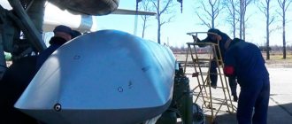
Development of the nose section of the LaGG-3 fighter
Armament
The armament of LaGG-3 aircraft up to and including the 4th production series consisted of a 12.7 mm BS machine gun firing through the propeller gearbox, two synchronized BS machine guns and two synchronized ShBAK machine guns of 7.62 mm caliber. Aircraft from the 4th to 8th (11th?) series had a 20 mm ShVAK cannon, one BS synchronized machine gun and two ShKACa. On aircraft, starting from the 12th production series, the armament was reduced to one VAK cannon and one BS machine gun. Sometimes, instead of the ShVAK cannon, a VYa-23 cannon of 23 mm caliber was installed. Several types of ammunition were used, including B-32 armor-piercing incendiary cartridges (7.62 and 12.7 mm caliber), ZB-46 armor-piercing incendiary tracer cartridges (7 ,62 mm), armor-piercing incendiary-tracer BZT (12.7 and 37 mm), incendiary O3 (20 and 23 mm). Weapon weight: from 10.5 kg (ShKAS) to 119.5 kg (NS-37), rate of fire from 782 rounds/min (ShVAK) to 900 rounds/min (VYA-23). Shot weight: 9.6-10.2 g (ShVAK), 43-49 g (BS), 96 g (ShVAK, 20 mm), 761 g (NS-37, 37 mm). Eight RO-guides were attached under the wings 82 for RS-82, RBS-82 (armor-piercing) missiles of 82 mm caliber (warhead weight 360 or 480 g), as well as MDZ-40 locks and DER-13 mounts for hanging two bombs weighing 50 or 100 kg each (for example FAB-50tsk, FAB-100M). The on-board weapon was aimed at the target using the PBP-1a sight.
| LaGG-3 fighter of various series | |
| Click on the diagram to enlarge | |
Oxygen equipment. The KPA-Zbis oxygen device, cylinder fill indicator and valves were located on the right side of the cabin. Oxygen cylinder with a volume of 4 l, operating pressure 16 MPa. The cylinder was mounted on a stand in the area of the 9th and 10th frames.
Radio station. Most often, aircraft were equipped only with the RSI-4 shortwave receiver. The vehicles of squadron and flight commanders were additionally equipped with an RSI-3 transmitter. The radio station was mounted on a special shock-absorbing rack behind the armored back of the seat, attached to the 5th and 6th frames of the fuselage.
Fighter specifications
Combat use
The first enemy aircraft appeared on the LaGG-3 account on July 13, 1941. The Do-17 bomber, not the most famous today, turned out to be shot down. It must be said that at the beginning of the war, all LaGG fighters were far from the border, and therefore were not damaged during the first battles. The largest number of such vehicles were then available in the Moscow Air Defense Forces - 75 units.
One of the front-line LaGGs in the winter of 1941-42. The mountings for the RS-82 are clearly visible under the wing.
At the end of July, LaGG-3 fighters began to arrive in units previously armed with I-16s. During the same period, a commission from the NKAP visited the front to study the first results of the combat use of the aircraft. Contrary to the “black” post-war reputation of the LaGG-3, the only noticeable criticism from the pilots was the tendency of the fighter to go into a tailspin during an energetic climb.
Nevertheless, by the fall of 1941 it was already quite clear that the Soviet aircraft was inferior to the Messerschmidt Bf-109F in almost all the most important characteristics, with the exception of horizontal maneuver. Despite this, the LaGG-3 was still much better than the outdated I-16 and easier to fly than the MiG-3. This allowed well-trained pilots to win battles with German fighters and bombers. In particular, during the defense of the skies of Moscow, pilot Grigoriev from the 178th Fighter Aviation Regiment shot down 15 enemy aircraft in a LaGG-3.
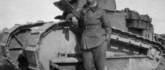
The use of LaGG-3 as an attack aircraft began in the winter of 1941-42. This was facilitated by the great “survivability” of the car, which came as a surprise even to Lavochkin himself. There were examples when Soviet pilots returned to the airfield with many holes and mutilated, half-torn off wing consoles.
Until mid-1942, the LaGG-3 remained one of the most common fighters at the front. In this regard, only Yakovlev’s aircraft competed with him. But the reputation of the fighter Lavochkin was already ruined by that time. The main reasons for this were the insufficient speed and slowness of the machine. Both shortcomings were a consequence of the LaGG-3 taking off weight being too large. His entire subsequent biography became a struggle for weight loss.
A damaged LaGG-3 after making an emergency landing.
By mid-1943, most of the surviving LaGGs were transferred to air defense units. Only 250 of these aircraft remained at the front. Despite the fact that individual pilots, and sometimes entire regiments, achieved good results flying the LaGG-3, overall this fighter was considered perhaps the worst. That is why Lavochkin’s main efforts were transferred, starting in the spring of 1942, to the creation and development of the La-5 aircraft. Its main difference from the previous model was the powerful air-cooled M-85 motor.
In the summer of 1944, production of LaGG-3 was completely stopped. A number of these aircraft took part in the war against Japan, but there were no air battles during this short conflict; everything came down to attacks on ground targets. The last LaGG-3 aircraft were written off due to wear and tear in 1947.
I-301
| I-301 | |
| Wingspan (mm) | 9810 |
| Length(mm) | 8810 |
| Height (mm) | 4400 |
| Engine | M-105P |
| Takeoff power, hp | 1020 |
| Power at altitude, hp/m 1st supercharger speed | 1100/2000 |
| Power at altitude, hp/m 2nd supercharger speed | 1050/4000 |
| Combat weight, kg | 2968 |
| Empty weight, kg | 2380 |
| Fuel weight, kg | 250 |
| Max ground speed, km/h | 515 |
| Max speed at altitude, km/h/m | 605/4950 |
| Rate of climb at the ground, m/s | — |
| Rate of climb at an altitude of 5000 m, m/s | 5,85 |
| Ceiling, m | 9600 |
| Turn time, sec | 25 |
| Range max, km | 556 |
| Run, m | 355 |
| Mileage, m | 400 |
| Armament | 1×23 2×12,7 |
Requirements for designers
After successful testing of the I-301, before launching the aircraft into mass production, the party again received a request in an orderly tone. It spoke of the need to modify the aircraft, in particular to increase its range to a thousand kilometers. It was then that the designers installed additional fuel tanks, because it was not possible to fulfill this “request” in any other way. Of course, they understood that the weight category would also increase. But along with the Yak and MiG, LaGG still became the aircraft of the new generation of the Air Force of the Soviet Army.
..715
| LaGG-3 3121715 | |
| Wingspan (mm) | 9810 |
| Length(mm) | 8810 |
| Height (mm) | 4400 |
| Engine | M-105P |
| Takeoff power, hp | 1020 |
| Power at altitude, hp/m 1st supercharger speed | 1100/2000 |
| Power at altitude, hp/m 2nd supercharger speed | 1050/4000 |
| Combat weight, kg | 3280 |
| Empty weight, kg | 2610 |
| Fuel weight, kg | 340 |
| Max ground speed, km/h | 474 |
| Max speed at altitude, km/h/m | 549/5000 |
| Rate of climb at the ground, m/s | 8,5 |
| Rate of climb at an altitude of 5000 m, m/s | 8,6 |
| Ceiling, m | 9300 |
| Turn time, sec | 20-21 |
| Range max, km | 705 |
| Run, m | 480-543 |
| Mileage, m | 450-460 |
| Armament | 1×20 1×12,7 2×7,62 |
Fighter rating
The main and, as it turned out, “ineradicable” drawback of the all-wood aircraft of Lavochkin, Gorbunov and Gudkov was the unfavorable ratio of engine power to machine weight. It was because of this that the LaGG-3 slowly gained speed, did not perform combat turns energetically enough, and often lost air duels. An experienced pilot could partially compensate for this deficiency by competently planning the battle, but averagely qualified pilots did not always cope with this task.
In addition, throughout the war, German fighters confidently surpassed the LaGG-3 in speed and therefore could dictate their terms of the fight, and in case of danger they could easily escape.
Can this shortcoming be considered a mistake by the creators of the aircraft? In part, yes - after all, the choice in favor of a heavy wooden structure was made quite consciously by them.
American heavy fighter Curtiss P-40. In terms of the ratio of engine power and take-off weight, it was inferior to the LaGG-3, but was built in large series.
But it must be taken into account that it was originally planned to install the M-106 engine on the LaGG-3, the characteristics of which were higher than those of the M-105P. Aircraft engines in general were the “bottleneck” of Soviet industry. This drawback was inherited from the Russian Empire.
In addition, the LaGG-3 should be compared not only with the La-5 or Bf-109. One can recall such a fighter as the American P-40. With an engine of comparable power to the M-105, it was even heavier than Lavochkin’s car. Meanwhile, the US industry built a total of more than 14 thousand P-40s - more than two times more than the LaGG-3 was manufactured. In other words, for some reason the Americans were satisfied with such a clumsy fighter. It was also supplied to the USSR under the Lend-Lease program.
The fact that on the basis of the LaGG-3 it was ultimately possible to create such machines as the La-5 and La-7 indicates that the original fighter was not at all as “hopeless” as it might seem. Many of the ideas incorporated into it turned out to be quite correct - for example, the exceptional efficiency of the La-5 ailerons was directly inherited from its “controversial” predecessor. Apparently, LaGG-3 should be considered a necessary stage in the natural evolution of USSR fighter aviation, without which it would not have been possible to create more advanced designs.
..855
| LaGG-Z 3121855 | |
| Wingspan (mm) | 9810 |
| Length(mm) | 8810 |
| Height (mm) | 4400 |
| Engine | M-105P |
| Takeoff power, hp | 1020 |
| Power at altitude, hp/m 1st supercharger speed | 1100/2000 |
| Power at altitude, hp/m 2nd supercharger speed | 1050/4000 |
| Combat weight, kg | 3380 |
| Empty weight, kg | — |
| Fuel weight, kg | — |
| Max ground speed, km/h | 462 |
| Max speed at altitude, km/h/m | 554/4850 |
| Rate of climb at the ground, m/s | — |
| Rate of climb at an altitude of 5000 m, m/s | 9,1 |
| Ceiling, m | — |
| Turn time, sec | |
| Range max, km | — |
| Run, m | 450 |
| Mileage, m | — |
| Armament | 1×20 1×12.7 2×7.62 8xRS-82 |
Abroad
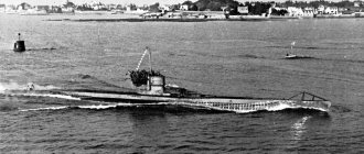
LaGG-3 was never exported. However, in 1941 - 1942. The Germans managed to capture a number of vehicles of this type in various states. There is no data on their use in the Luftwaffe, but it is known that in 1942 three of them were sold by Germany to its Finnish allies. These aircraft were operated in 1943 - 1944. squadron LeLv 32 and were used by the Finns in Karelia as short-range reconnaissance aircraft. There is a known case of a battle between a Finnish LaGG-3 and exactly the same Soviet vehicle. Long maneuvering did not bring victory to any of them. After the gun failed, the Finnish pilot left the battle.
In 1945, all three LaGG-3s were transferred to HLeLv 11 squadron. They flew there until the end of the year, after which they were decommissioned.
In the spring of 1942, one fighter was stolen from Transbaikalia to Manchuria, which was then controlled by the Japanese. The plane made an emergency landing on a field with its landing gear retracted. After repairs, the Japanese decided to test the LaGG-3. Flights began on September 29. The main characteristics of the vehicle were determined and training battles were conducted with Japanese fighters. The further fate of this aircraft is unknown.
1
..912
| LaGG-Z 31212912 | |
| Wingspan (mm) | 9810 |
| Length(mm) | 8810 |
| Height (mm) | 4400 |
| Engine | M-105PF |
| Takeoff power, hp | 1210 |
| Power at altitude, hp/m 1st supercharger speed | 1260/700 |
| Power at altitude, hp/m 2nd supercharger speed | 1180/2700 |
| Combat weight, kg | 3160 |
| Empty weight, kg | — |
| Fuel weight, kg | 350 |
| Max ground speed, km/h | 507 |
| Max speed at altitude, km/h/m | 566/3850 |
| Rate of climb at the ground, m/s | — |
| Rate of climb at an altitude of 5000 m, m/s | 6,4 |
| Ceiling, m | 10 000 |
| Turn time, sec | 21 |
| Range max, km | — |
| Run, m | 370 |
| Mileage, m | — |
| Armament | 1×20 1×12,7 |
Wing
The wing is wooden, detachable, two-spar. It consisted of a center section connected to the fuselage and two consoles. The spars are made of laminated wood, the so-called delta wood - pine veneer glued with BIIAM B-3 glue. Between the side members in the center section there were plywood mounts for fuel tanks, and in the front part of the center section there were wheel wells for the main landing gear.
There was a landing spotlight in the left half-wing (except for 66-series aircraft), and colored navigation lights were installed on the wingtips.
The wing had a NASA 23016 lenticular asymmetrical profile at the root and NASA 23010 at the tips with thicknesses of 16% and 10%. Wing sweep 6.5 degrees. Each half-wing had 15 ribs cut from delta wood. The wing skin is made of plywood, thickness from 2.5 to 4 mm. The surface of the wing was covered with AVRK canvas and puttied, and then polished.
The main landing gear sockets were attached to the front wing spar. The ailerons of the Frieze type design were of a single-spar design. The aileron spar was a duralumin tube with a diameter of 42 mm, to which 9 duralumin ribs were attached. The leading and trailing edges of the aileron had a duralumin skin with a thickness of 0.8 mm. The surface of the ailerons is covered with AVLK-2 fabric. The ailerons are balanced, the left one is equipped with a ground-adjustable trim tab. The ailerons deflected 24 degrees up and 25 degrees down.
The flaps are slotted, metal (duralumin), two-part, controlled by pushers (hydraulic drive). Deflection angle is 15 degrees during takeoff and up to 60 degrees during landing. The flaps were extended in increments of 3 degrees (vehicles of the 35th and 66th production series of plant No. 31).
The pitot tube is located in the right wing (before the 35th production series on the leading edge, and after the introduction of slats it was moved under the wing). The Venturi tube is located at the oil cooler air intake under the fuselage hood.
Aircraft from the 35th production series were equipped with movable metal handles of the Handley-Page type. The slats were released using pushers. The flaps are controlled using a hydraulic system and pushers. The flaps were suspended from the wing on hinges made from piano wires.
On the lower surfaces of the wing there were holes that served to equalize the pressure inside and outside the wing (up to the 35th series).
LaGG-3 6011
| LaGG-Z 6011 | |
| Wingspan (mm) | 9810 |
| Length(mm) | 8810 |
| Height (mm) | 4400 |
| Engine | M-105PF |
| Takeoff power, hp | 1210 |
| Power at altitude, hp/m 1st supercharger speed | 1260/700 |
| Power at altitude, hp/m 2nd supercharger speed | 1180/2700 |
| Combat weight, kg | 3006 |
| Empty weight, kg | — |
| Fuel weight, kg | — |
| Max ground speed, km/h | 545 |
| Max speed at altitude, km/h/m | 595/3400 |
| Rate of climb at the ground, m/s | — |
| Rate of climb at an altitude of 5000 m, m/s | — |
| Ceiling, m | 9400 |
| Turn time, sec | |
| Range max, km | 537-832 |
| Run, m | — |
| Mileage, m | — |
| Armament | 1×20 1×12,7 |
Distinctive feature
A distinctive feature of the LaGG-1 aircraft, as it was called in the design, was the wing. It was created in one piece and inserted into the fuselage so that it was a monolith and increased the percentage of strength of the entire structure of the machine. Moreover, thanks to such a wing, the aircraft gained very good weight. From the photo of the LaGG-3 aircraft you can see the unique design of the entire model.
LaGG-3 7166
| LaGG-Z 7166 | |
| Wingspan (mm) | 9810 |
| Length(mm) | 8810 |
| Height (mm) | 4400 |
| Engine | M-105PF |
| Takeoff power, hp | 1210 |
| Power at altitude, hp/m 1st supercharger speed | 1260/700 |
| Power at altitude, hp/m 2nd supercharger speed | 11700/2700 |
| Combat weight, kg | 2983 |
| Empty weight, kg | — |
| Fuel weight, kg | — |
| Max ground speed, km/h | 532 |
| Max speed at altitude, km/h/m | 586/3600 |
| Rate of climb at the ground, m/s | 5,5 |
| Rate of climb at an altitude of 5000 m, m/s | — |
| Ceiling, m | — |
| Turn time, sec | |
| Range max, km | — |
| Run, m | — |
| Mileage, m | — |
| Armament | 1×20 1×12,7 |
Fuselage material
To create the first prefabricated model of the LaGG-3 aircraft, it was decided to use a lightweight version of delta wood. But to create it, it was necessary to import foreign resins with phenol-formaldehyde, and the Yak was created entirely from steel, which was very rare in the USSR. Then the designers, trying to comply with the agreement with the customer, reduced the amount of metal in the LaGG design, making its body entirely from wood.
Delta wood was a unique material at that time and had high strength. Metal parts were installed only in those places where wood no longer met the technical requirements, for example, the engine hood was made of a steel alloy.
Tail
The tail unit is cantilever, the stabilizers are wooden, single-spar, with plywood sheathing. The rudder and elevators are metal with fabric covering (AVR-100 or ACT-100). The handlebars are aerodynamically and mass balanced. For aircraft of some series (from 3 to 11), the rudder was balanced only by mass. The fabric covering of the steering wheels was covered with putty, smoothed and painted in the colors of standard camouflage.
The rudder and elevators are equipped with trimmers adjustable on the ground (up to 17 (in both directions). The rudders were driven by rods and cables. The rudder deviated 26° in each direction, and the elevators deviated 30° up and 24 ° down At the edge of the rudder trim tab was a navigation light.
Beginning with the 35th production series, the aircraft were equipped with modified horizontal stabilizers and elevators.
Chassis
The landing gear is three-point, single-post, classic, with oil-pneumatic shock absorption, retractable in flight. The tail wheel is stuck in the extended position (on some series) or retracts in flight. When retracted, the tail wheel went back and was hidden in the rear fuselage. The tail wheel niche was closed with a double hatch. The dimensions of the tail wheel are 300×125 mm, the wheel was controlled on the ground.
The main landing gear wheels initially had dimensions of 600x180 mm. later they were replaced by larger wheels 650x200 mm. During flight, the landing gear was retracted into niches in the direction of the longitudinal axis of the aircraft. In the retracted position, the chassis was completely covered with lids. In combat units, the covers were often removed. On some aircraft, the landing gear covers consisted of two parts. Drum brakes.
In the fully retracted position, the chassis was secured with a special lock. The pilot was informed about the position of the landing gear by a light on the instrument panel, as well as a mechanical indicator on the upper side of the wing. In the event of a hydraulic system failure, the pilot could manually release the landing gear using an emergency release mechanism located in the cockpit. In an emergency, the landing gear came out under its own weight.
In winter, aircraft were equipped with ski landing gear, which was retracted under the wing during flight.
Cockpit
The pilot's cabin had a canopy with a cover that moved back. The lantern did not have an emergency release mechanism; the plexiglass quickly became dull. therefore, in combat units, many pilots did not close the canopy. Sometimes the sliding cover of the lantern was simply removed. The windshield is convex, later flat. No bulletproof glass was used. There were two small windows behind the pilot's seat, providing some visibility to the rear.
A chair stamped from a duralumin sheet, adapted for a parachute seat. Behind the chair there was an armored back with a thickness of 8.6 mm. The pilot had a set of navigation instruments assembled on the instrument panel and along the sides of the cockpit. Among others, there was a US-800A speedometer, a V-12 altimeter (66th production series), and a curvimeter (UP-27). tachometer TE-22, fuel level indicator BE-35 or BE-40.
Airplanes could have one of two types of instrument panels, differing in the placement and number of instruments.
For night flights, the cabin could be equipped with UV light bulbs.
On the floor was an MP rocket launcher, which could be fired through a hole in the cabin floor.
Engine
The engine is carburetor, liquid-cooled M-105P (later M-105PA and M-105PF) designed by Klimov, 12-cylinder, in-line, V-shaped. Metal screw, variable pitch VISH-61P with a diameter of 3000 mm. The radiator was located under the fuselage, where it was blown by air supplied through air intakes at the bases of the wings and discharged through a tunnel under the fuselage.
The air intakes at the base of the wings could have different shapes. For example, on aircraft of the 1st production series they were oval, and on aircraft of the 3rd production series they were rectangular. The temperature of the water in the radiator could be controlled by means of louvres that restricted the air flow. The oil cooler was located under the engine, and the oil tank was located immediately behind the oil cooler.
Three gas tanks were located in the middle part of the aircraft. They were covered with a rubber gasket. One tank was located in the fuselage in front of the cockpit, and two in the center section. The total capacity of the tanks is 352 l. The tanks are made of magnesium-aluminum alloy. As fuel was consumed, the tanks were filled with cooled and dried exhaust gases. It was possible to hang two additional tanks with a capacity of 100 liters under the wing (filled to 80 liters). From the 11th production series, five tanks were installed on the aircraft (two in each half-wing) with a total capacity of 468 liters.
Three-bladed propeller, metal, adjustable in flight VISH-61P with a diameter of 3000 mm or VISH-105SV.
Until the 35th production series, exhaust pipes with a common manifold were used, and then exhaust pipes appeared on the aircraft, connected in pairs and without a common manifold. Aircraft of the 66th production series received exhaust pipes of the same type as those installed on the Yaki-9. Electrical equipment with operating voltage 24 V.