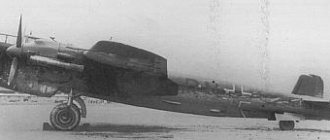
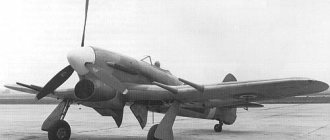
Messerschmitt BF-109 from the ceiling
Several photographs of the manufacturing process were borrowed from the article Foam Me-109e by the respected Yuri Alexandrov (Pumper) for which many thanks to him! At the time when I was building my Messer, there were no “brains” to photograph the whole process... But as it is... In the beginning there was a purchased Corsair F4U from hobbying Model of the Hobby King F4U Corsair airplane (Plug and Fly Kit) I learned on it, first to fly, then get on the “wheels”, which is probably why the beaten-down one still remains my favorite car! While learning to fly, and more specifically, take off and fall, I decided to make a model myself. At that time it seemed to me that it was much easier to do everything myself than to spend money... (later I realized that turning an apartment into a workshop for many days is not so pleasant, my wife grumbles, there is dust and dirt all around... unfortunately I don’t have a garage ...) I found the above-mentioned article, I really liked the plane! There is something bewitching and enchanting about it...
To begin with, I went shopping in search of ceiling tiles, wandered around, looked... I chose what seemed more or less suitable to me at that time, although I had no experience in this matter... I just stupidly looked at the eye for it to be thicker, about 3 mm and denser... In contrast from the author, who used a short ceiling for the fuselage and sculpted it in two parts, I found long plates from which one-piece spare parts for the fuselage were obtained.
First, I cut out the frames, then carefully glued two “sidewalls” of the fusel to them, then the top and bottom...
photo by Yuri Alexandrov
The wings (voluminous with ribs and a spar inside) from the ceiling seemed too flimsy to me, so it was decided to cut both consoles from a single piece of orange insulation material
with reinforcement in the form of an ordinary ruler glued into a ready-made structure.
The tail is also made from the ceiling, but in two layers. All hinged moving elements are held on with reinforced tape.
The aileron is reinforced with a wooden ruler at the end.
The entire structure of the plane was covered with fabric (something like chiffon, but cheaper, I stupidly went to the Fabric store and chose what my eye fell on...)
coated with two layers of aqualac
I have never regretted it, although I increased the weight a little, but strengthened the structure many times over!
photo by Yuri Alexandrov
To make the cabin, I took a thick film for the laminator, ran it through it, it became twice as strong, cut out a pattern, glued it, and then glued a stencil for the windows and spray painted it. After removing the stencil, I got windows 
I painted it with acrylic paints, in the absence of an airbrush, bluntly with a brush, all the signs were printed on photographic paper, cut out and covered with aqualac, in my opinion it turned out not bad!
At the moment the device is “charged”:
- 2200Mah battery
- Turnigy L3015A-1000 engine
- regulator TURNIGY Plush 40A
- propeller APC style propeller 10×5-E
The flight of this bird in the air looks amazing and very beautiful! Although we must honestly admit that the car is not so simple, it has all the makings of a prototype... it loves speed, is prone to falling onto the wing...
Overall I'm pleased
There is a short video, unfortunately of poor quality, but still...
all my articles:
INTRODUCTION
A brief general technical description of the Me-109-EZ aircraft is the first release in a series of technical descriptions of this aircraft and is intended primarily for workers in general groups. The description contains in a condensed form the necessary reference material for the designer, with the exception of the general layout of the aircraft. A detailed description of the individual components of the aircraft will be presented in the following issues of the technical description of the Me-109 EZ aircraft.The description uses reports from the research institute on testing the aircraft, reports from the 8th TsAGI laboratories; company descriptions and aircraft passports, drawings from the Bureau of New Technology and other materials. Lists of drawings available for the Me-109 EZ aircraft will be published as an appendix to the description of one or another aircraft unit.
GENERAL INFORMATION
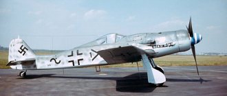
The Me-109 EZ aircraft (Fig. 1-6) is a modification of the all-metal Me-109 fighter.
The aircraft is equipped with a Daimler-Benz DV-601A engine with an in-flight variable pitch propeller. The aircraft's armament consists of four MG-17 machine guns, two of which are installed in the fuselage and two in the wing; the last two machine guns can be replaced by two 20-mm cannons - MGFF.
| Wing area | 16.4 m² |
| Wing load | 158.5 kg/m² |
| Rated motor power at an altitude of 3700 m at 2400 rpm | 1100 hp |
| Power Load | 2.36 kg/hp |
| Power per unit wing area | 67 hp/m² |
| Maximum ground speed | 500 km/h |
| Maximum speed at an altitude of 5000 m | 570 km/h |
| Ceiling (practical) | 11,000 m |
| Climb to 5000 m | 4.9 min |
| Turn radius at 6000 m | 320 m |
| Landing speed | 125 km/h |
| Take-off run (with a rise to a height of 20 m) | 420 m |
| Mileage (including landing from a height of 20 m) | 485 m |
| Flight duration at full throttle at an altitude of 6000 m | 1.1 hours |
| Flight duration on a throttled engine | 2.0 hour |
| Maximum permissible dive speed | ~ 750 km/h |
GLIDER
Fuselage (Fig. 7-11)
The shape of the fuselage, including the canopy, harmonizes well with the overall contours of the aircraft. The cross sections of the fuselage (Fig. 10) are well linked to the midsection of the engine and make it possible to achieve a good connection with the wing. The inverted type of two-row water-cooled engine and the low location of the wing determined the oval-shaped fuselage midsection, widened towards the bottom. For a low-wing aircraft, a midsection of this type predetermines a minimum of losses due to wing-fuselage interference. The fuselage midsection is 0.955 m².
From a structural and technological point of view, the fuselage can be divided into three compartments: the first compartment - from the fire bulkhead of the frame (I) to the frame (5) (Fig. 7.9); the second compartment - from the frame (5) to the frame (12) and the third compartment - from the frame (12) to the end of the fuselage. The first and second compartments do not have a sharp structural boundary between themselves; the third compartment is an independent unit (Fig. 8). The joint between the second and third fuselage compartments is made using bolts.
The first compartment of the fuselage is divided into two independent parts by an oblique solid sheet frame (3), the floor and the central part of the wing spar, which is also the bottom of the second frame. In the first, front, part of the compartment there is a machine gun mount with cartridge boxes, an instrument panel, an oil tank, a canopy and a pilot's cabin. Bolted to the frame (1), from below, are the attachment points for the landing gear, engine mount struts and the front wing assembly. On top of the same frame, fastening points for the upper beams of the motor mount and a machine gun pedestal are installed. The machine gun mount and the reverse side of the instrument panel are covered with a removable hood, which is a continuation of the hood of the propeller-engine group. By removing the hood, you can gain access not only to the weapon, but also to the rear of the instrument panel, which makes it easier to install and remove instruments. In the second half of the right compartment, behind the frame (3), there is a gas tank and a pilot’s trunk, the hatch of which opens from the cockpit. The fuel tank hatch opens from the bottom of the fuselage.
The second compartment of the fuselage houses oxygen cylinders, radio equipment and a battery. There is a pipe running through the fuselage near the frame (II), and by passing a lifting rod through this pipe, you can lift the tail of the aircraft. When transporting an aircraft, a rod is used to secure the fuselage to the railway platform. A crutch, the front keel assembly, a lift and stabilizer struts are attached to the frame (12) of the compartment (Fig. 8). The second fin assembly and the second stabilizer assembly are attached to the rear, third compartment.
The second compartment of the fuselage houses oxygen cylinders, radio equipment and a battery. There is a pipe running through the fuselage near the frame (II), and by passing a lifting rod through this pipe, you can lift the tail of the aircraft. When transporting an aircraft, a rod is used to secure the fuselage to a railway platform. A crutch, the front keel assembly, a lift and stabilizer struts are attached to the frame (12) of the compartment (Fig. 8). The second fin assembly and the second stabilizer assembly are attached to the rear, third compartment.
The transverse set of the fuselage consists of thirteen frames, seven of which are formed by flanging the skin sheets. The longitudinal set consists of six short spars made of pressed duralumin corners, and twelve stringers made of drawn profiles. The four upper spars have flanges of 4 mm thickness, and the two lower spars have flanges of 6 mm thickness. The casing and its cutting are shown in Fig. eleven.
In fig. 12 shows the upper attachment point of the motor mount to the fuselage, and in Fig. 13 shows the installation of the landing gear assembly on the fuselage. This unit is one of the most important on an airplane, since it performs several functions simultaneously: the following are attached to it: I) the landing gear and the landing gear lock in the extended state, 2) the lower strut of the engine mount and 3) the front wing assembly. Both the attachment point for the upper beams with motors and the chassis assembly are cast steel.
A diagram of the reinforcement of the landing gear components from the side, as well as a diagram of the transmission of forces to the central section of the wing spar are given in Fig. 14, which shows a section of the fuselage (along A-A, Fig. 9, fuselage frame, starboard side).
The middle part of the wing spar, connected to the second frame, consists of two steel shelves (6) and (II) (Fig. 15), interconnected by a vertical wall (13) and for rigidity by diaphragms (12) and (14). The shelves (6) and (II) end at the joints with the wing. A Hooke's ball is inserted into the upper assembly to ensure easy mating with the wing assembly.
The canopy (Figs. 16 and 17) consists of three parts: a fixed front one - frontal, a middle one - folding, which serves to enter the cabin, and a rear one - to improve visibility to the rear. An adjustable cockpit ventilation valve is installed in the front part of the canopy. There are also two handles attached here, by grabbing which the pilot can pull himself up and stand in the cockpit.
During normal operation, the rear part of the canopy is rigidly connected to the fuselage, and the middle part can be folded to the starboard side and held in this position by a cable. In the event of an accident, the pilot uses the handle (2)
can reset the middle and rear parts of the canopy.
The emergency mechanism of the lantern consists of a handle (1) (Fig. 17), rods (4) and (14), two units (II) and (III), two springs (19) enclosed in pipes (8), and a hook ( II) with pocket (10). The installation of pipes (8) is also visible in figure (16), where they are indicated by position (1).
When dropping the lantern, the handle (1), through the rod (4), with the help of the slider (57), moves the rod (14). The displaced rod (14) in turn puts the rods (58) and (62) in such a position that the bolts (59) of the lantern under the action of the spring (61) (C-C section) come out of contact with the rods (50) and ( 62). As a result, the springs (19), compressed between the stops (7) on the fuselage and the stops (9) on the canopy, throw the rear part of the canopy into the air, and at the same time the middle part of the canopy connected to it by a cable. According to British information, on some aircraft the pilot's head is protected from behind by 8 mm armor attached to the rear of the canopy.
Technological features of the fuselage
Based on the study of available materials, a number of conclusions can be drawn about the features of aircraft fuselage technology.
1. The second fuselage compartment as can be seen from Fig. 9 and 11, was made based on simplified production methods. The compartment consists of two symmetrical “shell” halves. The joint of both halves is made using longitudinal bent profiles of 1.5 mm thickness. These profiles also serve as stringers. Each half of the shell is formed by seven panels, and the panels (5-6), (7-8), (9-10), (11-12) are stamped (each from one whole sheet) in such a way that their transverse sides form half-frames. Each shell is riveted and assembled separately and completely independently. The connection of both shells is made using connecting stringers, connecting both shells into one whole, and butting plates connecting the halves of the frames (Fig. 8, node A). To install the longitudinal set in the appropriate places, slots with flanges are made in the frames (Fig. 8, node B).
2. Pipeline connectors and aircraft control joints are located on the fire bulkhead and fuselage sides between frames (1) and (4). This makes it possible, firstly, to independently assemble the wing, fuselage and propeller group, and secondly, to assemble and disassemble the aircraft in the shortest possible time.
3. A very large number of hatches and hatches are installed on the fuselage, facilitating operation and installation, for example:
The gasoline filler hatch with a drawn yellow triangle with the number 87 indicates that the hatch covers the gasoline filler neck and that the gasoline being filled must have an octane rating of 87.
Oil filler flap with “Rotring” inscription. indicates that this hatch covers the oil filler neck and that only the specified brand of oil should be filled.
The hatch for the gas tank, through which the tank is inserted into the fuselage from below, is closed with a large hatch cover on anchor nuts. The sides of the hatch are reinforced with 4 mm bent profiles. The hatch on the left side of the fuselage provides access to the radio installation and battery. The hatch in the fuselage cockpit, behind the head of the pilot's seat, serves to access the trunk. An easily removable weapon hood provides access to the weapon and to the back of the instrument panel.
4. The symmetry axes of the fuselage and the aircraft are fixed on the top of the fuselage and on the sides by installing rivets with a semicircular head. The rivet heads are painted red. The position of the axes on the rivets is marked with a mark.
Wing
The Me-109 aircraft is cantilever, trapezoidal in shape with slightly rounded ends.
The angle of installation of the wing in relation to the construction plane of the aircraft is 1° 42′. The transverse angle V related to the lower chord of the spar is 7°10′. The wing has no twist.
Structurally, the wing consists of two detachable consoles that are connected to the fuselage at three points. Each console has slotted ailerons, slotted flaps and automatic pre-flaps operating at speeds below 180 km/h. Each console is equipped with a radiator and an MG-17 machine gun or MG-FF cannon with ammunition.
The wing is all-metal, single-spar. The spar and skin absorb bending forces. Torsional forces are perceived by the skin (the working sock and the caisson part of the wing). The wing is attached to the fuselage at three points. Wing spar
beam type with massive duralumin T-section shelves and a duralumin wall, which is supported by reinforcing elements. Wing ribs are partly beam, partly truss type
To retract the landing gear in flight, a cutout is made in the lower surface of the wing in the shape of a landing gear with a wheel. The cutout for the stand is sewn from the inside with 1.5 mm duralumin, thus forming a rigid tray. The wheel cutout is separated from the inner fender structure by a canvas cover with zippers.
The wing joints and their location on the side rib are indicated in figures 20 - 22. As can be seen from these figures and figs. 15, the center section spar lower chord assembly consists of a fork, and the console spar lower chord assembly consists of an ear with a ball insert. The center section spar upper flange assembly is an ear with a ball bearing, and the console spar upper flange assembly consists of a fork. The axes of the bolts of the upper and lower units are mutually perpendicular. The advantages of this design for interchangeability in mass production are quite obvious. The distortion of the ears and forks is leveled with the help of ball inserts.
The front assembly (Figs. 20 and 22, view along arrow C) is a flange with an ear and a ball bearing. The flange is mounted on the wing with four bolts on a light alloy part. Both on this part and on the flange of the butt joint, triangular-shaped slots in cross-section are selected, which makes it possible to adjust the installation size of the ear along the base between the butt joints. A system of joint assemblies made according to the specified type fully ensures complete interchangeability of wings and fuselages.
The front unit is mounted on the cantilever part of the wing near the landing gear tray. The latter, when transferring torsion from the console to the fuselage, obviously plays the role of an additional spar.
Wing mechanization. In order to increase the wing Su and ensure stable operation of the wing at high angles of attack, slats and slotted flaps are installed on the wing.
The slats open automatically at speeds below 180 km/h. The kinematic diagram of the slats mechanism is shown in
Aileron
The aileron chord is maintained over the entire span at the rate of 25% of the length of the chord of the wing of the corresponding section. The ailerons are aerodynamically and 100% weight compensated. The aileron frame is made of duralumin, covered with fabric, and has a compensation plate.
Tail
Stabilizer - strut type, detachable. Its characteristic feature is its simplicity of production. Each half of the stabilizer is assembled from two independent panels - upper and lower, which are then riveted together, as indicated in
The stabilizer nose is screwed in after assembly. Anchor-type nuts are riveted into the stabilizer structure during general assembly. Stabilizer installation angle + 3°; in flight, the angle of attack can be changed up to -8°.
The keel of the aircraft is removable, the profile is asymmetrical; The casing and frame are made of duralumin. The design of the keel, from a technological point of view, is designed in the same way as the stabilizer.
The steering wheel and elevator have a duralumin frame and fabric covering. The suspension of the steering wheel and each elevator is made at three points. Aerodynamic compensation of the rudders is horn. The handlebars, according to the company, are 100% weight compensated.
There are no tail trimmers. The elevator has a compensation plate with an area of 0.93% of the rudder area.
Control
The rudder control is soft. Instead of cables, wire was used, laid in textolite guides installed on the frames.
The elevator control is semi-rigid: from the control stick to the frame (5), forces are transmitted through tubular rods and rockers; further, to the rocker in front of the elevator, the transmission is carried out in the form of duplicated wire wiring in textolite guides; From the tail rocker to the elevator lever, the transmission is a rigid rod. The elevator control circuit includes a weight balancer (Fig. 21, item 1)
Aileron and flap control is tight. Aileron deflection up – 26°40′, down – 13°20′. Flap deflection -42°. When the flaps are deflected down, the ailerons also drop by 12°30′. As can be seen from Fig. 26, the flap and stabilizer control wheels are located side by side, and if you simultaneously grab both steering wheels with your hand, you can lower the flaps and lower the stabilizer.
The mechanism by which flaps and ailerons work together is quite simple. A pipe (2) is installed across the fuselage (Fig. 26), with a gear wheel (3), which receives rotation from the steering wheel through a Gall chain (4). On both sides the pipe ends with couplings of different rotations. Worms are screwed into the couplings, at the ends of which rockers (7) are hinged, to which three rods are attached. The rod (8), connected to the rocker (9), which receives rotation from the handle (10), is attached from above. In the middle, to the rocker (7), a rod (6) is attached, going to the ailerons. A rod (5) leading to the flaps is attached to the rocker (7) from below. When the flaps are raised, deflecting the handle to the right and left sets the rocker (9) in motion, which, by means of a rod (8), deflects the rocker (7), turning it around the lower hinge, as a result of which the rod (6) transmits the movement to deflect the aileron. When the flap steering wheel rotates, the pipe (2), turning around its axis, pushes out the worms screwed into the couplings and deflects the rockers (7), turning them around the upper hinge, as a result of which the rods (5) and (6) move in the same direction the same side, deflecting both the flaps and ailerons at the same time. As can be seen from the diagram, with the flaps deflected, the ailerons can work normally, only the initial position angle of the ailerons themselves will not be 0°, but 12°30′.
The stabilizer control consists of a wheel, a Hall chain enclosed in pipes in a certain section, cables and a lift-lift connected at one end to the fuselage and the other to the front spar-spout of the stabilizer,
CHASSIS
The aircraft's landing gear is retractable, single-post, cantilever type. The stand is attached to the fuselage, and cleaning is carried out in the direction from the fuselage to the end of the wing. Comparative data with other German aircraft is given at
Data on the Me-109 chassis is given below.
| Chassis data: | |
| 1. Static load in three-point position: | |
| On chassis wheels | 2333 kg; |
| On a crutch wheel | 275 kg |
| Parking angle | 14° |
| 2. Track width | 2000 mm |
| 3. Chassis wheel | 650Х150 mm |
| Pneumatic pressure | 3.2-4.0 at |
| 4. Tail wheel | 290Х110 mm |
| Pneumatic pressure | 2.54 at |
Chassis shock absorber
oil-pneumatic, with main braking in reverse. Its data: mixture volume - 1.1 l; charging pressure - 25 at; stroke - 238 mm; weight - 21 kg.
The spring-oil shock absorber of the crutch installation has a stroke of 117 mm and a weight of -8.4 kg.
A bracket (6) is rigidly fixed to the upper part of the shock-absorbing strut
with a hole for the axle (7) connecting the stand to the unit (1). The rotation of the stand during cleaning occurs around this axis.
The landing gear can be extended in two ways: normal - using hydraulics and emergency - under the influence of its own weight. The chassis hydraulic system diagram is shown in
The chassis is equipped with mechanical locks for the extended and retracted positions of the landing gear. The released position lock is shown in The rack is locked by a cam (3). which is wedged between the bracket (6) rotating together with the stand and the stop (4) rigidly fixed to the unit (1). The cam (3) can rotate around an axis (5) mounted on the bracket (6). The lock is opened by rotating the cam around this axis under the action of the power cylinder rod, hinged to the cam. After turning the cam and opening the lock, further extension of the rod raises the shock absorber strut. A spring in the cylinder (2) helps press the cam into the closed position.
The chassis suspension clamp in the retracted position consists of a hook (5) with a spring (1) that engages with the ear (6) on the strut. It is opened before release by the power cylinder (2), and in case of emergency release - by tensioning the cable (3).
The pressure in the hydraulic system is created by a hydraulic pump installed on the engine. The retraction and extension of the landing gear is controlled by a special switch installed on the dashboard. There is a mechanical chassis position indicator. The volume of the hydraulic system reservoir is 2.52 l. It is installed near the engine supercharger.
The shock-absorbing landing gear strut and the crutch mounting strut have been manufactured (BNT technical description No. 1). The results of testing the rack at the research institute are shown on
<< | >>