Medieval Siege Cannons
Black gunpowder - a mixture of sulfur, coal and potassium nitrate - was invented in China at the dawn of our era, but it began to be seriously used to push a projectile out of a gun barrel in Europe, where “firearm ideas” came through Arab countries.
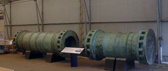
The first cannons were used already in the 13th century to destroy fortress walls. The siege weapons were huge and clumsy, and did not have a carriage with wheels. The multi-ton bronze barrel was placed on log supports with the muzzle facing the fortress, and to prevent it from tipping over from the recoil of a shot, the flat wall of the charging chamber was supported from behind by wooden stakes and masonry walls. Then it was loaded for a long time: gunpowder and felt wads were put into the breech of the bombard barrel, and at the end a stone or metal core was rolled in. Then the gunpowder was ignited through a special ignition hole and - bang! The projectile flew to the target or... did not fly. It often happened that the cannon itself exploded, killing its servants. It depends on your luck.
GENERAL INFORMATION
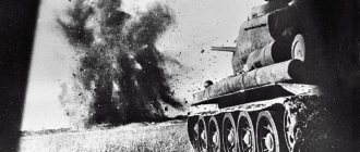
The T-34-85 tank is equipped with an 85-mm tank gun model 1944 (When studying the design of the gun, use the manual “Service Manual for the 85-mm tank gun model 41”, Voenizdat, 1946) and two tank machine gun DTM 2 7.62 mm (When studying the design of the DTM machine gun, use the manual “Guide to the DTM machine gun”, Voenizdat 1946).
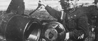
The cannon and one machine gun are installed in tandem in the tank turret. Another machine gun is installed in the upper frontal plate of the tank hull. The cannon, coaxial with a machine gun, is installed in the tank turret (Fig. 47) on axles whose axis is horizontal. Rotation of the twin mounting on axles using a lifting mechanism ensures that the cannon and machine gun are given elevation and descent angles. The machine gun, coaxial with the cannon, is installed in the socket of the machine gun mount and secured in it by turning the clamping ring.
The machine gun mount is bolted to a bracket mounted on the gun cradle. The frontal machine gun is installed in a ball mount (Fig. 48), which is mounted in the ball socket of the tide of the armored cap, welded to the edges of the oval hole in the upper frontal plate of the tank hull. The machine gun is installed in the ball socket and secured by turning the handle of the clamping ring. Using a ball mount stopper, the machine gun can be secured in the desired position.
Leather guns
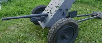
The first cannons were suitable for siege and defense of fortresses, but were too heavy for use in field battles, although many military leaders understood the need for light field artillery. In those days, they fought in close formation: the warring armies lined up full-length regiments opposite each other at a distance of only a few hundred meters. It’s easy to imagine what would happen if a cannon fired at such a bunch of targets and from such a distance almost point-blank, not with a cannonball, but with a whole sheaf of bullets - buckshot. It will immediately mow down several rows of enemy soldiers! The French army fighting in Italy in 1494 first tried to drag small cannons with teams of pack animals and use them in field battles, which became a tactical discovery for the 15th century. French 3-pound cannons (it was not the cannon that weighed 1.36 kg, but its cannonballs - it was their weight that then determined the caliber of the guns, and not inches or millimeters, as today) weighed almost half a ton, they were transported by teams of four horses, so the maneuverability of such guns was very conditional. Accompanying your advancing troops did not work out very well.
In the Middle Ages, cannons were either cast from bronze or forge-welded from iron strips held together with hoops. Both methods did not allow achieving high strength: when casting, cavities were obtained in the walls of the barrel, and welded barrels easily separated at the seams under the pressure of powder gases. It was necessary to increase their strength at the expense of thickness and, consequently, increase in weight.
HOW IS THE WEAPON CONSTRUCTED?
HOW IS THE WEAPON CONSTRUCTED?
An artillery gun is a powerful heat engine, original in the conditions and nature of its action. The operating principle of the gun is based on the use of the energy of powder gases. During a shot, the barrel and projectile are exposed to powder gases, the pressure of which reaches 3000-4000 kgf/cm, and the temperature - 3000 °C. The power of a medium-caliber gun is 400–900 thousand hp, and that of a large-caliber gun is 9–12 million hp. For comparison, let us recall that the power of the domestic 122-mm howitzer of the 1938 model was about 130 thousand kW (1 kW = 1.36 hp), and the power of the first Soviet regional hydroelectric power station built on the Volkhov River was 66 thousand. kW. The efficiency of artillery guns is considered very high - up to 35 percent. This is equivalent to the efficiency of internal combustion engines and significantly greater than the efficiency of steam engines.
Let's look at the two most typical concepts - howitzers and mortars. In any modern weapon, the main structural elements of these schemes vary to one degree or another.
The Soviet 122-mm howitzer D-30 with all-round fire consists of two main parts - a barrel and a carriage.
The barrel is the basis of the weapon. It gives the projectile a given direction of flight, the necessary initial speed and rotational motion. The barrel includes a monoblock pipe, a breech, two clips, a muzzle brake and a pivot beam.
The barrel bore has a chamber and a rifled part. The chamber is smooth. It contains a cartridge case with a powder charge and the rear part of the projectile. There are 36 helical grooves in the rifled part of the barrel. They go from left to top to right when looking into the bore from the breech side. Therefore, the projectile rotates clockwise.
The breech houses the bolt. The clips are used to attach recoil devices.
At the muzzle of the barrel there is a muzzle brake designed to absorb 50 percent of the recoil energy. The muzzle brake has an axial hole for projectile ejection and six side windows for the exit of powder gases. When a projectile flies out of the barrel, the gases following it hit the walls of the windows with force and sharply push the brake forward along with the barrel. In this case, a reactive force also arises, acting in the direction opposite to the rollback. Thus, the muzzle brake reduces the effect of the shot on the gun carriage by reducing the energy of the recoil parts. If there is a muzzle brake, recoil devices absorb only the remaining half of the recoil energy.
Therefore, they are compact, small in size and weight, and not burdensome for the weapon as a whole.
A pivot beam is bolted to the bottom of the muzzle brake. It is needed to connect the howitzer to the tractor during transportation. This is one of the distinctive design features of this howitzer.
Readers have seen many artillery systems more than once, and they are accustomed to the fact that the tractor tows the gun by the trunk part of the frame, as they say, with the barrel backwards. In this case, the picture is different: the tractor tows the howitzer by the muzzle of the barrel. A similar method, as is known, was used when towing domestic 160-mm and 240-mm mortars.
The howitzer uses a vertical wedge bolt with a wedge that lowers when opened and with semi-automatic mechanical type.
The wedge bolt consists of several mechanisms: locking (locks the barrel bore when fired), impact (fires a shot), ejection (throws out the cartridge case after the shot and holds the wedge in the open position), re-cocking (cocks the impact mechanism in case of misfires without opening the bolt), safety (does not allow you to fire a shot when the bolt is not completely closed), a holding mechanism (makes it easier to load the gun when firing at high elevation angles).
The need for the latter shutter mechanism is explained by the very significant elevation angles of the barrel (up to 70 degrees), and the essence of its operation is visible from the process of loading the gun. The howitzer is loaded like this: the projectile is placed in the barrel chamber behind the retainer; With its bottom, the projectile rests against the holder and cannot fall out of the barrel. After this, the projectile is sent into the barrel with a special hammer, and only then a cartridge case with a powder charge is inserted.
The main part of the bolt is a massive wedge in the form of a tetrahedral prism with a recess (tray) on top to guide the projectile and cartridge case during loading. The front surface of the wedge is perpendicular to the axis of the bore, and the rear (support) edge forms an angle of several degrees with the front. The wedge seems to taper towards one end. This design solution ensures reliable locking of the barrel bore.
The ease of opening and closing the wedge gate allows the use of automation elements here, which creates favorable conditions for increasing the rate of fire and facilitates the work of the combat crew.
The howitzer uses a semi-automatic copy type. It serves to automatically open and close the shutter and accordingly consists of an opening and closing mechanism. When the barrel rolls back after firing, the semi-automatic opening mechanism ensures that the bolt opens and the spent cartridge is ejected without human intervention. The semi-automatic closing mechanism automatically closes the bolt after loading. It happens like this. When loading, the cartridge case with its flange strikes the ejector grips, which release the wedge. Under the action of the closing spring, the wedge rapidly rises up and securely locks the bore. When the barrel rolls back, the cam of the opening lever slips past the stationary copier back. When the barrel rolls, the cam runs into the copier and turns the axis of the cranks, which open the bolt. Simultaneously with the opening of the shutter, the closing spring is compressed. In this way, energy is accumulated to close the bolt after loading.
The howitzer carriage includes: a cradle, recoil devices, upper and lower machines, aiming mechanisms, a balancing mechanism, frames, chassis, shield.
The cradle is designed to guide the barrel during recoil and retraction; it also contains anti-recoil devices.
Anti-recoil devices serve to smoothly decelerate the recoil parts of the howitzer when fired, return (roll) them to their original position and reliably hold the barrel in the extreme forward position before firing at any elevation angle.
Recoil devices consist of a hydraulic recoil brake and a hydropneumatic knurler. Without going into details of the complex physical picture of the operation of recoil devices during a shot, we note that the recoil brake converts mechanical recoil energy into thermal energy (due to compression resistance and friction that occurs when liquid splashes through small holes). The rest of the recoil force is spent on compressing the air in the knurling cylinders.
When all the recoil force is absorbed and the barrel stops in the rear position, the compressed air of the knurl will begin to expand and roll the barrel.
The upper machine is the base of the swinging part of the howitzer. The cradle, lifting, rotating and balancing mechanisms, shield and chassis are placed and secured on it. Note that in artillery guns of classical designs, the chassis was always part of the lower carriage of the carriage. In the howitzer under consideration, it turned out to be rational to take an unusual design decision - to mount the wheels on the upper machine.
The upper machine rests on the lower machine and rotates on it in a horizontal plane.
The lifting mechanism of a sector-type howitzer. When the flywheel rotates, the shaft with gear engages with the cradle sector and causes the cradle, together with the barrel, to rotate in a vertical plane.
The rotating mechanism serves to rotate the rotating part of the howitzer 360 degrees.
To balance the swinging part of the gun relative to the axle axis and relieve the lifting mechanism, the howitzer uses a push-type pneumatic balancing mechanism. It consists of outer and inner cylinders, sealing and valve devices. The compressed air between the two cylinders props up the cradle and thereby reduces the effect of the weight of the muzzle on the lifting mechanism.
The energy from the balancing mechanism is also used in the wheel lifting mechanism. It raises the wheels when the howitzer is brought into firing position.
The shield protects the gun crew from the impact of the shock wave when fired, fragments and bullets.
The howitzer's chassis consists of a travel axle, wheels and torsion bar suspension. It is mounted in the nozzles of the upper machine. When the wheels hit an obstacle, the torsion rollers twist and soften the impact. Since steel has elasticity, when the wheels leave an obstacle, the torsion rollers unwind. The torsion of the rollers occurs within the limits of elastic deformation, so they act like springs.
The lower machine houses the rotating part of the howitzer. One fixed frame is welded to the nozzle of the lower machine, and the other two are hinged to it. In the combat position, the movable frames are moved apart at an angle of 120 degrees relative to the fixed frame and in this state are fixed with stoppers. In the stowed position, the movable frames are brought together to a stationary one and secured, and the stationary frame is connected to the barrel at its muzzle.
A jack is placed in the central hole of the lower machine. It is designed to raise and lower the howitzer when transferring it from the traveling position to the combat position and back. The jack has a rotating tray, screws, gears, and two folding handles. To roll the howitzer over short distances using crew forces, a special removable roller is used.
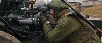
The howitzer is aimed at the target using sighting devices: a mechanical sight with a gun panorama for firing from closed positions and an optical sight for direct fire. Both sights are located on the cradle bracket on the left side. At night and in poor visibility, they are illuminated with a special device.
The general trend in the development of artillery weapons is the constant improvement of the ballistic, design and operational characteristics of guns. For example, let's take three specific samples of domestic 122-mm howitzers.
The first of them, a 122-mm howitzer of the 1910/1930 model, had a single-beam carriage without sliding frames. This already predetermined a very small angle of horizontal fire. The 122-mm howitzer of the 1938 model had a very successful carriage with two sliding frames - the horizontal fire of the gun immediately increased 10 times and reached 50 degrees. And the three-frame carriage of the 122-mm howitzer provides all-round fire. This example clearly shows the progressiveness of the Soviet artillery design school.
The design of a classic muzzle-loading mortar is very simple. The main parts of the mortar: a barrel with a breech, a two-legged carriage, a base plate, a sight and a safety device against double loading.
The barrel, as a rule, is a smooth-walled pipe, closed at the rear by a breech.
If in modern guns the highest pressure of powder gases in the barrels reaches 4000 kgf/cm2, then in mortars it does not exceed 1000 kgf/cm2, that is, four times less. Therefore, mortar barrels are made thin-walled and, therefore, lightweight.
The breech screws onto the back of the barrel tube. At the bottom of the breech there is a firing pin, onto which the mine is impaled with its primer when it is lowered into the barrel. From below, the breech ends in a ball heel. It serves to connect the barrel to the base plate. A hole is made in the ball heel through which a crowbar is inserted to make it easier to screw the breech onto the barrel pipe and screw it off the pipe.
A rigid firing pin screwed into the bottom of the breech ensures a simple design and a high rate of fire. In 107-120 mm mortars, a cocked percussion mechanism is more often used. It has two positions: rigid and cocked. In the second case, the firing pin is recessed before the trigger lever is retracted, so the possibility of spontaneous breaking of the mine primer during loading is eliminated. Firing with a cocked striker is carried out when, after loading, it is necessary to check the aiming, and then withdraw the combat crew from the mortar to cover.
The two-legged carriage supports the barrel and gives it vertical and horizontal guidance angles. It contains lifting, rotating, leveling mechanisms and a sight. The two-legged carriage is connected to the trunk using a clip and a basting. All mortar aiming mechanisms are screw type.
The leveling mechanism is designed for precise leveling of the mortar in cases where the sight is rigidly mounted on a two-legged carriage. There is no need for precise leveling if a swinging mortar sight is used.
When a mortar is fired, the recoil force absorbed by the base plate is transferred to the ground. Due to the elasticity of the soil and the slab, the trunk moves along the axis by a certain amount and then returns to its original place. To prevent damage to the mortar mechanisms during a sharp rollback of the barrel, the two-legged carriage is attached to the barrel using spring shock absorbers.
The base plate serves as support for the barrel. It consists of a main sheet to which stiffeners are welded from below. Distributing the recoil force over a large area helps reduce ground pressure.
In mortar designs, optical and mechanical sights are most common. Each mortar sight has a protractor and a sight scale. The goniometer is designed to measure horizontal angles, and the scope itself is designed to measure vertical angles.
The double-loading fuse prevents the mortar from being loaded with a second mine when there is already one live mine in its barrel. It is attached to the muzzle of the barrel. All domestic muzzle-loading mortars are equipped with reliable and automatically operating fuses against double loading.
They work flawlessly when firing mines of any type, on all charges provided for a given mortar, at any elevation and horizontal guidance angles, at different rates of fire and from firing positions on any ground.
The design of large-caliber mortars is much more complicated. But in principle they have the same basic design elements: a smooth-walled barrel, a carriage with wheels, a base plate, and a sight.
Large-caliber mortars are loaded from the treasury. The long barrel and heavy mine do not allow for muzzle loading.
To ensure that the barrel opens during loading and locks at the moment of firing, the barrel of a large-caliber mortar is divided into a swinging part and a breech. The swinging part is a pipe that is open at both ends. It is held in the loading position by a locking mechanism. The breech in the closed position is the bottom of the barrel. It securely locks the barrel when fired and transfers the recoil force to the plate. In addition, the breech serves as the base on which the barrel tube is rocked and locked at loading angles, as well as the barrel is connected to the carriage by means of spring shock absorbers.
The carriage is the base of a large-caliber mortar in combat and traveling positions. The carriage contains lifting, turning and balancing mechanisms, a chassis with a suspension mechanism and a sight. The mortar is towed by a vehicle, the coupling device of which is connected to the muzzle of the barrel using a muzzle, which is put on the barrel in the stowed position.
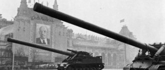
A self-propelled gun consists of weapons, a body, a power plant, a transmission, a chassis, electrical and special equipment, communications and surveillance equipment. All these parts are usually located in four sections of the hull: combat, engine, transmission and vehicle control.
Armaments include artillery pieces, aiming and surveillance equipment, small arms and transportable ammunition.
The power plant includes an engine with power supply, lubrication, cooling and air purification systems. The transmission includes a main clutch, a gearbox, side clutches or a planetary rotation mechanism, and a final drive (gearbox).
The chassis consists of tracks, drive wheels (sprockets), guide wheels (sloths) with tensioning devices, support and support rollers, suspensions (springs).
Electrical equipment includes batteries, a generator with a relay regulator, a lighting network and individual electricity consumers.
Communication means are divided into internal and external communication. Internal - for communication between the commander of a self-propelled gun and crew members. It can be telephone, laryngophone and light signal. External communication is carried out by a transceiver radio station with a range of 20–25 kilometers.
Surveillance equipment is intended for the vehicle commander, driver and gunner. These are mechanical and optical instruments.
The fighting compartment in self-propelled guns is located in the front, middle or rear of the vehicle. When assembling the elements of a combat vehicle, they proceed from the most efficient use of weapons, to better ensure the indestructibility of all units, and to achieve good mobility and maneuverability of the weapon. The dimensions of the fighting compartment are determined by the caliber and type of weapon, the layout of the weapon, the sweep radius of the fence of the swinging part of the gun, the composition of the crew and the amount of ammunition carried.
The armament of self-propelled guns differs in design from towed artillery. Significant features of self-propelled guns: armoring of the swinging part, special arrangement of recoil devices, use of fencing, sleeve deflectors, sleeve catchers, sleeve outlets, rammers and mechanisms for feeding the shot set to the loading line, purging and ventilation of the fighting compartment.
Self-propelled guns are usually equipped with two or three bolt release mechanisms - electric ignition, electromagnetic and mechanical. The latter is a spare. The electric ignition trigger mechanism compares favorably with others due to its very short shot delay time, small dimensions and simplicity of design.
When developing self-propelled guns, special attention is paid to the placement and stowage of ammunition. The transported ammunition must be compact and conveniently located in the fighting compartment. This helps to increase the rate of fire.
Multiple launch rocket artillery launchers are significantly different in design from the usual designs of guns, howitzers or mortars, although they have a number of common components and assemblies. The launchers can be placed on the chassis of off-road vehicles, armored personnel carriers, two-wheeled carriages, or are lightweight launchers installed on the ground.
Modern self-propelled multiple launch rocket artillery launchers are usually called combat vehicles. They consist of artillery and chassis.
The artillery unit includes a package of a certain number of barrels, a rotating frame, a stand, lifting, rotating and balancing mechanisms, electrical equipment, and sighting devices.
The chassis is the chassis of an all-terrain army vehicle. All the main components and assemblies of the artillery unit are mounted on the chassis side members.
The barrels are designed to guide the flight of rockets; they are arranged in several rows parallel to each other. The barrel package is fixed in a rotating frame and can move in a vertical plane, that is, it is a swinging part of the launcher.
The rotating frame is used to move the package of barrels in a horizontal plane. It contains lifting, rotating and balancing mechanisms, and sighting devices. The rotating frame is mounted on a stand and is a rotating part of the launcher.
The stand serves as a support for the rotating part. It is mounted on a subframe, which is firmly connected to the chassis side members.
The aiming mechanisms are practically no different from the corresponding mechanisms of artillery guns.
Electrical equipment is designed to ignite powder charges of rockets. It consists of batteries, a firing device, a remote coil and cables. From the batteries, current is supplied to the firing device installed in the vehicle's cabin, and from it through cables to the contacts of the barrels. From here the current flows to the shell squibs. The remote coil is used when firing from cover located tens of meters from the combat vehicle.
Special equipment for the vehicle's chassis consists of cabin protection, gas tanks, and rubber wheel tires. Cabin protection (easily removable metal shields) protects the cabin and the crew in it from the dangerous effects of gas jets when firing.
Jacks ensure the stability of the combat vehicle when firing and unload the springs of the rear axles of the chassis. Using jacks, the machine is leveled on uneven terrain.
The designs of the launching devices include locking and locking devices for fastening rockets in the barrels and creating the necessary boost force, allowing the projectiles to leave the barrels at a certain speed and reducing their dispersion along the trajectory.
Any weapons, including artillery, must always be kept in a state of combat readiness.
When working with guns, howitzers, mortars, and rocket systems, artillerymen need to know and strictly follow the rules for operating weapons.
To do this, first of all, you should study and become familiar with modern weapons in order to master them perfectly.
