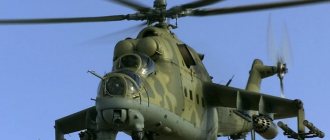
Transport and combat helicopter Mil Mi-24 - design and design. Part 1
In 1962, the American military group in South Vietnam began to use the new Bell UH-1 “Hugh” helicopter, which was smaller and more maneuverable than older types, which made it possible to use it not only for maneuvering troops on the battlefield, but also for destroying manpower. enemy strongholds, artillery and armored vehicles. And in 1965, the AH-1G Hucobra fire support helicopter was created on its basis.
The USSR Ministry of Defense demanded that the aviation industry make a multi-purpose helicopter, but the experienced design bureaus of N.I. Kamova and M.L. Mil were unable to “meet” the strict weight and size restrictions - the Ka-25F was rejected, and the military agreed to accept the Mi-24 in the form in which it was - much larger than desired.
Thanks to this decision, the Soviet Army received a helicopter that still remains unsurpassed in its combination of speed, maneuverability, capacity and weapon power.
In this part of the article we will look at the development of the helicopter project, as well as the design of its power plant and airframe.
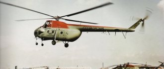
On September 19, 2019, the Mi-24 celebrates its half-century anniversary. It’s amazing how long this rotorcraft remains one of the best army aviation helicopters in the world. Photo by S.G. Frost
Preliminary Projects
Transport and combat helicopter - preliminary project . The development of the appearance of a transport-combat helicopter capable of transporting soldiers with personal weapons and independently fighting enemy manpower and equipment began at OKB-329 GKAT under the general and direct leadership of Mikhail Leontyevich Mil began in the second half of the 1950s.
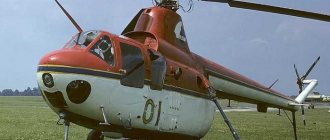
As a result, in 1958, two types of such helicopters were created, each of which was a modernization of a serial product and existed in several versions - the light Mi-1MU and the medium Mi-4AV.
The Mi-1MU helicopter was quite maneuverable, thanks to its small size it was convenient for use on the battlefield and relatively difficult to hit. But the low power of the power plant did not allow it to achieve high vertical and horizontal speeds or have sufficient capacity and armament.
Although the Mi-4AV helicopter was used for some time in the army aviation units of the USSR Air Force, the Customer was not satisfied with its performance characteristics, first of all, speed and maneuverability, as well as survivability - the Mi-4AV with its large size turned out to be too vulnerable to ZSU fire.
In addition, the Mi-1 and Mi-4 helicopters were considered obsolete by that time and the Customer demanded that the design of the new helicopter be brought closer to the V-8 (Mi-8). The USSR Ministry of Defense became interested in the proposal to create a new transport and combat helicopter, but at that time the TTT had not been formed, the draft Resolution of the USSR Council of Ministers for the design and construction of prototypes had not been prepared, and the work was carried out by OKB-239 on its own initiative from its own funds. At that time, the USSR Ministry of Defense did not pay enough attention to equipping the USSR Armed Forces with helicopters, focusing on missile weapons of both the Ground Forces and the Air Force.
However, the sharp increase in the use of helicopters by the Americans and their allies in the war in Southeast Asia (and the number deployed there from 1964 to 1974 increased from 400 to 4000) changed the position of the leadership of the USSR Defense Ministry. Particularly notable were the multi-role Bell UH-1 Huey helicopters and the specialized Bell AH-1G Hueycobra fire support helicopters. A study of the experience of their use confirmed their high combat effectiveness, which made it possible to achieve budgetary financing of the work and speed it up.
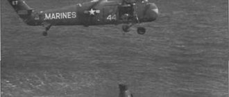
The combat use by American aviation of transport and combat helicopters Bell UH-1 "Hugh" ("Iroquois", in the picture a modification of the UH-1B of the US Navy special forces - "Navy Seals") in the war in Southeast Asia was carefully studied by the command of the Armed Forces of the USSR, which came to the conclusion that it was necessary to have such equipment Photo: https://www.thedrive.com/the-war-zone/8072/during-the-vietnam-war-the-us-army-turned-hueys-into-mad- bombers
A US Army Aviation Bell AH-1G Hucobra helicopter launches unguided missiles Photo: https://webdoc.sub.gwdg.de/ebook/p/2005/CMH_2/www.army.mil/cmh-pg/books/vietnam /tactical/chapter2.htm
The preliminary design was completed in 1966. Its main features:
- in terms of layout, the light helicopter of the classical design was a development of the Mi-1 with further differences, see below;
- the power plant is new based on a gas turbine engine instead of a PD;
- the crew cabin is double - the pilot and weapons operator are placed side by side in it;
- a separate landing cabin with a wide side door was made;
- on the bow and on the sides of the fuselage there are brackets and frames for installing sighting systems and weapons;
- The helicopter's armament includes a machine gun and a rocket launcher; it is possible to use personal assault weapons.
The layout had much in common with the American Bell UH-1 Iroquois (Huey) helicopter, but the design of the units themselves was closer to the Soviet Mi-1 and Mi-8 helicopters.
Such a helicopter, with the accepted weight and size restrictions, did not allow either to hang sufficiently powerful weapons or to carry a full infantry squad - 9 soldiers with personal weapons (at the same time, the UH-1 helicopter of the first modifications with a “short” landing cabin did not have such capacity) .
In principle, the project met the task of creating a helicopter similar to the American UH-1, but at that time the Air Force and the Army had not yet agreed on the technical specifications for it, in addition, the helicopter was not built. However, the AA Air Force and the USSR Ground Forces needed such a helicopter, and the USSR Ministry of Defense, represented by the 1st Deputy Minister of Defense, Marshal of the Soviet Union A.A., got involved in resolving the issue of TTT. Grechko.
Consistent supporter of creating balanced armed forces. Minister of Defense of the USSR, Marshal of the Soviet Union, Twice Hero of the Soviet Union Andrei Antonovich Grechko. Among the most important tasks, he saw the creation of aviation for direct support of troops, including attack aircraft and transport and combat helicopters - “flying infantry fighting vehicles” Photo: https://s00.yaplakal.com/pics/pics_original/7/6/9/12210967.jpg
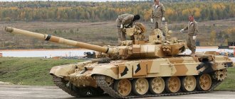
Transport and combat helicopter - TTT and TP , transport and combat helicopter. In 1966, the USSR Army adopted the lightly armored BMP-1 tracked infantry fighting vehicle, armed with a 2A28 73 mm cannon, a coaxial PKT machine gun, a 9M14M Malyutka ATGM and capable of carrying 8 soldiers with personal weapons, including 9K32 MANPADS. Strela-2". The landing force could fire from personal weapons and MANPADS on the move. The appearance of infantry fighting vehicles led to a fundamental change in battle tactics - the mobility, firepower and protection of ground forces units in the offensive and in active defense increased. Based on this, as well as the experience of small wars of the 1950s...1960s. military experts proposed developing a transport and combat helicopter that would have similar combat properties. Then “ground and flying infantry fighting vehicles” would form a complementary combat complex of the ground forces.
March 29, 1967 The military-industrial complex under the Council of Ministers of the USSR, on behalf of the 1st Deputy Minister of Defense A.A. Grechko issued an order on the development of tactical and technical requirements by the Central Research Institute-30 of the Ministry of Defense, and by the specialized enterprises of GKAT - a technical proposal for a new transport and combat helicopter.
The order was received by the manufacturing companies:
- Moscow Helicopter Plant (Chief Designer M.L. Mil);
- Ukhtomsk Helicopter Plant (Chief Designer N.I. Kamov).
It was supposed to select a helicopter for arming the AA Air Force based on a comparison of the results of the SGI.
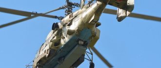
The Ka-25F army transport and combat helicopter was also developed by the UVZ team N.I. Kamova. The picture shows a flying laboratory for testing its weapons Photo: https://www.russianhelicopters.aero/ru/press/news/foto/helicopters/Ka-25_prototype_2.jpg
TsNII-30 of the USSR Ministry of Defense prepared technical specifications, which involved solving the following problems:
- destruction of enemy personnel, strong points and equipment (including main battle tanks of all types) on the battlefield and in the tactical depth of defense;
- high-speed transfer and landing of 8 soldiers with standard weapons and light equipment attached to them, incl. through zones of radioactive and chemical contamination;
- landing of reconnaissance and sabotage groups;
- evacuation and high-speed transportation of two lying and two sitting wounded with one medical worker.
When solving these problems, it was necessary to ensure the achievement of the following flight performance data:
- horizontal flight speed 320-350 km/h at extremely low altitudes (under ISA conditions);
- the ability to maneuver with an overload of up to 1.75 at speeds of 100...250 km/h, perform turns, forced and combat turns with a roll of over 45 degrees, roller coasters, dives at an angle of up to 30 degrees;
- static ceiling when hovering 3000 m under ISA conditions and 1500...2000 m at a temperature of +25°C.
The flight performance had to exceed the level of the Mi-8 and UH-1B/C helicopters.
The armament was supposed to include:
- GSh-23 cannon;
- anti-tank missile system "Sturm" with supersonic ATGM "Cocoon" with semi-automatic command radio guidance (launch range up to 5 km, the ability to destroy enemy MBTs with active armor);
- serial NAR units of 57 mm caliber and newly developed 80 and 122 mm;
- aerial bombs of up to 500 kg caliber with the nomenclature of the Su-7 fighter-bomber;
- RBC caliber 250 and 500 kg and KMG-U cassettes, equipped with small-caliber bombs and mines of various types with a caliber of 0.5 kg and more;
- the ability to fire from personal small arms of transported soldiers along the sides, back and down.
It was necessary to ensure increased survivability due to structural strength, pressurization of tanks with inert gas and their protection, duplication and redundancy, local reservation and protection by less important units of the crew and systems, the serviceability of which is necessary to continue the flight.
It was also necessary to include in the design the possibility of creating a number of modifications on its basis: a reconnaissance aircraft, an REP helicopter and others.
According to these requirements, UVZ presented a project for the Ka-25F helicopter - a modification of the ship-based Ka-25B anti-submarine helicopter with changes only in weapons and equipment, and modifications to the airframe were due only to these changes (mainly, they were a simplification of the design - less new equipment was installed than was removed old). This reduced the cost of R&D and expected mass production, but did not allow the TTT to be satisfied.
OKB MVZ developed several preliminary designs, of which two went into full-scale development - V-22 and V-24, see below. The general and direct management of their design was carried out by the Chief Designer of the Design Bureau, Mikhail Leontievich Mil. Although they used individual solutions and even entire components, assemblies and systems borrowed from the design of the Mi-8 and Mi-14 helicopters, these were fundamentally new types.
General designer of the Moscow Helicopter Plant and immediate supervisor of the Mi-24 design, Doctor of Technical Sciences Mikhail Leontievich Mil Photo: https://topwar.ru/uploads/posts/2013-03/1364321686_1.jpg
V-22 1TV3-117 preliminary design and full-scale model , transport and combat helicopter. The cost center was designed in accordance with the Order of the USSR Ministry of Defense.
General design features:
- normal take-off weight 7.0 t;
- the helicopter is made according to the classical design;
- power plant consisting of one TV2-117 engine with a take-off power of 2000 hp, AI-9 APU, VR-22 main gearbox, NV, RV transmission and its gearboxes and the RV itself, as well as systems;
- general layout similar to the B-8 helicopter in the first single-engine version with a reduction in size and the differences indicated below;
- crew of two in a common cabin;
- the landing force is located in a compartment separated from the cockpit by a partition with a door and with side doors on both sides;
- non-retractable skid-type chassis.
The technical proposal was drawn up in 1967. A full-scale model of the helicopter was built.
Based on the results of the defense of the project and the full-scale model, the B-22 project was not accepted. Its main drawback was the insufficient power of the power plant, which did not provide the required specific indicators to achieve the required flight data with the given weapons and landing force.
V-24 2TV3-117 preliminary design and full-scale model , transport and combat helicopter. The cost center was designed in accordance with the Order of the USSR Ministry of Defense.
General design features:
- normal take-off weight 10.5 tons;
- the helicopter is made according to the classical design;
- power plant consisting of two TV2-117 engines with a take-off power of 2000 hp, AI-9 APU, VR-24 main gearbox, NV, RV transmission and its gearboxes and the RV itself, as well as systems;
- general layout similar to the B-8 helicopter in the first single-engine version with a reduction in size and the differences indicated below;
- crew of two in a common cabin;
- the landing force is located in a compartment separated from the cockpit by a partition with a door and with side doors on both sides;
- non-retractable skid-type chassis.
The technical proposal was drawn up in 1967, in the same year a full-scale model of the helicopter was built and their defense took place. Although the Customer made a number of significant comments on the project (for example, the skid landing gear made it extremely difficult for the helicopter to move around the airfield without taking off, which was used in everyday operation).
In the first half of 1968, the technical requirements for a transport and combat helicopter were agreed upon by the USSR Ground Forces and the USSR Air Force at the level at which they were formed.
On May 6, 1968, based on the results of the defense of the preliminary design and full-scale model, a joint Resolution of the CPSU Central Committee and the USSR Council of Ministers was issued on the detailed design and trial construction of the B-24 transport and combat helicopter, see below.
V-24 2TV3-117, working design and full-scale mock-up . General management of the project and resolution of technical issues was carried out personally by the General Designer of the Cost Center M.L. Mil, direct management and resolution of organizational issues was carried out by his deputy - Chief Designer V.A. Kuznetsov, V.M. was appointed leading designer - responsible for fulfilling the work schedule, interaction of the design bureau teams and the entire design bureau with other organizations, MAP and the Customer. Olshevets. Marat Nikolaevich Tishchenko, from 1970 to 1990, General Designer of the Cost Center, actively participated in all these types of work.
Mikhail Nikolaevich Tishchenko - General Designer of the Moscow Helicopter Plant from 1970 to 1990. From the very beginning he participated in the creation of the Mi-24, brought it to mass production and led the process of its modernization Photo: https://www.russianhelicopters.aero/ru/press /news/2015-03-13/
Third-party organizations participated in the development of the project:
- GC Scientific Research Institute of the Air Force - determination of the cabin layout, development of aircraft, aids to navigation, instrumentation, operational issues;
- Research Institute AS MAP - issues of combat effectiveness and survivability, ATGM;
- Research Institute ERAT - issues of operation, survivability and repair, camouflage;
- TsAGI - aerodynamics and selection of NV profiles, fuselage aerodynamics, experimental testing - purging, strength, frequency and vibration tests;
- OKB Zavod im. V.Ya. Klimov (ZIK, Leningrad) - developed the TV3-117 engine and the VR-24 main gearbox for the V-24 helicopter, etc.
General features of the helicopter, technologies and materials used:
- the helicopter is made according to the classical design, but has a developed wing, made from the experience of testing the Mi-6 helicopter and serving to unload the airborne weapons when performing horizontal flight at high speed and maneuvers with positive overloads, the wing also serves to accommodate part of the outboard weapons, see below;
Side view of the B-24 transport and combat helicopter. Drawing from the book Sekach N. Mi-24 combat helicopter. M. "Exprint", -2001
- the helicopter is technologically divided into units (see below), which in turn consist of assembly units and parts manufactured and assembled in the PShM system;
- the ability to quickly remove the NV, RV and wing for transporting the helicopter by various modes of transport is provided;
- All-metal helicopter airframe;
- duralumin D16T, forging aluminum alloys AK4T, AK6, V65P, V95T in various heat treatment options (sheets, plates, rods, stampings and profiles) are used for the manufacture of spars for NV and RV blades, parts of the power set, skins experiencing large distributed, medium and small concentrated load brackets and control wiring components;
- aluminum casting alloys of the AL series in various heat treatment options are used for the manufacture of parts of systems experiencing medium and small concentrated loads: brackets and control wiring elements;
- magnesium casting alloys of the ML series are used for the manufacture of parts that experience distributed loads: brackets and rockers for control wiring and other systems;
- structural steel 30KhGSA (sheets, plates, rods, forgings, stampings and profiles) are used for the manufacture of parts experiencing large concentrated loads - attachment points for control system units, wings, landing gear, etc.;
- structural steel 35KhGSL (castings) are used for the manufacture of parts experiencing medium concentrated loads;
- Stainless steel (sheets) are used for the manufacture of parts subject to heat, hydraulic pressure and exposure to aggressive agents (power plant, pipelines, etc.);
- stainless steel (foil) is used for the manufacture of honeycomb cores of three-layer panels (connected to their skins by soldering);
- special highly hardened steels are used for local armoring (see below);
- fiberglass (sheets, rods) are used for the manufacture of decorative and internal protective panels, fastenings for equipment;
- fluoroplastic F4 is used for the manufacture of parts experiencing excessive friction;
- special armored glass (triplex) is used to make the front panel of the cockpit;
- silicate glass is used to make the two upper panels of the cockpit;
- plexiglass will be used for the manufacture of side panels of the cockpit, windows of its doors and the landing cabin;
- oil- and fuel-resistant rubbers are used in helicopter systems;
- heat-resistant rubbers are used in the power plant, in door and hatch seals;
- to obtain thin skins of variable thickness (corresponding to the current local stresses), chemical milling (etching) is used;
- the main types of connections are rivet (mainly with a two-way approach - with the exception of units with low building height) and bolted (in highly loaded places), but welding, gluing and adhesive-welded connections are also used;
- For resource-loaded parts (for example, NV side members), vibration strengthening is used (creating a cold-worked surface layer by blowing a stream of air with steel balls).
Power point:
- The power plant consists of main engines, the main gearbox, the NV, RV, its transmission, the APU and control systems, starting, fuel, oil, cooling, starting, stopping, etc., some of the power plant units are also involved in controlling the helicopter;
General view of the TV3-117 engine designed by S.P. Izotov Photo: https://studfiles.net/preview/7094316/
- two main gas turbine engines TV3-117 (take-off power 1700 hp, 2200 hp power is used in case of failure of one engine) installed above the NChF side parallel to the PSS with the bows tilted down 4° 30′ forward and the plane passing through the axes both engines 2° ±30′ to the right to connect them at right angles to the main gearbox, inclined relative to the PSS and SGF at the same angles;
- frontal air intakes, non-adjustable, circular cross-section with rounded leading edges;
Engine air intakes and main gearbox air intakes. The photo shows the Mil Mi-24A (ed. 245 with extended cabin) gray. No. 2201407, which was used as a teaching aid at the Riga Higher Military Aviation Engineering School - RVVIAU Photo: https://igor113.livejournal.com/1004998.html
Nozzle on the training-split engine TV3-117. Inside you can see the working shaft in the fairing transmitting rotation to the main gearbox and the disk of the free turbine. Photo by I.A. Gulyasa
- the nozzles (which are part of the engine) are tipped to the side through the sides of their compartments;
- the hood flaps tilt to the side on hinges and are held in place by cables; you can stand on them when servicing and repairing engines without removing them from the helicopter;
- the main gearbox VR-24 is three-stage, reduces the engine speed of 1500 rpm at a nominal value to 240 rpm for the NV and to 3237 for the propeller shaft RV, its length is 1210 mm, width 885 mm, height 1765 mm, weight 830 kg;
- the gearbox ensures the operation of both engines with limited modes, as well as one engine in the PD mode when the other fails, is installed above the SChF in the area of the landing cabin, has an oil cooling system that fills its crankcases, and a forced air cooling system, the air intake of which is located above engines, and the air exits and excess heat is removed through the cracks on the hood;
- The variable-pitch NV is five-blade, it was designed on the basis of the Mi-8 NV with the same profile, but in order to prevent an increase in air speeds at the maximum forward speed of the helicopter (its increase was expected to be about 50...100 km/h) and the expansion of the zone of supersonic flows, its diameter was reduced by 2988 mm, the swept area decreased by 92.9 sq.m and, to maintain traction, the chords of the blades were increased by 200 mm, increasing the fill factor of the swept area;
- The NV consists of a bushing with a swashplate and blades on hinged suspensions, ensuring their displacement within established limits back and forth and up and down, as well as changing the installation angle according to the commands of the swashplate;
- the HB bushing with swashplate and other systems has a height of 340 mm, a diameter of 1744 mm and a weight of 590 kg;
Main rotor hub on the Mi-24A helicopter, ser. No. 2201407 Photo: https://igor113.livejournal.com/1004998.html
- the blade has a NACA230 aerodynamic profile, which was slightly modified for production reasons; in plan view, its short butt part has a moderate positive sweep, the main part is rectangular with a large aspect ratio, and the tip is teardrop-shaped;
- the blade design includes a butt part, a spar, which is its leading edge, a counterweight to give the blade the necessary balancing and eliminate aeroelastic vibrations, 18 tail sections connected at the ends by liners, a tail stringer and a tip;
- the spar is a solid pressed shaped tube made of aluminum alloy, its upper and lower flanges have stiffening ribs, the first ribs from the toe serve as guides for the assembled counterweight, its ends are closed with covers, the butt cover has a plug connector for the contour light and a valve for pumping air into the cavity spar, on its rear part near the butt there is an indicator for a drop in air pressure (which indicates damage to the spar);
- each part of the counterweight is covered with a layer of rubber to ensure tight installation and eliminate corrosion from friction against the spar;
Main rotor blades of the Mi-24A helicopter (ed. 245 with extended cabin) gray. No. 2201407 Photo: https://igor113.livejournal.com/1004998.html
- the tail section of the blade is a three-layer panel of two thin skins made of aluminum alloy and honeycomb core, it is connected to the spar and the end stringer of the blade with glue;
- a contour light lamp is installed at the tip of the NV blade;
- according to the test results, to balance the effects caused by deviations from the theoretical contour, two trim plates were installed on each blade, which were bent manually after assessing the behavior of a particular helicopter in the first flights;
- blade set weight 580 kg;
- the NV shaft is inclined at angles of 4° 30′ forward and 2° ±30′ to the right to ensure aerodynamic symmetry of the helicopter at cruising speed;
- The APU of the AI-9V gas turbine type is installed behind the main gearbox perpendicular to the PSS and provides starting of the main engines without connecting an airfield power source or AUV and in flight (with normal charging of the on-board battery), as well as powering all helicopter systems on the ground and in case of failure of the main generators in flight ;
- air is supplied to the APU through the slots in the skin panel opposite its air intake on the starboard side, and the exhaust is supplied through the nozzle on the left side;
- the RV transmission takes place in the engine compartment, tail and keel beams and consists of a transfer case and two angular gearboxes, as well as cardan shafts;
- the RV transmission gearbox reduces its rotation speed from 3237 (propeller shaft) to 1112 rpm at the nominal engine mode (1500 rpm);
- The three-blade variable pitch propeller is the same in design as on the Mi-8 helicopter, installed on the superstructure on the right side of the keel beam;
The tail rotor on the right side of the keel beam of the Mi-24A helicopter (ed. 245 with an extended cabin) gray. No. 2201407 Photo: https://igor113.livejournal.com/1004998.html
- The fuel system consists of 5 insert soft fuel tanks (No. 1 and 2 - consumables, placement of tanks - see the fuselage design, means of increasing survivability are described in the corresponding section) with a total capacity of 2250 l, two additional fuel tanks with a capacity of 1030 l each, located in the compartment landing (used for hauling), refueling, production and draining subsystems with their pipelines, valves, taps, necks, filters and fittings;
- each engine has an independent fuel supply system from its own or the opposite supply tank in the event of failure of one of them;
- each tank is enclosed in its own container, which has a three-layer honeycomb bottom panel;
- fuel - kerosene T-1, TS-1 or T-7P;
- filling the engine oil system - 6...9 l, main gearbox - 41...50 l, oil used - B-9V.
Fuselage:
- the fuselage is a streamlined body of variable cross-section - close to a pentagon in the bow, rectangular with an oval upper part in the middle and elliptical, turning into the profile of the keel beam - in the HChF;
- technologically it consists of bow and central parts, tail and keel beams;
- in the forward part of the fuselage there is a crew cabin with its equipment and control systems for the helicopter and its systems, a machine gun mount, anti-tank systems guidance equipment, a fire pit and some equipment - instrumentation, communications, oxygen, etc.;
- in the front part of the cockpit along the PSS there is a seat for the pilot - weapon operator (hereinafter referred to as the operator), behind him from the left of the PSS is the pilot’s seat, and to the right of it is the flight engineer’s seat;
- the cockpit glazing frame is a rigid frame assembled from extruded profiles, its right front part is reinforced with additional duralumin profiles with an insert;
B-24 installation series with the fuselage in its original form with a short cockpit and side-opening entrance doors. This machine was used to test the end installations of ATGMs, and then it was used as a training tool. The helicopter was removed on the eve of disposal at the aircraft dismantling base in the early 1990s. Photo by A.Yu. Oblamsky
- in the middle part of the fuselage measuring 6057x1700x2470 mm there is a landing cabin, engine compartments, main gearbox, APU, fuel tanks, secondary control niches, various systems and control wiring;
- in the area of the landing cabin, consumable tanks No. 1 and 2 and a vertical fuel tank No. 3 are located in containers under its ceiling, tanks No. 4 and 5 are installed in containers under the cabin floor;
- on the SChF power frames there are mounting brackets for the wing consoles in their upper parts and ATGM launchers in the lower parts;
- KSS of the bow and central parts, which after assembly are permanently connected - a beam-stringer semi-monocoque with a load-bearing floor and ceiling, armored plates of the crew cabin are bolted and included in its power circuit;
- the strength set of the floor and ceiling of the landing cabin consists of edging, longitudinal and transverse beams and skins, connected into a single package, the strength and rigidity of which is ensured mainly by its significant construction height, which allows it to effectively absorb tangential stresses, transforming distributed and concentrated loads into them;
- the side panels of the fuselage consist of skins, frames and stringers; they are glue-welded;
- crew and troop cabins are sealed with pressurization from SCR and cut-off of the outside air supply to overcome zones of chemical and radioactive contamination;
Serial helicopter Mil Mi-24A (ed. 245 with extended cabin) gray. No. 2201407 – view of the middle part of the fuselage, which was the same on the experimental aircraft, but the wing had changed Photo: https://igor113.livejournal.com/1004998.html
- the flight deck has one door on the left side, it is separated from the landing cabin by a partition with a door (the door was not installed on the built helicopter);
- in the landing cabin there are two doors - 1,155x1,235 m on the left side and 1,085x1,235 on the right side, each door consists of an upper and lower part with a horizontal connector, which open and close simultaneously manually;
- in the landing cabin there are 4 windows on each side (including 2 in the upper part of the door), they can be opened for firing from personal weapons of the landing force (for convenience, 6 windows have brackets that allow you to install AK-47 assault rifles in them , AK-74 or AKM and their modifications, as well as RPK light machine guns;
- tail boom 4990 mm long, conical, tapering into an oval-section tail;
- KSS tail boom - stringer semi-monocoque, consisting of frames, stringers, hatch edgings and working skin;
- the tail boom houses the avionics and electrical systems, the radio transmission, the GO control wiring and the ANO power cables, as well as the automatic control system;
- The KSS of the keel beam is similar to the tail boom, with the exception of its shape of the rib structure and the superstructure of the RV.
Wing:
- has a load-bearing asymmetrical aerodynamic profile with a large positive installation angle, in plan view the shape is trapezoidal, tapering towards the tips, the sweep along the ¼ chord line is close to zero, there is no transverse V;
- consists of two glasses attached to the power frames of the SChF with ear-fork assemblies;
- the power set of the spectacles consists of spars, stringers, edge profiles, ordinary and power ribs, as well as working skin, control surfaces and mechanization; the wing does not have any mechanization;
- the junction of each glasses and the side of the SSF is closed by a fairing (fairing), which has a complex spatial shape and consists of front and rear parts
The first experimental B-24 helicopter had a straight wing without a transverse V Photo: https://igor113.livejournal.com/1004998.html
Horizontal tail:
- installed slightly above the axis of the tail boom in its rear part, all-moving, has a thin symmetrical aerodynamic profile, in plan view the shape is trapezoidal, tapering towards the tips, sweep along the ¼ chord line is close to zero, there is no transverse V;
- consists of two consoles attached to the load-bearing frames of the beam on a rotation shaft attached to their spars;
- The power set of the GO console consists of a spar, an edge profile, side and ordinary ribs, metal sheathing of the forehead and fabric sheathing of the spar part, it does not have control surfaces or mechanization.
Tail and keel booms of the Mi-24A helicopter (edition 245 with extended cabin) gray. No. 2201407, as well as its horizontal tail Photo: https://igor113.livejournal.com/1004998.html
Vertical tail (keel beam):
- installed along the PSS of the tail boom in its rear part, motionless, has a thick asymmetrical aerodynamic profile with a pronounced conical twist (the installation angle of the end section is 6° to the right of the PSS), in plan view the shape is trapezoidal, tapering towards the tips and significant sweep;
- the power set of the VO console consists of a spar, an edge profile, power and ordinary ribs, reinforcements for RV transmission units, as well as working casing, control surfaces and mechanization;
- an add-on for fastening the RV gearbox is installed on the keel beam.
The end of the technical description of the B-24 helicopter, its detailed tactical and technical data according to the Air Force specifications, the project and those obtained during testing of experimental B-24 helicopters, see the next part of the article
The meaning of the definitions, concepts and abbreviations used in the article and tables can be found out by opening our short dictionary on aviation and rocketry
The list of sources used will be published in the final part of the section of the Handbook on Mi-24, Mi-25 and Mi-35 helicopters
Found a typo? Select a fragment and press Ctrl+Enter.
Tags: Directory A.A. Grechko Bell AH-1G “Hyukobra” Bell UH-1 “Hugh” B-24 helicopter M.L. Mil Mi-24 Ministry of Defense of the USSR
Previous article T901-GE-900 turboshaft engine for UH-60 Black Hawk and AH-64 Apache helicopters: radical improvements
Next article Gear and Merlin helicopter. How engineers saved the Royal Navy £12 million
Provided by SendPulse
Like 1
Model
To create a detailed model of this formidable attack helicopter, we brought in top military experts and experienced modelers. Thanks to diagrams, original documents from military archives and 3D scanning of the Mi-24 helicopter, specialists created a 3D image of it. Based on the 3D model of the helicopter, an assembly design was prepared and a full set of cast metal parts was created. Thanks to this technique, you will be able to assemble a realistic and accurate 1:24 scale model.
- Accurate die-cast metal model.
- Incredible detail.
- Realistic cockpit.
- Full armament of an attack helicopter.
- Removable rockets.
- Signal lights.
When your model is finished, you will be able to admire all its details, exactly reproducing the elements of the original:
Crew cabin
. The opening door of the cabin and the transparent roof that folds up makes it possible to see all the details, the instrument panel and the armored seat.
Cargo compartment details
. The portholes of the cargo compartment open. This allows soldiers sitting in a helicopter to shoot at ground targets. The cargo compartment, used to transport soldiers or cargo, is illuminated by a single white light lamp.
Rotating propellers
. The five-bladed main rotor and the three-bladed tail rotor, located on the tail of the helicopter, rotate freely.
Movable stabilizer
. A movable tail stabilizer regulates the pitch of the Mi-24 in flight. The stabilizer of the model can be moved up and down.
Running lights
. The red light at the end of the left wing and the green light at the end of the right wing enable other aircraft to assess the Mi-24's flight direction at night and in bad weather.
White lights
. A white light underneath the helicopter illuminates the ground to help the Mi-24 land in the dark. White light indicators on both sides of the nose are necessary for airfield workers to guide the helicopter through unlit areas.
Chassis
. The nose and main landing gear are retracted into flight position and hidden behind the doors.
Model size
: Length – 75 cm. Height – 20 cm. Width – 30 cm. Main rotor diameter – 74 cm. Scale – 1:24