(AKS74N), AKS74UN, ACC, machine guns RPKN-1 (RPKSN-1), RPK74N (RPKS74N), PKMN-1 (PKMCH-1), sniper rifles SVDN-1, VSS, hand-held anti-tank grenade launcher RPG-7N1 (RPG-7DN1 ) and observation of the battlefield in natural night light conditions.
The NSPU-3 night sight is operated at ambient temperatures from plus 50 to minus 50 degrees and relative humidity no more than 98% at a temperature of 40 degrees. On a clear moonless night with natural night illumination and a transparent atmosphere, when targets are located against the backdrop of an open green meadow, it provides target detection and targeted shooting at direct shot ranges from all types of weapons indicated above.
The identification range provided by the NSPU-3 sight depends on the amount of natural night illumination, the transparency of the atmosphere and the contrast between the target and the background. In increased illumination, on a moonlit night in the presence of external illumination, if the target is located on a light background (sand, snow), the identification range increases.
In low light conditions, low clouds, reduced atmospheric transparency, if the target is located against a dark background (arable land, tree trunks, etc.), the identification range is reduced. The following types of power sources are used to power the NSPU-3 sight: five batteries D-0.55S GOST 11258-79, section 5RTs83X FSh0.351.929TU.
General design of the sight of the unified night NSPU-3.
The main components of the NSPU-3 sight are the lens, the electron-optical converter (EOC) U1, the eyepiece, and height and direction adjustment mechanisms. The sight has the following controls: reticle BRIGHTNESS OFF handwheel for turning on the sight and adjusting the reticle brightness, DOWN STP UP handwheel for the height alignment mechanism, LEFT STP RIGHT handwheel for the directional alignment mechanism, and the image intensifier focusing ring.
A desiccant, a nipple covered with a lid, a lid covering the battery, and a clamping device are attached to the sight body. There is a plug in the eyepiece part of the body and an eyecup is attached. The dehumidifier is designed to dry the air inside the scope during operation. Unsaturated silica gel desiccant has a bluish color. When completely saturated with moisture, silica gel acquires a pale pink or off-white color, which indicates the unsuitability of silica gel for further use.
The nipple is used for purging the internal cavity of the sight with dry nitrogen or air. When purging, nitrogen or air comes out through a hole closed with a plug. The NSPU-3 sight is mounted on a weapon using a clamping device consisting of a bracket, a clamping screw, a latch, a handle, and a handle. The eyecup facilitates the orientation of the eye relative to the exit pupil of the sight and protects the eye from accidental damage.
The focus ring of the image intensifier is designed to obtain a clearer image of the target at different identification ranges, when aligned with a calibrated target, and to compensate for defocusing of the image intensifier when the temperature changes from minus 50 to plus 50 degrees. The main power source of the NSPU-3 sight is a rechargeable battery consisting of five D-0.55S GOST 11258-79 batteries connected in series. The backup power source for the NSPU-3 sight is the 5РЦ83Х ФШ0.351.929ТУ section installed in the container.
Purpose and design of the NSPU sight
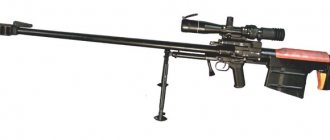
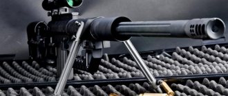
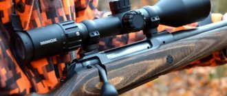
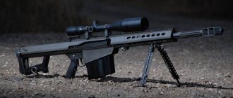
72. The NSPU sight (universal night rifle sight) is installed on the AKMN (AKMSN), AK74N (AKS74N) assault rifles, RPKN (RPKSN), RPK74N (RPKS74N) machine guns, PKMN (PKMSN), SVDN sniper rifle, RPG-7N hand-held anti-tank grenade launcher ( RPG-7DN) (Fig. 52).
The NSPU sight is designed to detect targets and conduct aimed fire at them at direct shot ranges from all of the above weapons. With increased illumination (on a moonlit night, in the presence of external lights), the visibility range increases; in low light conditions (low clouds, reduced atmospheric transparency), the visibility range decreases.
The weight of the sight in the combat position is 2.2 kg, in the stowed position - 3.5 kg. The sight magnification is 3.5x. Field of view 5°40″ Resolution 1.8″. The operating time of the sight with one battery is about 6 hours. At low air temperatures, the operating time of the sight is reduced.
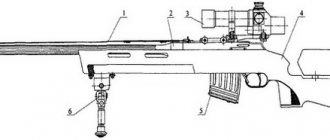
Rice. 52. NSPU sight on the weapon:
a - automatically; b - on a light machine gun; c - on a Kalashnikov machine gun: d - on a sniper rifle; c - on a hand-held anti-tank grenade launcher
73. The NSPU sight (Fig. 53) consists of a body, a lens, an aiming angle mechanism, a voltage converter, a high-voltage adjustment unit, an eyepiece, a battery, a diaphragm and a light filter.
74. The sight body is designed to accommodate and assemble all parts and mechanisms of the sight and attach it to the weapon. The lens is screwed into the front part of the sight body, and the eyepiece is screwed into the back. Inside the case there are: in the cylindrical part - an electron-optical converter in the base, which is pressed in with a lid; a shock-absorbing ring is installed between the lid and the image intensifier; in the thickened part and below in a box with a lid - a voltage converter, a high-voltage unit, a voltage divider and a compartment with a lid for the battery.
The electrical connection of the voltage converter with the high-voltage unit is carried out by an adapter. To measure the voltage of the high-voltage unit, there is a hole in the cover, closed with a plug with a rubber gasket and a washer.
The cover is attached to the body with screws. The eyepiece frame with lenses is screwed into the lid. An eyecup is placed on the protrusion of the lid, which is clamped with a spring ring.
The aiming angle mechanism is attached to the front of the case on the left with screws and fixed with pins. Voltage is supplied to the light bulb through a wire and contact
Rice. 53. NSPU sight:
a - general view; b - section: 1 - diaphragm; 2 — guide (LEFT, STP, RIGHT); 3 - light bulb; 4 - wire; 5 — body; 6 — drying cartridge; 7 — eyecup;
8 - latch; 9 - cover; 10 — bracket; 11 — handle; 12 — stopper; 13 — clamping screw; 14 — reticle brightness handwheel OFF; 15 - cover; 16 — handwheel;
17 — scale; 15, 20, 29 and 33 - lenses; 19, 21, 23 and 28 - frames; 25 - converter; 26 - cover; 27 — shock absorber; 30 - plug; 31 high voltage units;
32 — aiming angle mechanism
The sight is mounted on a weapon using a clamping device, which consists of a bracket, a clamping screw, a latch, a stopper and a handle.
75. The lens is screwed into the front part of the sight frame. In frames 23 (Fig. 53) with aperture holes designed to reduce the influence of scattered light, which degrades the quality of the target image, there are lenses 22 and 24. Both frames are fixed in a common frame, which is screwed into the body and secured with screws. Lens 20 with a prism in the frame is secured in the body with screws, and lens 18 is secured with a ring.
76. The aiming angle mechanism (Fig. 54) is located in the housing. A lens in a frame is screwed into the body, and an AR-90° prism and a leash are attached to the guide. The spring presses the leash against the guide (LEFT, RIGHT, STP). One end of the spring is fixed in the guide, the other in the bushing. When the guide is rotated, the AP-90° prism rotates, as a result of which the reticle image in the field of view shifts to the left or right relative to the optical axis of the sight—the sight is aligned in direction.
Rice. 54. Aiming angle mechanism
1 — Guide LEV, STP, RIGHT; 2 - nut; 3 and 11 — bushings; 4 — clamp; 5 - spring; 6 - guide; 7 — body; 8 - gasket; 9 — light bulb;
10 and 12 — contacts; 13 — bar; 14 — mesh in the frame; 15 — prism in a frame; 16 - spring; 17 — prism guide; 18 — pin; 19 - nut; 20 — alignment screw;
21 — scale; 22 - screw; 23 — handwheel UP, STP, DOWN; 24 - 24 and 25 - limit washers; 26 - key; 27 — leash; 28 — prism AR-90°; 29 — lenses in the frame;
30 - bushing; 31 - body
When the handwheel is turned UP, STP, DOWN and the alignment screw, the prism guide moves along the key, and the prism in the frame and the reticle move along with it, i.e. the image of the reticle in the field of view shifts up and down relative to the optical axis of the sight - inputs are entered into the sight aiming angles, and with the screws unscrewed 1-2 turns, the height of the aisle is adjusted.
The directional alignment scale printed on the nut has 30 divisions; the price of one division is 0-00.5. Each rotation of the guide by one division is recorded.
The aiming angle scale is graduated in hundreds of meters. The sight kit includes a set of aiming angle scales: for AKMN (AKMSN) assault rifles, RPK74N (RPKS74N) machine guns, RPKN (RPKSN) - with graduations from 3 to 7; for AK74N (AKS74N) assault rifles, PKMN (PKMSN) machine guns, SVDN sniper rifle - with graduations from 4 to 10; for RPG-7N (RPG-7DN) grenade launchers - with “+” and “—” signs
The weapon sample is engraved directly on the scale. One of the scales is installed on the sight, the rest of the scales are stored in the storage box.
Each rotation of the handwheel by one division is recorded. The handwheel has a height adjustment scale with a division value of 0-00.5
The direction of rotation of the handwheel and guide is indicated by arrows with inscriptions.
The sight reticle (Fig. 55) serves for aiming and can be used to determine the range to local objects and targets.
There are aiming marks on the reticle. The upper row of aiming marks is designed for aiming when firing from RPG-7N (RPG-7DN) grenade launchers up to 300 m and when firing from other types of weapons at all ranges according to the aiming angle scales. The strokes marked with the number 4 serve for aiming when firing from a grenade launcher at a distance of 400 m, and the bottom stroke - at 500 m.
Rice. 55. View of the field of view of the NSPU sight
The light bulb for illuminating the reticle is screwed into the body of the aiming angle mechanism
77. The electron-optical converter with a voltage divider (Fig. 56) is placed in a casing, which, together with the protective glass, provides electrical isolation of the image intensifier from the metal parts of the sight. The casing is closed with a screen that protects the image intensifier from electromagnetic interference. The divider contacts are placed on the corresponding converter rods. A shock absorber is installed between the converter and the casing.
Rice. 56. Electron-optical converter:
1 — screen; 2 - casing; 3 — image intensifier; 4 - voltage divider; 5 — shock absorber; 6 — protective glass; 7 - board with photoresistor
The voltage at the high-voltage inputs (bars) of the image intensifier tube from the photocathode to the screen of the third camera is distributed according to the 0-10-20-30 kV scheme
The divider distributes the voltage across the rings of the electron-optical converter and is made of nine resistors, three of which serve to protect the image intensifier from failure when illuminated by the flames of shots and shell explosions.
78. The voltage converter is designed to convert the DC voltage of 2.5 V of the battery into an AC voltage of 6 kV. The assembled converter (transformer, panel with transistors and resistors) is mounted in the lower compartment of the sight body.
79. The high-voltage unit is designed to rectify and multiply the 6 kV AC voltage converter into a 30 kV DC voltage. It consists of 14 selenium rectifiers connected in series, 3 or 2 in each arm, and 6 capacitors. All elements of the high-voltage block are filled with compound, forming a single block.
80. The adjustment unit (Fig. 57) is designed to turn the aisle on and off, set the required initial brightness of the reticle illumination light bulb, and to automatically adjust the brightness of the screen and reticle when natural night illumination changes.
There is a resistor on the board attached to the cover. The microswitch and pusher are attached to the stand, and the stand is attached to the cover. The second end of the pusher touches the lower end of the cap.
Handwheel BRIGHTNESS GRID, OFF connected to the cap. The movable part of the resistor is also connected to it through a bushing, ring and pin.
With the sight turned off, when setting the arrow on the handwheel against the inscription OFF. the end of the pusher is located in the recess at the end of the cap. When the handwheel is turned clockwise, the pusher comes out of the recess and presses the microswitch contact, thereby turning on the sight. By further turning the handwheel, the required initial brightness of the reticle illumination lamp is set.
Rice. 57. Adjustment block:
1 - cover; 2 — handwheel BRIGHTNESS GRID, OFF; 3 - bushing; 4 - ring; 5 - check; 6 - screw;
7 - cap; 8 — clamp; 9 - resistor; 10 - microswitch; 12 — pusher; 12 - board
In extreme positions, the rotation of the handwheel is limited by a protrusion in the board. The position of the handwheel is fixed with a lock.
81. The eyepiece is screwed into the back of the aisle body. The purpose and design of the eyepiece are set out in Art. 14 of this Guide.
In the eyepiece part of the sight there is a drying screw, consisting of a nipple (plug), a cover and a rubber gasket. The drying screw is used to dry the inner strip of the sight with dry nitrogen or air. When blowing, nitrogen or air comes out through a hole, which is closed with a plug with a rubber gasket and a washer.
During operation, the air inside the sight is constantly dried by the silica gel of the drying cartridge. Silica gel saturated with moisture has a bluish color. As it becomes saturated with moisture, the color of the silica gel changes and, when completely saturated, has a pale pink or off-white color.
The condition of the silica gel can be viewed through the desiccant glass.
82. The 2NKBN-1.5 battery is the power source for the sight. Battery capacity is 1.5 Ah. The sight's power is turned on by a microswitch, which is mechanically connected to the resistor's handwheel. The design and operation of batteries are set out in Art. 8.
83. The diaphragm (Fig. 58) protects the sight from flare when aligning it during the day (at dusk), as well as when shooting during high night illumination. The amount of light entering the scope is limited and controlled by an iris diaphragm and two neutral density filters.
Rice. 58. Aperture:
1 — light filters; 2 - movable ring; 3 - spring; 4 — clamp; 5 — body; 6 — clamp; 7 — oil seal; 8 - petal
The diaphragm, consisting of petals, is located between the filters.
At the end of the body there are the inscriptions OTK., CLOSED. which correspond to a fully open or closed iris diaphragm.
When the movable ring rotates, the movement is transmitted to the blades, while the light opening increases or decreases (depending on the direction of rotation), thereby adjusting the light opening of the aperture.
To prevent spontaneous opening or closing of the diaphragm, a latch with a spring is installed in the movable ring. Fixation is carried out using teeth located on the inner surface of the movable ring. The diaphragm is placed on the main body of the sight and secured with a pin that fits into the grooves of the diaphragm body.
Rice. 59. Light filter in frame:
1 - spring; 2 - good; 3 - light filter
84. A light filter in the frame (Fig. 59) serves to increase the contrast of the target image when it is observed against a green background in high light conditions. The light filter is attached to the protrusions of the aisle body in the same way as the diaphragm is attached.
Rice. 60. Sight accessories:
1 - storage box; 2 — bag for carrying the sight; 5 - diaphragm; 4 - key; 5 - battery;
6 — eyecup; 7 - napkin; 8 - belt; 9 — light filter in the frame; 10 — scales; 11 — cassette; 12 — light bulbs
85. The scope accessory (Fig. 60) includes a stowage box, a bag for carrying the scope and spare parts (battery, diaphragm, filter in the frame, eyecup, napkin, key, drying cartridge in a glass, belt, scales, cassette with light bulbs) .
The purpose of the stowage box, bag and spare parts are the same as for the PPN-2 sight.
The sighting reticle of the unified night sight NSPU-3.
In the field of view of the NSPU-3 sight (with angular dimensions in thousandths), aiming marks are applied on the reticle, the top row of which is used for aiming when firing from an RPG-7N (RPG-7DN) grenade launcher up to 300 meters and when firing from other types of weapons, specified in section 2 of this instruction, at all ranges according to the aiming angle scales.
The strokes marked with the number 4 are used for aiming when firing from a grenade launcher at a distance of 400 meters. The bottom line is at 500 meters. When firing a PG-7L grenade from a grenade launcher, the top row of aiming marks serves to aim at a distance of 150 meters. The strokes marked 2L are for aiming at a distance of 200 meters and the bottom stroke is for 300 meters.