The mobility of the infantryman is one of the most important components in modern warfare. How quickly a soldier can get to the desired area of the theater of operations largely determines the outcome of the entire operation. After all, the art of war is the ability to concentrate one’s forces in a certain place. Infantry firepower is also important. In many ways, these functions in modern conflict are performed by an infantry fighting vehicle. Today this armored vehicle is one of the most important types of armored vehicles.
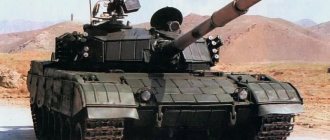
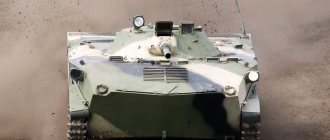
At the moment, the main infantry fighting vehicle in service with the Russian army is the BMP-2, which, in fact, is a deep modernization of the BMP-1 - the first vehicle of this class in the world.
Technical characteristics of the BMP-2 model 1980
- Years of production: 1980-1990.
- Total manufactured - about 15,000 pieces. all modifications.
- Combat use - military conflicts of the second half of the 20th century, the war in Afghanistan.
- Crew – 3 people, landing party – 7 people.
- Combat weight - 14 tons.
- Length – 6.74 m, width – 3.15 m, height – 2.1 m, ground clearance – 420 mm.
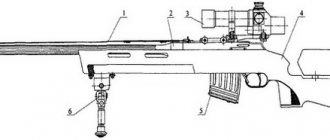
- Armament: 30-mm cannon (ammunition - 500 shells); four ATGMs “Fagot”/”Konkurs”; MANPADS “Strela-3″ / RMG-7 grenade launcher. 7.62 mm machine gun (ammunition - 2000 rounds).
- Armor thickness – 6-26 mm.
- Diesel engine, power – 300 hp.
- The maximum speed on the highway is 65 km/h, afloat – 7 km/h.
- Cruising range on the highway is 600 km.
- Obstacles to overcome: wall – 0.7 m, ditch – 2.5 m.
Lubricating the bearing of the main clutch release mechanism
Tools, accessories and operating materials: keys 1012, 1417, syringe press with hose (Fig. 54), syringe press rod (Fig. 67), tip (Fig. 64) and Litol-24 lubricant.
For lubrication you need:
– unscrew the bolts securing the ribbed sheet of the body and lift it until it is installed on the stopper;
– unscrew the four bolts securing the cover (3) (Fig. 25) of the main clutch hatch and remove the cover;
– turn the bearing housing (13) so that the oiler (9) is in the upper position. Connect the plunger syringe press hose to the main clutch bearing oiler;
– fill the bearing of the main clutch release mechanism with grease (about 60 g). Check the amount of lubricant to be filled according to the markings marked on the rod of the syringe press;
– disconnect the syringe press hose from the oiler (9);
– install the main clutch hatch cover in place and secure it with four bolts;
– install the ribbed sheet of the housing in place and secure it.
2nd question: Design and operation of the gearbox and control drive.
The power transmission serves to transmit and change the magnitude of torque from the engine to the drive wheels in magnitude and direction, and also provides starting, turning, braking of the machine and protecting the engine from overloads in the event of a sharp increase in movement resistance.
The power transmission of the machine is mechanical, with a stepwise change in gear ratios. It consists of a lubrication and hydraulic control system, a main clutch, a gearbox, two planetary rotation mechanisms, stopping brakes, control drives, and two final drives.
The main clutch, gearbox and planetary rotation mechanisms are placed in a common crankcase and rigidly connected to the engine, forming a power unit mounted on two yokes and a rubber support on the bottom of the machine.
The power transmission is shown in Fig. 23.
To ensure normal operating conditions of the power transmission and reliable controllability of the machine, it is necessary:
– timely, fully and efficiently carry out all maintenance work within the time limits established by the operating instructions;
– securely tighten and cotter plugs for filling, checking the level and draining lubricant from the units;
– avoid prolonged slipping and overheating of the clutch discs,
Rice. 23. Power transmission (section)
1 – stopping brake drum; 2 – brake of the sun gear of the turning mechanism; 3 – planetary gear of the turning mechanism; 4 – locking clutch of the rotation mechanism; 5 – third gear gear; 6 – 2nd gear gear; 7 – reverse gear; 8 – 1st gear gear; 9 – driven bevel gear; 10 – driven shaft; 11 – 4th gear gear; 12 – 5th gear gear; 13 – load shaft; 14 – connecting shaft; 15 – drive shaft with final drive sun gear; 16 – satellite; 17 – final drive housing with epicyclic gear; 18 – driven shaft with carrier; 19 – drive wheel; 20 – synchronizer; 21 – engine crankshaft; 22 – main clutch; 23 – main clutch release mechanism; 24 – oil pump drive shaft; 25 – drive shaft; 26 – reverse intermediate gear
– do not operate the machine with faulty or unadjusted control drives and with incorrect adjustments of units and mechanisms;
– when starting the car, changing gears, turning, braking and moving afloat, follow the driving rules.
Power transmission lubrication and hydraulic control system (Fig. 24)
designed to turn off the main clutch, turn on the friction elements of the PMP, facilitate gear shifting in the gearbox, lubricate the rubbing surfaces of bearings, gears, cotters, gear shift forks and other parts of the gearbox and planetary turning mechanisms, as well as to tighten the stopping brake bands.
Rice. 24. Power transmission lubrication and hydraulic control system
1 – hydraulic cylinder of the left stopping brake; 2 – pipeline to the hydraulic cylinder of the left stopping brake; 3 – right turn spool lever; 4 – left turn spool lever; 5 – stop brake spool lever; 6 – servo booster for gearbox II and III gears; 7 – main clutch spool lever; 8 – pressure gauge of the power transmission lubrication system; 9 – pressure gauge receiver: 10 – flexible hose; 11 – pipeline to the hydraulic cylinder of the right stopping brake; 15 – hydraulic cylinder of the right stopping brake; 13 – servo booster for 4th and 5th gears; 14 – bypass valve; 15 – valve for smooth activation of the main clutch: 16 – gearbox breather; 17 – oil cooler; 18 – filler plug with oil level indicator (dipstick); 19 – valve box; 20 – pipeline from the hydrocyclone to the valve box; 21, 22 – oil pump drive rollers; 23 – pressure reducing valve; 24 – driven gear of the oil pump; 25 – drive gear of the oil pump; 26 – tubes for supplying lubricant to the synchronizer fork of 4th and 5th gears; 27 – channel for supplying lubricant to the bearing of the reverse intermediate gear; 28 – reverse intermediate gear; 29 – pipeline for supplying lubricant to the synchronizer fork for 2nd and 3rd gears; 30 – driven shaft of the gearbox; 31 – gearbox load shaft; 32 – synchronizer: 33 – oil pump; 34 – oil filter – hydrocyclone; 35 – lubricant supply pipeline to the gearbox driven shaft; 36 – left turning mechanism; 37 – spool box
The system includes the following components:
oil pump (33) (Fig. 24), oil filter-hydrocyclone (34), valve box (19), main clutch smooth valve (15), spool box (37), gear shift servo boosters (6 and 13), oil radiator (17), bypass valve (14) and pipelines.
History of the creation of the BMP-2
The first attempts to make an armored vehicle that would transport infantry behind tanks were made at the end of the First World War. At that time, automobile technology was imperfect and slow-moving, so this idea was abandoned for a while. She again became interested in the military before the start of World War II. It was clear to everyone that the coming conflict would be a war of mechanized formations, which required mandatory infantry support.
The development of such machines was carried out both in Germany and in the USSR. The Germans created a half-track open armored personnel carrier that delivered infantry to the battlefield and could provide them with fire support. However, the most active work on the infantry fighting vehicle began after the Second World War, starting in the mid-50s.
The tactics of that time involved the active use of nuclear weapons in combat operations. The military needed a vehicle that could protect the crew and infantrymen from the damaging factors of a nuclear explosion.
In 1966, the BMP-1, the first vehicle of this class in the world, was adopted by the Soviet Army. The BMP-1 turned out to be mobile and maneuverable; the armor reliably protected the crew from shrapnel and small arms fire. The crew was protected from the effects of weapons of mass destruction. This car had excellent technical characteristics; it was equipped with a very successful diesel engine.
The vehicle was armed with a smooth-bore 73-mm Grom cannon, a machine gun and Malyutka guided anti-tank missiles.
The main problem of the machine was its insufficient level of security. The sub-caliber shells adopted by NATO countries penetrated the frontal armor of the BMP-1 from a distance of 1000 meters. The Bushmaster cannon, which was installed on the main American Bradley infantry fighting vehicle, could hit the BMP-1 from a distance of 2000 meters. The side armor of the vehicle was even pierced by 12.7 mm bullets.
The armament of the BMP-1 also raised many questions. The Grom smoothbore gun was created on the basis of the SPG-9 grenade launcher and had a pronounced anti-tank character. It caused criticism: short firing range, low accuracy and small vertical aiming angles. In the initial period of operation, the BMP-1 ammunition included only shells with a cumulative warhead; fragmentation ammunition was added later. To support the infantry with fire, the BMP-1 only had a machine gun, which was clearly not enough.
During the creation of the BMP-1, the USSR simply did not have a small-caliber, rapid-fire gun that could be installed on this vehicle. An automatic 30 mm cannon that could be used on this vehicle only appeared in the mid-70s. In 1974, work began on modernizing the vehicle at the Kurgan plant, where the BMP-1 was produced.
The military looked at the possible reduction in the caliber of the gun without much enthusiasm. Tests were carried out during which a 30-mm cannon fired at a tank. It was unable to penetrate the armor, but the tank lost its combat effectiveness: the turret was jammed, all attachments were destroyed, and the external fuel tanks caught fire.
We decided to manufacture a new vehicle, which will be armed with a new weapon. In 1980, the new infantry fighting vehicle BMP-2 was put into service. Initially, its production volume was supposed to be 10% of the BMP-1 production volume. But soon the war began in Afghanistan, which decided the fate of this armored vehicle. Even before the official adoption of the BMP-2, several dozen of these vehicles were sent to Afghanistan.
The BMP-2 automatic cannon, which has large elevation angles, was perfectly suited to the conditions of that war. She could conduct effective fire on the enemy occupying positions at commanding heights. Almost immediately, army workshops began installing additional screens on the vehicle to increase its protection against heavy small arms fire. A little later, this work began to be performed at the manufacturing plant. This is how a modification of the vehicle appeared - BMP-2D. The greatest losses of the BMP-2 in Afghanistan were caused by hand-held anti-tank grenade launchers.
Later, the BMP-2 took part in many more conflicts: in Iraq, the North Caucasus, and Karabakh. The machine almost always showed its high technical characteristics, reliability and ease of operation. Numerous modifications have been created on its basis, which usually differ in weapon system and additional armor. BMP-2 is used today in many armies of the world.
Checking the filling and refilling the gearbox with oil:
Tools, accessories and operating materials:
wrench, extension, replaceable head (27), funnel with filter, nozzle (Fig. 66), rags, bucket, oil.
To check refueling and refueling it is necessary;
– clean the plug (1) (Fig. 3) from dust and dirt and unscrew it;
– wipe the area around the dipstick with a rag, remove the dipstick. If the oil level on the dipstick is below the bottom mark of the dipstick, top up the gearbox with oil by inserting a funnel with a nozzle and a filter into the hole for the dipstick. Use a bucket to fill the gearbox housing with oil up to the top mark of the dipstick;
– place the probe in place so that the flat on the probe head goes beyond the protrusion on the cover;
– screw in plug 1.
Check the oil level in the gearbox no earlier than 15 minutes after stopping the engine.
Device
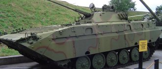
BMP-2 is, in fact, a deeply modernized BMP-1. Both of these combat vehicles are 80% identical. The BMP-2 has the same layout as its predecessor. The engine and power compartment are located at the front, the control compartment is also located there, and the fighting compartment is in the very center of the vehicle. At the rear there is a troop compartment that can accommodate six paratroopers. The entire rear part of the vehicle is occupied by doors designed for landing infantrymen.
The vehicle's armor is rolled and welded. The armor protects the crew and paratroopers from shrapnel, small arms fire and weapons of mass destruction. The troop compartment has special embrasures equipped with ball mounts that allow firing from personal weapons. The landing compartment is divided into two parts by a fuel tank.
The main difference between the BMP-2 and the BMP-1 is the weapon system. The new vehicle is equipped with an automatic 30-mm 2A42 cannon with 500 rounds of ammunition. Thanks to this gun, which has a large elevation angle, the BMP-2 can fire at low-flying air targets. The rate of fire of 2A42 is up to 550 rounds per minute. A machine gun was also installed on the BMP-2, and the Fagot or Kornet ATGMs can be used on the vehicle to destroy armored vehicles.
To install new weapons on the BMP-2, a new, more spacious turret was equipped. The gun is stabilized in two planes; this device allows it to fire on the move. The turret has seats for the gunner and vehicle commander. Thanks to new, more advanced sighting devices and observation devices, both the vehicle commander and the gunner can now fire.
Compared to the previous vehicle, the number of paratroopers and their placement have changed. The landing compartment can accommodate six soldiers, and there is another place for an infantryman behind the driver.
The BMP-2 has a more advanced engine with a turbocharging system. The design of the chassis and transmission remained the same. A more advanced smoke screen installation system has been added, which consists of thermal smoke equipment and six “Tucha” smoke grenade launchers. The machine is equipped with a fire extinguishing system.
The installation of a new larger turret increased the weight of the vehicle, however, the BMP-2, like the BMP-1, can float. The speed of movement on water is 7 km/h, the movement occurs due to the rewinding of the tracks.
Video about BMP-2
I announce the topic and place of the next lesson on the subject
5Organizational and methodological instructions:
- Prepare the specified material support in the classroom.
- On the eve of the lesson, approve the lesson plan.
- When studying the device, the main thing to pay attention to is those system parameters, knowledge of which is necessary for proper operation of the power plant.
MAIN PART:
1st question: Purpose and general design of the main clutch.