Introduction
The technical description and operating instructions are intended to study the design and operating rules of the modernized unified night sight NSPUM for small arms and hand-held anti-tank grenade launchers (index 1PN58), hereinafter abbreviated as “sight”.
When studying the sight, you must additionally use the following documents: “Manual on shooting” (for each type of weapon, respectively), “RPG-7V hand-held anti-tank grenade launcher. Service manual, “Operating instructions FYUZ.585.452I for battery D-0.55S GOST 11258-79”, “Operating instructions for section 5РЦ83Х ФШ0.351.929 TU”, “Instructions for using the group spare parts kit ALZ.812.106 TO, appendix 3".
Characteristics of devices with image intensifier tubes of different generations
Generation 1 and 1+ devices
They have basic functionality and low cost. They are characterized by a low light gain, so they are equipped with powerful infrared illumination. Models 1 are sensitive to flare, and the image of the picture appears blurry at the edges.
Models 1+ are equipped with special anti-light protection and show a clearer picture. They are resistant to the recoil of large-caliber small arms, and are mainly used at ranges up to 150 meters. Due to their cost, these devices are popular among amateur hunters.
Devices of generation 2 and 2+
More in demand among professional hunters because:
- perform their functions even in poor lighting conditions, including on a dark moonless night;
- there is protection against flare of the visual field;
- have a long range: at a distance of 600 meters you can recognize an object, and at a distance of 300 meters you can conduct targeted fire;
- There is no image distortion at all;
- More suitable for use in open areas.
These devices provide high shooting efficiency and hit accuracy. Withstands the recoil of weapons of any caliber.
3rd generation devices
The 3rd generation night sights are considered the most advanced and functional. They have a high cost, but are fully justified because they provide the user with great opportunities.
The electron-optical converter is equipped with a photocathode and high-aperture optics. The system works perfectly without infrared illumination even in the lowest visibility conditions. The device has a high resolution, which makes the picture clear even with a magnification of 5x or higher. Precision fire can be conducted at a distance of up to 500 meters, and observations up to 900 meters.
The night sight has small dimensions and weight. Mainly used by professional hunters.
Night sights
Night sights
The ability to conduct combat operations at night, in conditions of limited visibility, has always been valued. And one of the main problems here has always been the ability to conduct aimed fire. The importance of night sights is evidenced by their constant mention in assessments of the experience of the second Chechen campaign.
Removable flashlights mounted on weapons, luminescent attachments or inserts for mechanical sighting devices were offered at the beginning of the 20th century. But the real solution lay in a different region of the spectrum - infrared. The infrared (IR) region of the spectrum occupies the wavelength range from 0.7 to 3 microns (near or “short-wave” zone of the IR range) and from 3 to 5 microns (the beginning of the middle zone of the IR range). The operation of such optical-electronic devices is based on the principle of converting an IR image into a visible one. The basis of the design is an electron-optical converter (OOC), the general circuit of which was developed back in the 1930s by V.K. Zvorykin. The operation of OOP is based on the phenomenon of external photoelectric effect. It is known that the light flow can be considered both as an electromagnetic wave and as a flow of particles - quanta. The ability of quanta to “knock out” electrons from the surface of a substance determines the photoelectric effect, and the “yield” of electrons depends on the density and intensity of the light flux. The wave properties of light appear depending on the sensitivity of the substance to the photoelectric effect on the length of the light waves.
The image intensifier tube is an electric vacuum device with a translucent photocathode on the front wall and a luminescent screen on the back wall. IR rays falling on the photocathode knock out electrons from it, which are accelerated by the electric field, focused by an electron lens formed by special electrodes, and rush to the screen. Hitting the screen, they cause it to glow greenish. This is how a “picture” visible to the eye is formed on the screen.
Diagram of a three-chamber image intensifier with fiber optic systems: I, II, III – first, second and third amplification stages; 1 – IR radiation, 2 – fiber-optic input window, 3 – focusing electrodes, 4 – fiber-optic connecting board, 5 – fiber-optic output window, 6 – visible range output image, phosphor (luminescent screen)
To obtain a sufficiently bright image, it is necessary to either illuminate the area with an IR spotlight, or additionally enhance the brightness provided by the radiation of the night sky, the light of stars, and the Moon.
The first method is used by so-called “active” night vision devices (“zero generation devices,” as they are sometimes called). These included the American “Sniper” and the German “Vampire” from the Second World War. Both included a “telescope” with an image intensifier tube, an IR illuminator and a wearable power supply with a voltage of about 30 kV. With a magnification factor of 4x to 6x, the devices operated at a range of up to 60 m, i.e. at close combat ranges.
This early stage in the development of night vision devices was characterized by the use of image intensifier tubes with an oxygen-silver-cesium or oxygen-silver-zinc photocathode and spotlights based on an electric lamp and an IR filter.
The zero-generation image intensifier tubes remained in service for quite a long time - the same “Sniper”, for example, remained in service with the armies of a number of countries back in the 1960s. But by that time, such disadvantages of active sights as significant size and weight, the unmasking effect of an IR illuminator, and the formation of interference from dust or fog at the edges of the field of view were no longer tolerable.
Among passive (illuminated) devices with enhanced natural night illumination, several generations are distinguished, differing primarily in the type of electron-optical converters. Here it is worth remembering what some of the following characteristics mean. Thus, the light amplification factor shows how many times the light flux observed at the exit from the PN B eyepiece exceeds the light flux entering the input of the optical system of the device from the object of observation. As for optical-mechanical devices, for optical-electronic devices one of the main characteristics is resolution. The resolution of devices that include an image intensifier is often assessed not in angular values, but by the number of alternating light and dark lines (stroke) that fit 1 mm of the test object. Resolution depends on both the optical system of the device and the resolution of the image intensifier.
So, in backlit devices of the first generation (I) there is a multi-stage brightness enhancement (this was already a significant step forward compared to the image intensifier tube according to the Zvorykin scheme). The first non-illuminated cascade night vision devices were still large in size due to the need for cooling the image intensifier and high-voltage power supplies. The decisive shift here was associated with the introduction of a multi-alkali photocathode, which had greater sensitivity, several orders of magnitude lower dark current and did not require cooling. Together with further work on optics and miniaturization of power supplies, this made it possible to create new shooting sights and at the same time fit the entire sight complex into one housing.
The operating principle of an amplifier on a microchannel plate:
1 – photocathode, 2 – microchannel plate, 3 – fluorescent screen, 4 – microchannel wall, 5 – electrode, 6 – output electron flow, 7 – primary electron entry, 8 – secondary electrons
In our country, the NVD system of this generation was formed by the end of the 1960s. The NSP-3 night sight for the assault rifle was also included in this system. Nevertheless, the first generation image intensifier tube was characterized by a number of disadvantages. They gave an insufficiently bright and contrasting “picture”. The resolution was very uneven - 25–36 lines per millimeter in the center and 5 lines per millimeter at the edge of the field of view. The sights were very sensitive to exposure to bright light sources - for example, the flash of a shot. And the glass cylinders of the image intensifier tube were sensitive to the recoil impulse of the weapon.
Further improvements associated with increasing the IR sensitivity and noise immunity of devices, increasing the field of view, etc., led to the appearance in the 1970s of new NVGs of the same generation, which included the NSPU night universal shooting sight (1PN34, topic " Alpha") with a three-stage image intensifier. To protect against light exposure, it uses an iris (petal) diaphragm. To increase the contrast of the image when observing against a green background in high light conditions, use a red filter; in weak fog or haze, use a yellow filter. The sight weight is 2.2 kg, the magnification factor is 3.5x, the field of view angle is 5.4°. NSPU allows you to fire at night at a direct weapon range. On a moonlit night or when using backlighting, the range increases; in low clouds and smoke, it decreases. Improvement of the image intensifier and the transition in the electrical part to a small-sized element base made it possible to make the NVD lighter and more economical (and the time of continuous operation of the device on one battery increases the autonomy of the unit) - an example of this is the 1PN58 unified sight.
As an analogue, we can mention the American AN/PVS-2, also made on the basis of a three-stage image intensifier tube with electrostatic focusing. The magnification factor of this sight is 4x, field of view is 10.4–10.7°, weight is 2.6 kg, range, depending on illumination, is 300–400 m. To increase the energy of light rays entering the device input, and thus reducing the axial length of the sight, mirror-lens lenses are also used, such as, for example, in the German “Orion-80”.
In the “1+” generation image intensifier tubes, metal and ceramics were already used, and to form an image and interface the screens and photocathodes of adjacent converters, wrapping devices based on plates of fiber-optic elements were introduced (fiber optics was already used in the mentioned AN/PVS-2). The efficiency of amplifiers and image clarity have increased. Resistance to recoil impulse has increased significantly. The resolution has also increased - up to 50 lines per millimeter in the center of the field of view and up to 28 at the edges. As we can see, the ratio between the resolution in the middle part of the “picture” and at its edges has improved.
Electron-optical converter of the third generation with a gallium arsenide photocathode: 1 – photocathode, 2 – microchannel plate, 3 – screen, 4 – fiber-optic system for 180° image rotation, 5 – power supply
The second generation (II) consisted of devices with an amplifier on a microchannel plate (MCP), which appeared in the 1970s. The MCP is a flat disk made of semiconductor material with many channels, the inner surface of which is coated with a substance that has secondary electron emission. Electrons knocked out from the photocathode enter the open end of the microchannel, knocking out secondary electrons from the walls. That is, each microchannel of the MCP works as a photomultiplier, which exponentially increases the number of ejected electrons. The diameter and number of channels are selected based on the best resolution and strength of the MCP. The diameter of the channels was hundredths of a millimeter. The brightness gain increased by more than 20 times compared to generation “1+” - for generation “1+” it did not exceed 1000, for generation “II” it reached 20,000. Resolution increased to 30–50 lines per millimeter almost everywhere field of view. The image distortions characteristic of generations “I” and “1+” have disappeared, and automatic adjustment of image brightness has appeared. The advantage of the brightness amplifier on the MCP is also its lower sensitivity to flare - the MCP “localizes” light interference without causing illumination of the entire field of view. In addition, the use of MCP reduces the size of the device.
Passive sights on MCP include the domestic NSPU-3 (1PN51), which provides reliable detection of a person at a distance of up to 300–600 m. NSPU-3 weight – 2.1 kg (together with a 6.25 V power supply), total length – 340 mm, magnification ratio for NSPU-3 is 3.6x, field of view angle is 9.5°.
Generation II also includes the American AN/PVS-3A with a 4x magnification, a field of view of 10°, a weight of 1.45 kg and a length of 330 mm. The sight provides shooting against manpower at a range of up to 150–250 m. And the English M1500, with a magnification factor of 3x, a weight of 1 kg and a length of 265 mm, is effective at a range of up to 500 m.
In the mid-1990s, NVGs based on the P+ generation image intensifier tubes appeared. The creation of multi-alkali photocathodes with increased sensitivity and improvement of optical systems made it possible in this generation to qualitatively improve the characteristics of amplification-type devices and increase the resolution - at least 45 lines per millimeter. Moreover, high resolution was maintained even in low light (starlight, for example). It is now possible to use luminous aiming marks.
The P+ generation image intensifier tube is used, for example, in the export sight NV/S-17, offered by BelOMO for automatic small arms. Weighing 1.2 kg, this scope has a magnification of 3.5x and a field of view of 12°.
The “II Super” generation of image intensifier tubes is distinguished by an even greater sensitivity of the photocathode and a resolution of about 55 lines per millimeter.
Reducing the size and power consumption of image intensifier tubes has made it possible to produce night sights for small arms in smaller dimensions and weighing less than 1 kg.
Non-illuminated night sights have also come to “commercial” weapons. An example of this is the PON-5 sight with an electro-optical converter of the 1st generation, with illuminated reticle
The modular design principle has made it possible to create new families of night sights for various types of weapons - such as the Russian sights of the 1PN93 series, including the 1PN93-3 sight for use with the SVD sniper rifle. On the other hand, it became possible to use night sights as a “night attachment” to an optical sight mounted on a weapon.
The dependence of the range and image quality of amplifying type NVDs on the level of natural light does not allow us to forget about the need to supplement the devices with illuminators. True, now these are miniature modules built directly into the NVD housing based on IR semiconductor lasers or LEDs.
For example, the Russian unified sight NSPU-5 (1PN83), made on the basis of a generation II image intensifier tube, has an IR laser illuminator (“illuminator”) built into the body. The diameter of the illuminated zone at a distance of 300 m is 5–6 m. In combination with automatic brightness adjustment and the brightness of the aiming mark adjustable by the shooter, this makes it possible to work in a wide range of external conditions - from full moon nights (when natural night light is sufficient) to almost complete darkness, identifying a “full-length man” type target at a range of up to 300 m. The magnification factor of the NSPU-5 is 3x, field of view is 7°, sight weight is 1.45 kg, length is 300 mm.
Meanwhile, back in the mid-1980s, photocathodes with photosensitive material based on gallium arsenide appeared, which had greater sensitivity and “yield” of electrons. Their use in combination with new vacuum technologies made it possible to create generation III image intensifier tubes, also using MCP. The spectral sensitivity of the image intensifier has shifted slightly further into the IR range, and this has increased the image contrast. At the same time, the optical system was improved in order to more fully realize the advantages of the new generation of image intensifier tubes. The sensitivity of generation III NVGs has increased by more than a third, and the resolution has also increased, so that they can operate at lower light levels (on dark nights, in underground structures without lighting). The range has increased by 30%, so that the effective firing range at night is closer to that during the day.
Already in the last years of the 20th century. devices of the “III+” generation appeared with sensitivity doubled compared to the “III” generation and a resolution of 55 lines per millimeter or more.
The next step was thermal imaging devices (TIIs), used since the 1970s. These devices “translate” into the visible region of the spectrum not reflected rays, but the own thermal radiation of people, equipment, and active devices. This radiation occupies a significant part of the IR range, sometimes called the “thermal IR range”. The spectral ranges of 3–5 μm and 8–14 μm have found application, corresponding to relatively wide “transparency windows” - regions of the spectrum in which the transmission of rays by the atmosphere is better. In addition, the maximum thermal radiation of the human body occurs approximately at a wavelength of 9.3 microns. The photodetectors used operate in these ranges. The range of action of TPVP does not depend on the level of natural night illumination; they remain operational in conditions of illumination by intense light sources. Thermal radiation spreads well in conditions of reduced transparency of the atmosphere, smoke, through networks, branches, and this allows the TPVP to work in fog and detect camouflaged targets when setting up conventional smoke screens. Since the intensity and spectrum of thermal radiation emitted by a heated body depend on the properties of the body and its temperature, the image is quite contrasty and allows you to highlight the desired object against the background of other heated bodies, although the resulting image is less familiar to perception than the image formed by an intensifying type NVD.
To capture the thermal radiation of objects, arrays of miniature detectors are used, which convert IR signals into electrical signals, which are fed to a pre-amplifier. Here they are multiplied and converted into a complex video signal using a logic circuit. The development and widespread use of thermal imaging devices was facilitated by the rapid development of microprocessor technology, digital methods of signal processing and visualization. Portable thermal imaging devices have already found application in reconnaissance equipment complexes, in tank fire control systems, in anti-tank systems, and with rifle sights the matter is a little more complicated. Although thermal imaging sights are already included in standard and large-caliber sniper rifles and are offered for machine guns and grenade launchers, their price is still many times higher than the price of the weapon itself. Opportunities for improving the characteristics of TPVPs, including reducing their size, weight and energy consumption, are expected, in particular, from replacing the detector arrays and the optical-mechanical image scanning system with devices based on focal-plane matrices (using charge-coupled devices) that do not require such mechanical scanning and deep cooling devices. However, you should not trust statements about TPVP as an “absolute means of observation and aiming” - although thermal imaging does allow you to detect targets behind light cover, it does not provide “vision through any walls”.
Of interest are combined (with two or more channels, but a single input) and complex (with separate channel inputs) day/night sights that meet the requirements of all-weather, 24-hour operation and high noise immunity. Thus, in a French sight, the day branch is located above the night branch, and its image is projected onto the eyepiece through a mirror and prism. A tube with an image intensifier tube of generations “II” or “III” can be used as a night branch. In the “modular sighting system” F7201 of the American company ITT, the generation “III” image intensifier module can be inserted between the tube with the reticle and the eyepiece of the optical sight. An example of a domestic combined sight is POND-4. The sight uses an image intensifier tube of the “P+” generation with direct image transfer, a multi-alkaline photocathode and an amplifier on the MCP, and automatic brightness adjustment. The magnification factor of both channels is 5x, field of view is 6.5° (“day”) and 8° (“night”), sight weight is 1.75 kg, power source voltage is 3 V. Channels are switched using a lever.
Next, we will look at a number of in-service and experienced sniper rifles from around the world.
Functional diagram
The sight is an electro-optical device that operates at night.
Operation at night is ensured by an electron-optical converter (EOC), which enhances the brightness of the observed objects. The low-brightness target image is projected by lens 1 () onto the photocathode of the image intensifier tube L1, located in the focal plane of the lens. The image, amplified in brightness, is viewed on the image intensifier screen through eyepiece 2. Reticle 3 with aiming marks is projected onto the photocathode of the image intensifier through a lens and a prism and is illuminated by LED D1.
The image (with angular dimensions in thousandths) shows a view of the sight's field of view.
The reticle contains aiming marks, the top row of which is used for aiming when firing from an RPG-7N2 (RPG-7DN2) grenade launcher up to 300 m and when firing from other types of weapons at all ranges according to the aiming angle scales. The strokes marked with the number 4 serve for aiming when firing from a grenade launcher at a distance of 400 m, and the bottom stroke - at 500 m.
When firing a PG-7L grenade, the upper row of aiming marks is used for aiming at a distance of 150 m, the strokes marked with the number 2L are for aiming at 200 m, and the bottom stroke is for aiming at 300 m.
For ease of use, the sight has automatic reticle brightness adjustment (ARYAS, ), provided by photoresistor R2 located in front of the image intensifier screen, the signal from which is supplied to ARYAS, which allows maintaining the required brightness of the reticle throughout the entire illumination range. In addition, the sight has a manual adjustment of the reticle brightness, carried out by potentiometer R1, kinematically connected to the handwheel BRIGHTNESS RETILE OFF.
When the GRID BRIGHTNESS OFF handwheel, mechanically connected to microswitch B1, is turned on, a voltage from a power source of 6.25 V is applied to the circuit. The stabilized voltage converter (SPN) produces packets of alternating voltage pulses of 1250 V, lasting about 1.5 ms with a pulse duration in a packet of 0.4 ms and a packet repetition rate of 30-40 Hz. This voltage is supplied to the input of the high-voltage voltage multiplier (HVM), and the constant voltage supplying the image intensifier tube (L1) and the automatic screen brightness adjustment circuit (ARB) and protection from light interference is removed from the output of the HVU. The work of the ARNEA boils down to the following.
With increasing illumination in the area, the photocurrent through resistor B15 increases, which leads to an increase in the voltage drop across it and limiting the increase in the brightness of the image intensifier screen.
When light interference appears in the sight's field of view in the form of flames from artillery system shots and explosions of their shells, as well as in the form of white light illuminated by a searchlight, the photocurrent sharply increases. This leads to an increase in the voltage drop across resistors R14, R13, R12 and the supply of defocusing voltages to the corresponding electrodes of the image intensifier tube. Its screen goes out, i.e., the image “collapses”, due to which the image intensifier screen is resistant to intense short-term and long-term exposure to light.
After the light interference ceases, the defocusing voltages are removed and the sight’s operation resumes.
The sight remains operational when the voltage on the power source changes from 4.5 to 7.5 V.
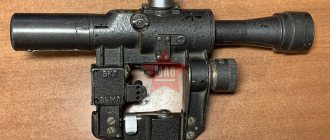
The sight (index 1PN58) is designed for observation of the battlefield and aiming when firing from AKMN2 (AKMSN2), AK74N2 (AKS74N2) machine guns, PKMN2 (PKMSN2) machine gun, RPKN2 (RPKSN2), RPK74N2 (RPKS74N2) light machine guns, RPG-7N2 grenade launcher ( RPG-7DN2) and sniper rifle SVDN2.In 1976, the development of a sight with an image intensifier power supply without a voltage divider and with a long continuous operation time began (Research and Development Institute “Vremya”). Then a unified night sight NSPUM was developed on the theme of the OCD “Hit”.
Produced at the Novosibirsk Instrument-Making Plant.
A detailed description of the device is given in Product 1PN58. Technical description and operating instructions. AL3.812.106 TO. 1985
The sight has an elongated cast body with an extended bracket. The 1st generation image intensifier tube has a fairly high gain and a reliable system of protection against external illumination. The sight allows you to recognize a full-length person in the light of the moon and stars at a distance of up to 300 meters, and has proven itself well in real combat operations. The sight is equipped with mechanisms for introducing aiming angles, alignment in height and direction, and a mechanism for adjusting the brightness of the reticle. Using a sight, you can determine the distance to a target if its size is known. The sight is operated at ambient temperatures from 50C to minus 50C and relative air humidity up to 100% at a temperature of 35C.
Technical data
| Meaning | ||
| Identification range under normal conditions for observing a tank on board | m | 600 |
| Identification range under normalized conditions for observing a soldier's height | m | 400 |
| Apparent increase | times | 3,5 |
| Angular field of an optical system in space with an object in the horizontal plane | hail | 5 |
| The angular field of the optical system in space by an object in the vertical plane | hail | 4 |
| Eye relief | mm | 50 |
| Exit pupil diameter | mm | 5 |
| Range of alignment of the aiming line in height | +- 0-08 | |
| Range of alignment of the aiming line in direction | +- 0-08 | |
| Sight supply voltage | IN | 6,25 |
| Current consumed by the scope under normal climatic conditions | mA | 7 |
| Sight dimensions | ||
| Length (without diaphragm) | mm | 458 |
| Height | mm | 186 |
| Width | mm | 99 |
| Dimensions of the storage box | ||
| Length | mm | 500 |
| Height | mm | 215 |
| Width | mm | 165 |
| Weight of the sight in firing position | kg | 2 |
| Weight of the sight in stowed position | kg | 3,3 |
| Weight of sights in a storage box with a single spare parts | kg | 7,3 |
* As a power source, instead of a battery, you can use a K-316 container with three AA-size power supplies with a voltage of 1.5V.
The modification of the sight for PKMN received the GRAU index - 1PN58-2!
Photo of the cover of the maintenance and operating instructions for modification 1PN58-2:
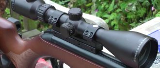
Photo of the NSPUM sight on the AK-105:
Photo comparison of sights NSPUM and NSPU:
Photo of the battery compartment and NSPUM battery:
Various options for carrying cases for sights:
Charger for batteries NSPUM:
Photo of the NSPUM reticle:
From the user description:
speron/guns.ru:
From my experience. Six months ago, people gathered at night to shoot at night. There was a Swiss PNB installed in front of the daytime optics lens from Vectonics, the states, a Belarusian one from Eloptik 2+ (with a Golan tube) and I took 1Pn58. They were all servicemen and there were two lines. At first everyone watched Vecronix, then they ran to Mon. All observations are very subjective, against the expectation that the latest technology, super radically corresponding to the price, has moved forward, but it did not really come true. The large Vectronix is very visible, but it still looks like a very fine sieve. It’s about the same with the US 3pok monocular. (I don’t write which one, it’s still a double bass) and next to them is a Belarusian. Naturally, everyone was surprised that the mon is worse, but it is visible, and if you turn on good backlighting, then in general all the differences except the overall dimensions and weight are not visible. Moreover, the image quality of the US monocular installed behind the eyepiece of the daytime optics was equal to that of the PN. Light losses appeared in daytime optics lenses. I now have an MTs-13 and for the competition I started sculpting a base for the 1pn58 night light.
IRMA/guns.ru:
In 1PN58 the flash of a shot is not visible; it has a “slow” automatic brightness adjustment. Sometimes a little haze from the exhaust of the shot is visible, especially in wet weather. The resource according to the passport is 12,500 shots, probably the shot is not very useful for the image intensifier
:
List of electrical circuit elements
| Col. | Note | ||
| Resistors | |||
| R1 | SP4-1A-47 kOhm A-12 OZHO.468.045 TU | 1 | |
| R2 | Photoresistor FPF-7-1 OS4.681.060 TU | 1 | |
| R3 | OMLT-0.125-V-100 kOhm±10% OZHO.467.107 TU | 1 | |
| R4* | OMLT-0.125-V-470 Ohm±10% OZHO.467.107 TU | 1 | 470 Ohm, 680 Ohm |
| R5 | OMLT-0.125-V-20 kOhm±10% Coolant 0.467.107 TU | 1 | |
| R6 | SPZ-19a-0.5-10Ohm±10% Coolant0.468.134 TU | 1 | |
| R7 | OMLT-0.125-V-3 kOhm±10% OZh0.467.107 TU | 1 | |
| R8 | OMLT-0.125-V-20 kOhm±10% OZh0.467.107 TU | 1 | |
| R9 | OMLT-0.125-V-750 kOhm±10% OZh0.467.107 TU | 1 | |
| R10 | OMLT-0.125-V-15 kOhm±10% OZh0.467.107 TU | 1 | |
| R11 | OMLT-0.125-V-20 kOhm±10% OZh0.467.107 TU | 1 | |
| R12 | KEV-0.5-5.1 GOhm±10% OZh0.467.077 TU | 1 | |
| R13 | KIM-E-200 MOhm±10% OZh0.467.022 TU | 1 | |
| R14 | KIM-E-22 MOhm±10% OZh0.467.022 TU | 1 | |
| R15 | KEV-0.5-1.5 GOhm±10% OZh0.467.077 TU | 1 | |
| R16 | OMLT-0.125-V-1 kOhm±10% OZh0.467.107 TU | 1 | |
| R17* | OMLT-0.125-V-47 kOhm±10% OZh0.467.107 TU | 1 | 47, 68, 82 kOhm |
| Capacitors | |||
| C1, C2 | K53-4-15-68±20% Coolant0.464.037 TU | 2 | |
| C3, C4 | K53-4-6-100±20% Coolant0.464.037 TU | 2 | |
| C5, C6 | K53-4-1.5-68±20% Coolant0.464.037 TU | 2 | |
| С7…С36 | K15-15-3 kV-1000 pF±20% Coolant0.460.170 TU | 30 | |
| B1…B5 | Battery D-0.55S GOST 11258-79 | 5 | |
| IN 1 | Microswitch MP7 OYu0.360.007 TU | 1 | |
| D1…D3 | Diode 2D102A TT3.362.074 TU | 3 | |
| D4 | LED AL307B aA0.336.076 TU | 1 | |
| D5 | Zener diode 2S147A SM3.362.805 TU | 1 | |
| D6 | Stabistor 2S119A SM3.362.816 TU | 1 | |
| D 7 | Diode 2D102A TT3.362.074 TU | 1 | |
| D8…D37 | Rectifier column 2TS1MA-1 aA0.339.008 TU | 30 | |
| L | Electro-optical converter OD0.335.221 TU | 1 | |
| T1, T2 | Transistor 2T312V ZhK3.365.143 TU | 2 | |
| T3 | Transistor 2T603B I93.365.003 TU | 1 | |
| T4 | Transistor 2P103A TF3.365.000 TU | 1 | |
| T5 | Transistor 2T603B I93.365.003 TU | 1 | |
| T6 | Transistor 1T403B SI3.365.023 TU | 1 | |
| Tr1 | Transformer TV10-1 Oyu0.471.043 TU | 1 | |
| Ш1 | Fork RSh2N-1-5 OYu0.364.002 TU | 1 | |
| Ш2 | Socket RG1N-1-1 OYu0.364.002 TU | 1 |
* Selected during regulation
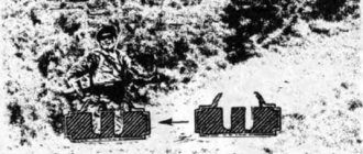
Aligning the sight on a grenade launcher
To align the grenade launcher with the sight, you must:
apply an additional circle with a diameter of 80 mm with a crosshair on the shield for alignment of mechanical and optical sights - the aiming point of the sight (TNN); the relative position of the fuel pump and the aiming point of the grenade launcher (GNG) is indicated in Fig. 6;
install the shield with the target vertically along a plumb line in front of the grenade launcher at a distance of 20 m from the aiming bar;
check the sighting devices (optical and mechanical sights), as indicated in the “Service Manual for the RPG-7V hand-held anti-tank grenade launcher.” Check the compliance of the temperature correction scale markings installed on the sight (on the RPG-7N2 and RPG-7DN2 anti-tank grenade launchers, a sight with a temperature correction scale marked RPG-7 must be installed);
install the grenade launcher on the machine to check the sighting devices of the grenade launcher;
point the adjusted optical sight at the crosshair to align the optical sight;
remove the optical sight without disrupting the grenade launcher's aiming;
install the sight on the grenade launcher and secure it without disrupting the aiming of the grenade launcher;
set scale 12 () to temperature correction “+”;
turn on the sight, making sure that aperture 14 is closed;
looking through the sight, turn the handwheel 16 and the diaphragm 14 to select the optimal brightness of the reticle and the visibility of the alignment target;
check the coincidence of the top of the aiming square of the reticle with the center of the TNV on the alignment target;
if the top of the aiming square of the reticle does not coincide with the center of the crosshair, then use key 5 () to unscrew screws 18 () one or two turns and by rotating the handwheel 17 and guide 1, align the top of the aiming square of the reticle with the center of the TNV. In this case, hold scale 12 with your hand, preventing it from moving;
screw screws 18 in completely;
check the correctness of the reconciliation;
turn off the sight.
To align the sight with the alignment target (shield) at dusk and at night, the alignment target is illuminated. If, during alignment, the image of the alignment target with the aperture fully open becomes not sharp, then increase the target illumination, while the aperture opening must be reduced.
When aligning the sight to a distant point *:
install the grenade launcher on the machine to check the sighting devices of the grenade launcher;
install an alignment optical sight on the grenade launcher and select a remote point (top of a pole, corner of a building, etc.) at a distance of at least 300 m from the grenade launcher;
set the temperature correction handwheel of the optical sight to the “+” sign;
observing through the optical sight, install the grenade launcher so that the crosshair of the remote scale of the optical sight with digitization 3 is at the edge of the distant point;
remove the optical sight from the grenade launcher without disturbing the position of the grenade launcher;
install the sight on the grenade launcher (at the same time, set handwheel 17 with scale 12 to the “+” sign);
turn on the sight;
Looking through the scope, make sure that the aiming square coincides with the selected distant point in height and direction.
If the aiming square has deviated in any direction, then it is necessary to align it with the selected point in the same way as when aligning with the shield.
After completing the verification you must:
turn off the sight;
set handwheel 17, scale 12 to the “+” position at ambient temperatures above 0°C, and at temperatures below 0°C – to the “–” position.
Maintenance #1
TO1 of a sight in operation is carried out by the shooter under the supervision of the platoon commander with the involvement, if necessary, of specialists from the workshop unit (formation).
TO1 of sights in service is carried out when the sight is received by the unit, at least once a year, when placed for short-term storage.
During TO1, the checks and work required for TeO are carried out, and additionally, plaque is removed from the contacts and the external optical surfaces are cleaned, the moisture-saturated silica gel is restored, and the stowage box is touched up.
To clean external optical surfaces, use napkin 6 (), cotton wool for the optical industry GOST 10477-75, technical rectified ethyl alcohol GOST 18300-72, petroleum ether GOST 11992-74 or a mixture (10% alcohol and 90% ether (see Appendix 1).
To remove grease from the surface of the glass, you need to wipe it with a napkin or cotton wool. In case of heavy contamination, clean as follows:
wrap a little cotton wool around the end of a wooden stick;
moisten the cotton wool in alcohol, ether or a mixture, then remove excess liquid by lightly shaking;
wipe the glass several times with dampened cotton wool without touching the frame;
change the cotton wool and make circular movements from the center to the edge to finish cleaning.
When cleaning, you should pay attention to ensure that solvents (alcohol, ether) do not get under the frame, as this will dissolve the sealing putty and destroy the seal of the sight. When placing for short-term storage, to protect against corrosion, the outer unpainted parts of the sight and spare parts must be lubricated with a layer of GOI-E GOST 3276-74 lubricant
When placing for short-term storage, to protect against corrosion, the outer unpainted parts of the sight and spare parts must be lubricated with a layer of GOI-E GOST 3276-74 lubricant.
To restore moisture-saturated silica gel, you need to unscrew the lid of the desiccant, pour the silica gel into a clean metal vessel, which is placed on a heat source (electric stove, primus stove, fire coals, etc.). Contact of silica gel with flame is unacceptable. The recovery temperature of silica gel is 150-170 °C. Silica gel is restored within 3-4 hours.
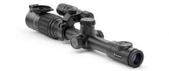
Digital night vision sights
A digital night vision sight can be used both at night and during the day, and the quality of the transmitted image does not suffer. A device with a digital matrix is not afraid of light exposure. In addition, it is equipped with useful multimedia functions: zoom with the ability to magnify up to 14 times, as well as a built-in video camera that will allow you to capture the most beautiful moments of the hunt. The detection range is 200 meters. Digital night vision sights can withstand shock loads of up to 6 thousand joules, so they can be installed on weapons of any caliber.
Some digital devices have a small drawback: the picture can slow down, so shooting at a moving target will be a bit of a problem. In this case, you will always have to give the device a little time to adjust, keeping the object at the front sight. This problem can be avoided by purchasing a device with a higher frame refresh rate.
The digital sight is a good analogue of a device with a 2nd generation image intensifier converter and at the same time has a low cost.
Back to list
Notes
- ↑ 1 2 3 Levi A.
Is it possible to know all types of automatic weapons? (Russian) // Weapons: magazine. - 2007. - September (No. 09). — P. 42-53. - [www.arms.ru/Guns/sniper/vss001.htm Description of the Vintorez sniper rifle on the website www.arms.ru
] - ↑ 1 2 Koronin Yu. N., Malinin V. V., Popov G. N.
[cyberleninka.ru/article/n/istoriya-sozdaniya-i-unifikatsii-strelkovyh-pritselov-nochnogo-videniya-na-primere-izdeliy -tskb-tochpribor History of the creation and unification of night vision rifle sights using the example of products from the Central Design Bureau "Tochpribor"] (Russian) // Interexpo Geo-Siberia: magazine. - 2008. - T. 4, No. 1. - Novikovsky E.A.
Domestic small arms, grenade launchers, hand fragmentation grenades and ammunition / Pichkovsky S.I., Skobelev A.O. - Barnaul: AltSTU, 2009. - [www.ak-info.ru/joomla/index.php/devices/9-optics/46-nspumabout Description of the NSPUM night optical sight on the website www.ak-info.ru]
- Optical-electronic systems and laser technology. Weapons and technologies of Russia. Encyclopedia. XXI century / Under the general editorship of S. Ivanov. - Moscow: Publishing House "Weapons and Technologies", 2005. - T. 11. - ISBN 5-93799-010-1.
Sight Modifications
Difference between PSO-1 and PSO-1S-1 sighting reticles
Today there are the following modifications of the PSO sight:
Military
- PSO-1 with a luminescent screen (and, accordingly, a switch) designed to detect targets manifested by infrared radiation. Illumination of the aiming reticle from a microlamp (power source 2РЦ63);
- PSO-1S without a luminescent screen with a first-generation LED and, accordingly, a 3V voltage converter;
- PSO-1M2 for targeted shooting from the Dragunov SVD sniper rifle of 7.62 caliber. Sighting scales are designed for shooting from 100 m to 1300 m. Without fluorescent screen, with 1.5 V LED and 1.5 V source;
- PSO-1M2-01 - for targeted shooting from a special sniper rifle (rifled) VSS of 9 mm caliber and a special automatic machine AC of 9 mm caliber. The sighting scales are designed for shooting from 100 m to 400 meters (50 meter increments). For shooting at dusk, the scopes have an illuminated reticle. Currently, a standard AA battery is used as a power source instead of a 2РЦ63 battery.
Civil
The civilian equivalent is the POSP sights produced by BelOMO and the PO series produced by the Oil Refinery:
- PSO-1M2-02 - modification for weapons of 12.7×107 mm caliber (limited use);
- POSP 4×24 is a modification of the PSO-1 optical sight. There is no luminescent screen or (in comparison with PSO-1M2) a built-in light filter, different markings, on the POSP 4×42T model the grid is similar to PSO-M2-01;
- POSP 6x24 - larger, 6x magnification;
- POSP 6×42 - model with 6× magnification and higher aperture;
- POSP 8x42 - the main difference from the base model is twice the apparent magnification, which corresponds to the magnification of binoculars. Compared to the original PSO-1 sample, the POSP sight has the ability to dioptrically adjust the eyepiece (POSP 8×42D) and increase the magnification (POSP 4-8×42, POSP 4-8×42D and POSP 3-9×42). In addition to this, the vertical adjustment dial on the main part of the POSP sight does not have a scale with distances as it was in the basic version, but simply has a linear digitization of “clicks” with a value of 2.5 cm per 100 meters of distance. This difference allows the sight to be used for any ammunition.
| Technical data | PSO-1 | POSP 4×24M |
| Angular field of view (degrees) | 6 | 6 |
| Eye relief (mm) | 68 | 68,2 |
| Lens luminous diameter (mm) | 24 | 24 |
| Exit pupil diameter (mm) | 6 | 6 |
| Resolution limit (arc/sec) | 12 | 12 |
| Supply voltage (V) | 1,5 | 3 |
| Overall dimensions, mm) | 337x136x72 | 337x136x72 |
| Weight (kg) | 0,62 | 0,62 |
Similar optical sights
The PSO-1 sight is recognized in world sniper practice as one of the most successful, which is why it is produced abroad in various modifications with different aiming reticles:
- Romania Romania - LPS 4×6° TIP2 optical sight manufactured by IOR;
- PRC PRC - optical sight “Type JJJ”;
- Belarus Belarus - optical sight POSP;
- Serbia Serbia - optical sight ZRAK M-76 4x 5°10' / ZRAK ON-M76;
- DPRK DPRK - optical sight "Type78";
Technical data
The main characteristics are shown in table. 1.
Table 1
| Name of characteristics | Nominal value | Note |
| 1. Identification range under normal observation conditions *, m: | ||
| tank side | 400 | |
| tall figure of a soldier | 300 | |
| 2. Apparent magnification, times | 3,5 | |
| 3. Angular field of the optical system in object space: in the horizontal plane in the vertical plane | 5°4° | |
| 4. Eye relief, mm | 50 | |
| 5. Exit pupil diameter, mm | 5 | |
| 6. Range of alignment of the aiming line: | ||
| in height | ±0-08 | |
| towards | ±0-08 | |
| 7. Sight supply voltage, V | 6,25 | |
| 8. Current consumed by the sight under normal climatic conditions, mA | 7 | |
| 9. Sight dimensions, mm: | without aperture | |
| length | 458 | |
| height | 186 | |
| width | 99 | |
| 10. Dimensions of the storage box, mm: | ||
| length | 500 | |
| height | 215 | |
| width | 165 | |
| 11. Sight weight, kg: | without aperture | |
| in combat position | 2 | |
| in a stowed position | 3,3 | |
| in a packing box with a single spare parts | 7,3 |
* The following conditions are considered normalized:
illumination level – (3-5) 10-3 lux; background – green grass; atmospheric transparency tа = 0.85.
List of faults and methods for their elimination
The list of possible malfunctions of the sight is given in table. 2.
table 2
| Malfunction | Probable Cause | Elimination methods |
| The clicks of the operating sight are faintly audible | 5РЦ83Х sections or battery are discharged | Replace power supply |
| The brightness of the image, reaching a maximum, sharply drops to very low or the image has fluctuating brightness, making it difficult to work with the scope | Light overload. Voltage converter transformer breakdown | Place the diaphragm on the lens. Send the sight to a connection repair shop |
| The image of the area is visible weakly and blurry | Fogging or contamination of the outer surfaces of the eyepiece or lens | Wipe the lens and eyepiece with a spare parts cloth |
| The image of the area is faint and blurry. Flashes and blinking are observed in the sight's field of view | Fogging of the internal surfaces of the lens, eyepiece or photocathode of the image intensifier tube | Send the sight to a connection repair shop |
| Flashes and blinking are observed in the sight's field of view | Moist air entered the scope | Blow the sight with dry nitrogen or air. Replace dryer |
| The image intensifier screen lights up, clicks of the operating converter are heard | The image intensifier is out of order | Send the sight to the connection repair shop |
| The clicks of the operating converter are not heard | The voltage converter is faulty | Send the sight to the connection repair shop |
| Dark spots appeared in the field of view of the scope, interfering with observation. | Some debris has appeared in the field of view or the image intensifier has been damaged by illumination from point light sources | Send the sight to the connection repair shop |
| When the sight is turned on, a crescent-shaped darkening is observed at the edge of the field of view and the reticle image is shifted relative to the center of the screen | The image intensifier is illuminated by a strong light source | Turn off the sight and after 1 minute, illuminate the lens side with any light source (for example, a flashlight) for 1 minute; turn on the sight; if the problem persists, send the sight to a repair shop |
| The grid image is visible, but poorly (blurred) | The image intensifier is illuminated by strong light sources | Same |
| The image is “collapsed” | Same | Turn off the sight and keep it in this state for 30 minutes, while the aperture on the sight lens should be set to the CLOSED position; turn on the sight, if the problem is not resolved, then send the sight to a repair shop |
Excerpt characterizing NSPUM
The dirty girl came out from behind the chest, tidied up her braid and, sighing, walked forward along the path with her blunt bare feet. Pierre seemed to suddenly come to life after a severe faint. He raised his head higher, his eyes lit up with the sparkle of life, and he quickly followed the girl, overtook her and went out onto Povarskaya. The entire street was covered in a cloud of black smoke. Tongues of flame burst out here and there from this cloud. A large crowd of people crowded in front of the fire. A French general stood in the middle of the street and said something to those around him. Pierre, accompanied by the girl, approached the place where the general stood; but French soldiers stopped him. “On ne passe pas, [They don’t pass here,”] a voice shouted to him. - Here, uncle! - said the girl. - We'll go through the Nikulins along the alley. Pierre turned back and walked, occasionally jumping up to keep up with her. The girl ran across the street, turned left into an alley and, after passing three houses, turned right into the gate. “Right here now,” said the girl, and, running through the yard, she opened the gate in the plank fence and, stopping, pointed to Pierre a small wooden outbuilding that burned brightly and hotly. One side of it collapsed, the other was burning, and the flames were shining brightly from under the window openings and from under the roof. When Pierre entered the gate, he was overcome with heat, and he involuntarily stopped. – Which, which is your house? - he asked. - Oh oh oh! - the girl howled, pointing to the outbuilding. “He’s the one, she’s the one who was our Vatera.” You burned, my treasure, Katechka, my beloved young lady, oh, oh! - Aniska howled at the sight of the fire, feeling the need to express her feelings. Pierre leaned towards the outbuilding, but the heat was so strong that he involuntarily described an arc around the outbuilding and found himself next to a large house, which was still burning only on one side of the roof and around which a crowd of French were swarming. Pierre at first did not understand what these French were doing, carrying something; but, seeing in front of him a Frenchman who was beating a peasant with a blunt cleaver, taking away his fox fur coat, Pierre vaguely understood that they were robbing here, but he had no time to dwell on this thought. The sound of the crackling and roar of collapsing walls and ceilings, the whistle and hiss of flames and the animated cries of the people, the sight of wavering, now scowling thick black, now soaring lightening clouds of smoke with sparkles and sometimes solid, sheaf-shaped, red, sometimes scaly golden flame moving along the walls , the sensation of heat and smoke and the speed of movement produced on Pierre their usual stimulating effect of fires. This effect was especially strong on Pierre, because Pierre suddenly, at the sight of this fire, felt freed from the thoughts that were weighing him down. He felt young, cheerful, agile and determined. He ran around the outbuilding from the side of the house and was about to run to the part of it that was still standing, when a cry of several voices was heard above his head, followed by the cracking and ringing of something heavy that fell next to him. Pierre looked around and saw the French in the windows of the house, who had thrown out a chest of drawers filled with some kind of metal things. Other French soldiers below approached the box. “Eh bien, qu'est ce qu'il veut celui la, [This one still needs something," one of the French shouted at Pierre. - Un enfant dans cette maison. N'avez vous pas vu un enfant? [The child is in this house. Have you seen the child?] - said Pierre. – Tiens, qu'est ce qu'il chante celui la? Va te promener, [What else is this interpreting? “Get to hell,” voices were heard, and one of the soldiers, apparently afraid that Pierre would take it into his head to take away the silver and bronze that were in the box, advanced threateningly towards him. - Un enfant? - the Frenchman shouted from above. – J'ai entendu piailler quelque chose au jardin. Peut etre c'est sou moutard au bonhomme. Faut etre humain, voyez vous... [Child? I heard something squeaking in the garden. Maybe it's his child. Well, it is necessary according to humanity. We are all people...] – Ou est il? Ou est il? [Where is he? Where is he?] asked Pierre. - Par ici! Par ici! [Here, here!] - the Frenchman shouted to him from the window, pointing to the garden that was behind the house. – Attendez, je vais descendre. [Wait, I’ll come down now.] And indeed, a minute later the Frenchman, a black-eyed fellow with some kind of spot on his cheek, in only his shirt, jumped out of the window of the lower floor and, slapping Pierre on the shoulder, ran with him into the garden. “Depechez vous, vous autres,” he shouted to his comrades, “commence a faire chaud.” [Hey, you're more lively, it's starting to get hot.] Running out behind the house onto a sand-strewn path, the Frenchman pulled Pierre's hand and pointed him towards the circle. Under the bench lay a three-year-old girl in a pink dress. – Voila votre moutard. “Ah, une petite, tant mieux,” said the Frenchman. - Au revoir, mon gros. Faut être humaine. Nous sommes tous mortels, voyez vous, [Here is your child. Ah, girl, so much the better. Goodbye, fat man. Well, it is necessary according to humanity. All people,] - and the Frenchman with a spot on his cheek ran back to his comrades. Pierre, gasping for joy, ran up to the girl and wanted to take her in his arms. But, seeing a stranger, the scrofulous, unpleasant-looking, scrofulous, mother-like girl screamed and ran away. Pierre, however, grabbed her and lifted her into his arms; she screamed in a desperately angry voice and with her small hands began to tear Pierre’s hands away from her and bite them with her snotty mouth. Pierre was overcome by a feeling of horror and disgust, similar to the one he experienced when touching some small animal. But he made an effort over himself so as not to abandon the child, and ran with him back to the big house. But it was no longer possible to go back the same way; the girl Aniska was no longer there, and Pierre, with a feeling of pity and disgust, hugging the painfully sobbing and wet girl as tenderly as possible, ran through the garden to look for another way out.
Sight device
Structurally, the sight consists of the following main catches and mechanisms: housing 3 with a lens lens (), alignment mechanism 19, adjustment unit 4, clamp 15 and power source 6.
The sight has the following controls: handwheel 16 BRIGHTNESS RETILE OFF for adjusting the brightness of the reticle and turning on the power of the sight, guide 1 for making directional alignment and handwheel for height alignment 17.
The basis of the sight is a metal body 3 (), in which the objective lenses 1 () and image intensifier are mounted. The housing also contains an alignment mechanism 19 (), an adjustment unit 4, and a cover 5 that covers the power source 6, which is installed between the plate contacts in the housing 3. The possibility of installing the power supply with reverse polarity is structurally excluded. Cover 5 is closed with a leaf spring.
In the eyepiece part, eyepiece lenses 2 () are fixed, a dryer 9 () is installed, there is a drying screw 7 and an eyecup 10 is fixed.
The dehumidifier 9 is designed to dry the air inside the sight during operation. Unsaturated silica gel desiccant has a bluish color. When completely saturated with moisture, silica gel acquires a pale pink or off-white color.
The drying screw 7 is intended for purging the internal cavity of the sight with dry nitrogen or air and is a screw with a hole, closed by a cover 8 with a rubber gasket. When purging, nitrogen or air comes out through a hole that is closed with a plug with a rubber gasket and a washer located in the objective part of the sight.
Eyecup 10 serves to prevent light from extraneous sources from entering the eye and to fix the eye relative to the eyepiece of the sight.
The alignment mechanism 19 serves to align the sight in direction and height, as well as to enter aiming angles.
When turning guide 1, directional alignment is carried out. The adjustment scale division value is in the direction 0-00.5.
When turning the handwheel 17 UP STP DOWN, aiming angles are entered into the sight, and when screws 18 are loosened one or two turns, the sight is aligned in height. The height adjustment scale division value is 0-00.5.
Scale 12 is the aiming angle scale.
The type of weapon is engraved directly on the scale.
The adjustment unit 4 is designed to convert the DC power source voltage of 6.23 V into a stabilized alternating voltage of 1250±100 V, as well as to establish the optimal initial brightness of the grid and to automatically adjust the brightness of the grid when the external illumination changes. In addition, it serves to turn the sight on and off.
The required brightness of the reticle illumination is set by turning the handwheel 16 BRIGHTNESS OFF GRID clockwise.
Clamp 15 is designed for mounting the sight on a weapon.
The sight is mounted on the weapon by turning the handle 11 forward until it is completely fixed with the protrusion behind the sight bracket.
Power supply 6 is designed to power the sight during operation.
The power source is section 5РЦ83Х, fixed in container 9 (), or battery 11, consisting of five D-0.55S batteries connected in series.
Bringing the sight to the stowed position
Bringing the sight from the transport position to the stowed position is carried out in the following order:
open the lid of the storage box 2 (Fig. 4);
remove sight 1 with aperture 14 (Fig. 1);
remove the bag with accessories;
remove the battery or container from the storage box, installing section 4 in it, as indicated in the subsection Replacing the power source of this instruction;
remove the battery from the sight;
install container 9 (Fig. 1) with section 4 or a charged battery into the sight;
Before installing the power supply into the sight, make sure that the diaphragm is in the CLOSED position, handwheel 16 (Fig. 3) BRIGHTNESS OFF RETILE – in the OFF position;
if necessary, replace eyecup 10 (Fig. 3) with eyecup 7 (Fig. 1), as indicated in the subsection Replacing the eyecup of these instructions;
put the bag on your left shoulder;
put scope 1 with aperture 14 in the bag.
Replacing the scale
To replace the 12 () AKM scale with the RPK, PK, SVD, AK-74, RPK-74 scales, you must:
set division “3” of the AKM scale against the pointer on the body;
use a key 5 () to unscrew screws 18 (), without rotating the handwheel 17;
remove handwheel 17;
remove scale 12;
set the desired scale with digitization against the pointer on the body:
“4” for RPK and PK scales;
“5” for SVD, AK-74 and RPK-74 scales;
install handwheel 17 and screw in screws 18 without rotating the handwheel;
after installing the PC scale, loosen screws 18 by 1-2 turns and turn handwheel 17 up 6 notches, while holding scale 12 with your hand, not allowing it to move;
tighten screws 18 without rotating the handwheel.
Bring a weapon with a sight to normal combat in accordance with subclause 3.1 of section 3.
To replace the 12 () RPK scale with the AKM, PK, SVD, AK-74 and RPK-74 scales, you must:
set division “4” of the RPK scale against the pointer on the case;
use a key 5 () to unscrew screws 18 (), without rotating the handwheel 17;
remove handwheel 17;
remove scale 12;
set the desired scale with digitization against the pointer on the body:
“3” - for the AKM scale;
“4” - for PC scale;
“5” - for SVD, AK-74 scales;
“6” - for the RPK-74 scale;
install handwheel 17 and screw in screws 18 without rotating the handwheel;
after installing the PC scale, loosen screws 18 by 1-2 turns and turn handwheel 17 up 5 notches, while holding scale 12 with your hand, not allowing it to move;
tighten screws 18 without rotating the handwheel.
Bring a weapon with a sight to normal combat in accordance with the sub-clause alignment of the sight on machine guns, machine guns, and a sniper rifle.
To replace scale 12 (Fig. 3) PC with AI scales SVD, AK-74 and RPK-74 you must:
set the PC scale to division “4”;
loosen 1-2 turns with key 5 () screws 18 turn handwheel 17 down 6 notches, while holding the scale with your hand, not allowing it to move;
unscrew screws 18 () without rotating handwheel 17;
remove handwheel 17;
remove scale 12;
set the desired scale with digitization against the pointer on the body:
“3” - for AKM, RPK scales;
“4” - for the SVD scale;
“5” - for AK-74 and RPK-74 scales;
install handwheel 17 and tighten screws 18 without rotating the handwheel.
Bring a weapon with a sight to normal combat in accordance with the sub-clause alignment of the sight on machine guns, machine guns, and a sniper rifle.
To replace the 12 () SVD scale with the AKM, RPK, PK, AK-74 and RPK-74 scales, you must:
set division “5” of the SVD scale against the pointer on the body;
use a key 5 () to unscrew screws 18 (), without rotating the handwheel 17;
remove scale 12;
set the desired scale with digitization against the pointer on the body:
“3” - for the AKM scale;
“4” - for the RPK and PK scales;
“5” - for the AK-74 scale;
“6” - for the RPK-74 scale;
install handwheel 17 and screw in screws 18 without rotating the handwheel;
after installing the PC scale, loosen screws 18 by 1-2 turns and turn handwheel 17 up 4 notches, while holding scale 12 with your hand, not allowing it to move;
tighten screws 18 without rotating the handwheel.
Bring a weapon with a sight to normal combat in accordance with the sub-clause alignment of the sight on machine guns, machine guns, and a sniper rifle.
To replace the 12 () AK-74 scale with scales
AKM, RPK, PK, SVD and RPK-74 required:
set division “5” of the AK-74 scale against the pointer on the body;
use a key 5 () to unscrew screws 18 (), without rotating the handwheel 17;
remove handwheel 17;
remove scale 12;
set the desired scale with digitization against the pointer on the body:
“3” - for the AKM scale;
“4” - for the RPK and PK scales;
“5” - for the SVD and RPK-74 scales;
install handwheel 17 and screw in screws 18 without rotating the handwheel;
after installing the PC scale, loosen screws 18 by 1-2 turns and turn handwheel 17 up 5 notches, while holding scale 12 with your hand, not allowing it to move;
tighten screws 18 without rotating the handwheel.
Bring a weapon with a sight to normal combat in accordance with the sub-clause alignment of the sight on machine guns, machine guns, and a sniper rifle.
To replace the 12 () RPK-74 scale with the AKM, RPK, PK, SVD and AK-74 scales, you must:
set division “5” of the RPK-74 scale against the pointer on the body;
use a key 5 () to unscrew screws 18 (), without rotating the handwheel 17;
remove handwheel 17;
remove scale 12;
set the desired scale with digitization against the pointer on the body:
“3” - for AKM, RPK and PK scales;
“4” - for SVD and AK-74 scales;
install handwheel 17 and screw in screws 18 without rotating the handwheel;
After installing the PC scale, loosen screws 18 by 1-2 turns and turn handwheel 17 up 6 notches, while holding scale 12 with your hand, not allowing it to move.
Bring a weapon with a sight to normal combat in accordance with the sub-clause alignment of the sight on machine guns, machine guns, and a sniper rifle.