Home » Books on aviation history » Escort fighter Tank Ta 152 H. Germany
Books on the history of aviation Little-known and unrealized projects of aircraft and other flying equipment
byakin 08/07/2019 4123
13
in Favoritesin Favoritesfrom Favorites 7
This material was translated by a respected colleague NF. The translation was completed in October 2013.
Preface
The Ta 152H escort fighter was a special version of the Ta 152C fighter (see the article “Daimler-Benz 9-8603 B1” in issue 3 of the Luftfahrt International magazine) and differed from the latter mainly by a larger wing with a larger aspect ratio and a pressurized cabin. The equipment installed on the aircraft, necessary for a high-altitude fighter, included the GM-1 and MW-50 systems (see the article “Leistungssteigerung durch Zusatzeinspritzung” in issue 1 of the Luftfahrt International magazine). The armament of this variant was reduced to one MK-108 motor cannon and two MG 151/20 cannons mounted in the wing roots.
For reasons related to weight characteristics, the operational load factor was assumed to be 5. It was decided to equip the aircraft with a Jumo 213E engine. As a backup option, the installation of the DB 603LA or DB 603L engines used on the Ta 152C was provided; at the same time, the design of the aircraft required only minor changes.
The Ta 152C and H airframes were based on the Fw 190A-8 design and could therefore be produced using tooling previously developed for the Fw 190 fighters.
The following description of the Ta 152H shows a number of significant changes compared to the Fw 190A-8 and Ta 152C.
Flight performance characteristics of the Fokke-Wulf Ta-152
- Engine: Jumo 213E-1
- power, hp:. 2050
- Wingspan, m: 14.40
- Aircraft length, m: 10.70
- Aircraft height, m: 3.36
- Wing area, sq. m.: 22.60
- Weight, kg:
- empty aircraft: 3953
- takeoff: 4754
- maximum takeoff: 5220
- Maximum speed, km/h / at altitude, m: 744/9000
- Rate of climb, m/s: 17.5
- Practical ceiling, m.: 14 800
- Flight range, km: 1140
Variants of the Ta 152 H high-altitude fighter
Ta 152H-0
Ta 152H-0, serial number 110 0001, was manufactured in November 1944.
Pre-production Ta 152H escort fighters were assembled at a plant in the city of Cottbus in the amount of twenty units. The prototypes for these pre-production aircraft were the Ta-152 V1 and V2 (serial numbers 110 0001 and 110 0002).
The Ta 152H-0 equipment (unlike the Ta 152H-1) did not include additional wing fuel tanks, the GM-1 system or the MW-50. On 18 aircraft, a Schloß 503 B-1 device for hanging various discarded equipment was installed, on which a 115-liter fuel tank could be suspended.
Ta-152H-0/R11
Ta-152H-0/R11 was a special modification equipped with an LGW K 23 heading indicator, a FuG 125 radio station and heated cockpit windows. Serial production of this variant was scheduled for January 1945.
Ta-152H-1
The prototypes for the production version of the Ta-152H-1 were the Ta-152 V3–V5. These aircraft were initially converted as Ta 153 with a DB-603 engine and a four-blade propeller. Later, the installation of Jumo-213E engines with a three-blade propeller followed. These machines were tested in 1944. The next aircraft for the N-1 series was the Ta-152 V25 (serial number 110 0025), which flew with the Jumo-213 E engine back in 1944. The difference from the N-0 was primarily the installation of soft fuel tanks in the wing, which contained a water-methanol mixture and nitrous oxide for the MW-50 and GM-1 systems. It was assumed that for production aircraft at an altitude of 7 km, the flight duration in economical engine operating mode would be 3 hours with a 300-liter tank and 2 hours without it. In the final version, with the installation of the MW-50 system on production vehicles, it was planned to obtain a flight duration in economical engine operating mode of 3.3 hours, and without the MW-50 system - 3.9 hours (see table “Technical data”).
Serial production at Focke-Wulf began in January 1945. Serial production was planned to begin at Erla and Gotha in March 1945.
Ta-152H-1/R11
Ta 152H-1/R11 was a special modification of the H-1 series. These aircraft, starting with the first Ta-152H-1, were to receive a set of additional R11 equipment to enable flights in bad weather conditions. Initially, due to stability problems, the use of the GM-1 system was prohibited.
Ta-152H-1/R21
Ta 152H-1/R21 was a special modification of the H-1 series. Aircraft of this series must have tanks with a water-methanol mixture installed in the wing for the MW-50 system. Otherwise, this option was similar to the Ta-152H-1/R11. Installation of the GM-1 system was not provided. Serial production was planned to begin in April-May 1945.
Ta-152H-1/R31
Ta 152H-1/R31 was a special modification of the H-1 series. For this series, the installation of cylinders of the GM-1 system was provided in the wing, and in the rear of the fuselage - fuel tanks with a capacity of 280 liters instead of 360 liters in the prototypes of the N series. Ballast weighing 10.5 kg and a compressed air cylinder were placed under the engine hood for the GM-1 system. In April 1945, it was planned to produce 3 of these aircraft, and mass production was to begin in June.
Ta-152H-2
On December 15, 1944, vehicles of this version were deleted from the production program. It was planned to convert aircraft planned for production from the Ta-152H-1 (FuG 16 ZY) level into this option.
Ta-152 H-10
This aircraft was planned to be produced as a high-altitude fighter or escort fighter with cameras, which were planned to be installed on the Ta 152E variant. To do this, 20 serial Ta 152H-1s had to be converted every month.
Special equipment: cameras RB 75/30.
Ta-152 H with special equipment
In March 1945, the following design modifications to the Ta 152H were in the planning or design stages:
- equipping fighter aircraft with Revi EZ 42 gyroscopic sights (serial production since March 1945);
- equipping the Ta 152(H) with X-4 missile launchers;
- installation of Mansfeld main landing gear sprung struts;
- improving the manufacturability of assembling new high-strength engine hoods;
- improved armor for so-called 0° attacks;
- use of silicate covers (for a sealed cabin);
- installation of wing fuel tanks (serial production starting in January 1945);
- installation of new 24-cylinder Jumo 222 engines on production Ta 152H aircraft;
- installation of a pressurized cabin on serial Ta 152H-10 (serial production since May 1945);
- use of a wooden tail unit on the Ta 152;
- installation of a DB-603L engine on the Ta 152 H;
- installation of tanks of the MW-50 system in the wing of serial Ta 152H-1/R21 (serial production since May 1945);
- installation of a Rohrblock 108 unguided rocket unit under the wing;
- installation of holders for suspension of SG 500 missile launchers under the wing consoles.
Modification
In total, there are more than ten modifications of the Tu-154. At the end of 1975, the Tu-154B version with a maximum take-off weight of 98 tons was developed. On July 16, 1984, its improved version of the Tu-154M with more economical D-30KU engines made its first flight (launched in production in 1986). On the basis of the Tu-154, the Tu-154LL flying laboratories for testing the Buran spacecraft, the Tu-154M-LK-1 aircraft for the Open Skies program, and experimental versions for working on hydrogen and methane fuel Tu-155 and Tu-156 were built etc. Several passenger Tu-154s were converted into cargo ones (Tu-154T, Tu-154S). The last production passenger version was the Tu-154M-100 with a take-off weight of 104 tons.
Description of design
Fuselage
The fuselage of the Ta 152H differed from the Fw 190A-8 in the following design changes:
The front part of the fuselage was lengthened by 772 mm to allow installation of the MK-108 motor gun and two MG-151 guns. These changes were made on both variants (Ta-152C and H). On the fighter it was possible to replace the MK-108 cannon with the MK-103. To simplify the design, the extended fuselage section was attached to the main part of the fuselage using bolted connections. In the middle of the elongated section, a wing was attached, shifted 420 mm forward to maintain alignment. To do this, it was necessary to move the rear spar fastening elements and the corresponding frame forward. To accommodate the front fuel tank, it was necessary to change the design of the hatches that provided access to the fuel tanks and the side sections of the outer skin.
To ensure stability, the fuselage was extended backwards by installing an additional 50 cm long insert. Oxygen and compressed air cylinders were installed in this insert. The bending moment, which increased due to the increase in fuselage length, was compensated by strengthening the structure. On the Ta 152C and H this was done using steel profiles, in contrast to the aluminum profiles installed on the Fw 190A-8.
In the middle part of the fuselage above the fuel tanks there was a sealed cabin with a volume of about 1 m³. The tightness of the cabin was ensured by using DKH 8800 paste, which was applied to the riveted joints. The edges of the cabin received round rubber gaskets, made in the form of a hose partially filled with porous rubber. This hose was also filled with air under a pressure of approximately 2.5 atm, coming from a cylinder with a volume of about 1 liter. When resetting the canopy, air was first released from this hose, then the lock of the cockpit canopy was opened, and finally the canopy itself was reset using a squib.
To ensure the necessary strength, the canopy was made of two layers of glass. The outer layer was 8 mm thick and the inner layer was 3 mm thick. In the space between these glasses, 8 silicate cartridges were placed to dry the air there. The various lines and hoses were made from durable, pressure-resistant materials.
The hatch through which access to the radio station was provided had a quick-release lock with rubber seals. Similarly, the hatch for servicing both MG-151 guns installed at frame 1 in the Ta 152 series C and H had sealed gaskets. Thanks to the measures described above, the Ta-152 fuselage was designed for the use of a pressurized cabin on this aircraft.
Chassis
The chassis, including the struts, was taken from a regular production FW 190 A-8. The electric drive of the main struts was replaced by a hydraulic one. The wheels of the main racks had dimensions of 740x210 mm.
Tail
Stabilizers and elevators were taken from the production Fw-190 A-8. For greater stability, the keel dimensions were increased. A wheel measuring 380x150 mm is attached to the tail spike. The elevators and rudder are made as a single unit with an additional 50 cm section of the fuselage. If necessary, these structural elements could be made of wood. In this case, there was no need to install an intermediate section, since the elongated section of the rear part of the fuselage was made as a single unit with the tail section.
The increase in wing span necessitated an increase in the length of the ailerons and landing flaps. The drive of the landing flaps was replaced with a hydraulic one (instead of the previously available electric one).
Control
Due to the increased length of the rear fuselage, the production controls needed to be lengthened. In the section of the fuselage near the pressurized cabin, these elements were made hermetically sealed. Changes to the design were made to accommodate additional wing fuel tanks.
Bearing planes
Due to the engine being moved forward, the wheels of the main landing gear are shifted 250 mm from the fuselage in the direction of the outer sections of the wing. This was accomplished by increasing the length of the inner section spars by 50 cm. The root part of the wings was made anew. Such changes were made on the Ta 152 series C and H. Despite a slight reduction in the permissible operational overload, an increase in the wing span to 14.44 m required the skin of the inner section of the wing to be more durable. With all this, the design of the new wing remained in principle the same as that of the Fw 190: a monocoque structure with the front spar as the main element that absorbs the resulting lateral loads. Transverse loads from the front part of the wing were transferred to the rear spar. The rear spar, in addition to the transverse structural elements that give the wing a certain shape, was reinforced with additional rigidity elements. To ensure the possibility of maintenance of the units located inside it, the wing had easily removable hatches.
The installation of three soft fuel tanks in the wing necessitated strengthening the ribs and braces of the wing sections. To install these tanks, there were round hatches with a diameter of 200 mm on the underside of the wings. To facilitate repairs, the wing consoles in their middle parts were detachable. The connector was a wedge-shaped lining, fastened with bolts to the lower and upper parts of the side members.
Power point
The aircraft was equipped with a 12-cylinder V-shaped water-cooled Jumo 213E engine with a two-stage supercharger. The basic data of this engine is shown in the table below.
| Reduction | 1:2,40 |
| Takeoff power | 1730 hp at 3250 rpm |
| Power during climb and combat | 1580 hp at 3000 rpm without increasing boost 1260 hp. at 3000 rpm at an altitude of 10.7 km with increasing boost pressure at the design altitude |
| Fuel | Aviation gasoline B4 with an octane number of 87 units. In the future, it was planned to finalize an engine version running on C3 aviation gasoline with an octane number of 95-100 units |
| Liquid cooling: | Internal cooling due to radially sprayed water-methanol mixture, the flow of which consists of four segments |
| Frontal radiator area approximately 65 dm2 | |
| Engine oil cooling | Via heat exchanger |
| Circulation in the cooling system | The water radiator and heat exchanger are located in series in the main circuit of the cooling system. The charge air cooling system is located in the auxiliary circuit so that cooling water leaves the water pump outlet and is supplied through the charge air heat exchanger of the cooling water pump |
| Exhaust system | Standard jet exhaust pipes |
Air propeller
The aircraft was equipped with a three-blade wooden variable-pitch propeller VS 9 from Junkers with a diameter of 3.6 m. Later it was planned to replace it with a more efficient four-blade propeller VS 19 with a diameter of 3.5 meters, capable of better using the greater engine power.
As an alternative to the Jumo-213 E engine, the use of high-altitude engines DB-603 LA or DB-603 L was envisaged. Installation of these engines on the aircraft could be carried out with minor changes in the fuselage design (as well as changes in the thrust control device [Bediengestänge], breathing equipment [supercharger of the cabin pressurization system], adjusting the angle of attack of the propeller).
Power boost system
To increase power at altitudes below the design altitude, the use of the MW-50 system is provided. A tank with a water-methanol mixture with a capacity of 70 liters was installed in the inner section of the left wing console. When using the MW-50 system, the boost pressure was increased using a regulator. The water-methanol mixture, in addition to increasing power, additionally effectively provided internal cooling of the engine cylinders. 70 liters of water-methanol mixture at a flow rate of 150 l/h was enough to operate the engine with the MW-50 system for 28 minutes.
To increase the power developed by the engine at altitudes above the design, the use of the GM-1 system was provided, with the increase in power reaching 410 hp. A nitrous oxide tank with a capacity of 85 liters, intended for the GM-1 system, was installed in the rear fuselage. The nitrous oxide consumption during operation of the GM-1 system could be adjusted within the range of 60, 100 and 150 g/s. 85 liters of nitrous oxide in the tank at a flow rate of 100 g/s was enough to operate the engine in this mode for 17 minutes.
Fuel system
The front fuselage fuel tank with a capacity of 233 liters was taken from production vehicles without any changes. Due to the forward displacement of the wing, this fuel tank was also moved forward slightly, which made it possible to increase the capacity of the rear fuselage fuel tank by 70 liters, bringing it to 362 liters. Thus, the total capacity of the fuselage fuel tanks was 595 liters. The sides and bottom of the tanks were protected by walls 16 mm thick, the thickness of the top wall was 12 mm.
To increase the flight range of the variant, the following measures were provided:
Ta 152 H-0
The Ta 152H-0 was equipped with a drop-down external fuel tank with a capacity of 300 liters, which was mounted on an external sling with low aerodynamic resistance. Fuel was supplied from the external tank using air forced into the tank.
Ta 152 H-1
The Ta 152H-1 variant received 6 soft fuel tanks in the wing with a total capacity of 470 liters. One of the tanks, located in the left wing console, had a capacity of 70 liters and contained a water-methanol mixture for the MW-50 system. The supply of fuel and water-methanol mixture from these tanks was also carried out using air forced into the tanks. To install these soft tanks, there were round hatches with a diameter of 200 mm on the underside of the wings.
To further increase the flight range, instead of a 300-liter external fuel tank, it was planned to install an even larger tank, presumably 600 liters, in volume.
Lubrication system
The capacity of the oil tank, located at the front right side of the motor gun in the additional fuselage section, was 72 liters. The tank did not have special protection, since it was believed that the engine located nearby protected it from hits quite reliably. The tank contained 61 liters of oil. This amount of oil was sufficient to carry out the flight with fuselage fuel tanks with a capacity of 595 liters and an outboard drop tank with a capacity of 300 liters, taking into account the addition of 25% gasoline to facilitate engine starting in the cold season. When performing flights with a large amount of fuel on board, the proportion of gasoline added to the oil for cold starting decreased accordingly.
Standard equipment set
The equipment could be taken completely from the production Fw 190A-8, with the exception of the hydraulic drive of the landing gear and the drive of the landing flaps, where minor changes were made due to the installation of the Jumo 213E engine. Additionally, a system was installed on the aircraft to supply the pilot with breathing air, which will be discussed below.
Air supply system
Breathing air was supplied to the sealed cabin using a flange mounted on the engine. Air was supplied from a Knorr 300/10 compressor without intermediate gears.
The compressor functioned as follows: it took air from the space in front of the cooler and supplied it through a filter, safety valve and slide regulator into the cabin. The safety valve served to retain air in the cabin in the event of a failure of the air supply system through the compressor.
The compressor began supplying air to the cabin when reaching an altitude of 8000 meters. Starting from this altitude, the pressure in the cabin was maintained at 0.36 atm using an air pressure regulator. When the pressure in the cabin decreased to 0.23 atm, the control valve was activated, which made it possible to protect the sealed cabin from damage associated with pressure changes
When flying at altitudes below 8000 meters, air was supplied to the cabin directly through a safety valve, bypassing the compressor. Using a damper in the air supply system, it was possible to regulate the pressure in the cabin and the amount of fresh air entering the cabin, which at the same time made it possible to regulate the air temperature in it. The heating of the cabin when air is supplied by the compressor is regulated within certain limits suitable for the human body.
If for some reason at high altitudes the air temperature in the cabin exceeded permissible standards, then the cooling system of the air pumped into the engine by a two-stage compressor came into action.
Radio station
The FuG16ZY transceiver radio station was used as a means of communication on the aircraft.
In addition to the radio station, the most important elements of equipment were:
- FuG 25a identification system;
- additional navigation device for guidance using a directional signal FuG 125;
- remote compass installation;
- combined attitude indicator and other navigation and control equipment;
- special device for indicating the course LGW K 23;
- compressor for air supply Knorr 300/10.
Armament
The armament of the Ta 152H-0 and H-1 fighters included:
- two automatic 20 mm MG-151 cannons mounted above the engine in front of the cockpit and having 150 rounds of ammunition per barrel;
- one automatic 30 mm MK-108 motor-cannon, installed in the engine camshaft and having 90 rounds of ammunition per barrel.
The MG-151 guns had electrical synchronizers to allow firing through the plane swept by the propeller.
Under the wing it was possible to install launchers for launching various types of missiles.
The MK-108 cannon had a barrel elevation of 35 minutes to ensure an optimal trajectory for projectiles.
Bomber weapons
Since the Ta 152H was designed as a pure escort fighter, bomb suspension was not provided either under the wing or under the fuselage. To make it possible to suspend a drop-drop fuel tank with a capacity of 300 liters, a special device was installed that made it possible to pump gasoline from a drop-drop tank.
Passive protection
The armor of the pilot's cabin was strengthened in accordance with the requirements, which were changed due to the increase in the caliber of on-board weapons of enemy aircraft.
Strength
The safety margin of wings for Ta-152 aircraft was calculated based on a flight weight of 4500 kg in the range nTrs = 5.0 - nTrs = -2.5. Similar components to the Ta 152C variant, such as the fuselage (Rumpf) and rear fuselage (Rumpfheck), had a significant margin of safety, meeting the requirements for a standard fighter. The power plant fastening elements corresponded to those developed for the Ta 152E reconnaissance aircraft and had a safety margin of 6.5.
Reservation data for the Ta-152 H-1 is shown in the table below.
| Name: | Thickness of armor sheets (mm) | Weight of reservation system elements (kg) |
| 1. Front armored ring (power plant) | 15 | 39,0 |
| 2. Rear armored ring (power plant) | 8 | 22,5 |
| 3. Armor in front of the cockpit canopy | 15 | 14,0 |
| 4. Armored glass | 70 | 22,5 |
| 5. Armored pilot seat back | 8 | 18,2 |
| 6. Armor protecting the pilot’s shoulders | 5 | 5,9 |
| 7. Armor plate installed at frame 5 | 5 | 7,9 |
| 8. Armor protecting the pilot's head | 20 | 20,0 |
| Total weight of the armor installed on the aircraft | 150,0 |
There were plans to further strengthen the armor by installing an additional 15 mm thick plate to protect against shelling from behind.
Weight characteristics
| Aircraft type | Ta 152 H-0 | Ta 152 H-1 |
| Fuselage, kg | 412 | 412 |
| Chassis, kg | 245 | 245 |
| Tail (metal), kg | 136 | 136 |
| Control system elements, kg | 35 | 33 |
| Wing, kg | 629 | 654 |
| Weight of the power plant per space in front of the fire barrier, kg. | 1822 | 1822 |
| Weight of the power plant per space in the fuselage behind the firewall, kg | 170 | 248 |
| Standard equipment set, kg | 224 | 247 |
| Special equipment, kg | 233 | 233 |
| Ballast, kg | 14 | 1 |
| Weight of the equipped aircraft, kg | 3920 | 4031 |
| Pilot, kg | 100 | 100 |
| Fuel in the front fuselage fuel tank, kg | 172 | 172 |
| Fuel in rear fuel tank, kg | 268 | 268 |
| Fuel in an additional fuselage fuel tank with a capacity of 115 liters, kg | 85 | — |
| Fuel in 4 wing fuel tanks with a total capacity of 400 liters, kg | — | 296 |
| Nitrous oxide for the GM-1 system in the rear fuel tank with a capacity of 85 liters, kg | — | 104 |
| Tank with a water-methanol mixture in the inner section of the wing for the MW-50 system, capacity 70 liters, kg | — | 64 |
| Oil, kg | 55 | 55 |
| Ammunition for two MG-151 guns (175 rounds per barrel), kg | 77 | 77 |
| Ammunition for motor gun MK-108 (90 rounds), kg | 50 | 50 |
| Payload, kg | 807 | 1186 |
| Normal take-off weight, kg | 4727 | 5217 |
Basic data of Ta-152 N-0 and N-1 variants
Ta 152 H-1 with Jumo 213 E engine
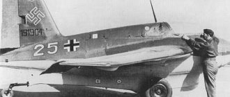
Ta 152 C-0 (military number CI+XM)
Ta 152 H-1 (serial number 110003) in Langenhagen
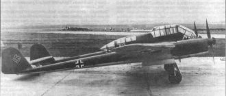
FW 190 V30/U1 (military number GH+KT) was a prototype of the Ta 152 H-0. Photos from three sides
Reinforced armor to protect the Ta 152 from fire from sharp angles
Ta 152 N-10 with a camera installed (project)
Ta 152 with Jumo 222 (project)
Project for installing two MK-103 automatic cannons (synchronized) on Ta 152N and S
Project for installing two Rohrblock 108 blocks under the wing of the Ta-152C and H for launching unguided missiles
Suspension project for Ta-152C and H of five SG 500
Rear fuselage and fin made of wood Ta 152 00-211
Ta 152C and H with wing, in the construction of which steel elements were used
Ta 152 H-1. On the right in the photo you can see the cylindrical insert of the fuselage, on the left the hatch is secured with four clips
Hatch on the cylindrical insert of the fuselage at the front right
Left panel and instrument panel
MG-151 landing gear retraction cylinder and barrel
Jumo-213E propulsion mounting points. Right view
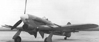
The power plant of the Ta 152 H fighter is a Jumo-213E engine with a three-bladed propeller. Left view
Mounting the engine to the front extended part of the fuselage
Rear top view of the Jumo-213E engine
Fire partition
Left side of the engine hood. Inside view
Right side of the engine hood. Inside view
The upper part of the front extended part of the engine hood. Inside view
Test bench for testing the Ta 152 fuel system
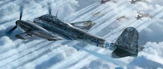
Ta 152 H-1 fighter (serial number 110005) with Jumo-213E engine
Ta 152 C-0, registration CI+XM, with DB-603L engine
Ta-152 V7 (C-0, serial number 110007) with DB-603 engine. This prototype could later be used as a high-altitude aircraft after conversion. The fuselage shape corresponded to the Ta-152N
Ta 152 H-1 (serial number 150167). Rear left view
Ta-152 H-1 (serial number 150167). Front view
Ta-152 H-1 (serial number 150167). Back view
Ta-152 H-1 (serial number 150167) with Jumo-213E powerplant
Ta-152H (drawings to familiarize yourself with the appearance) with the Jumo-213E power plant
Sources:
- Vorläufige Baubeschreibung Nr. 271, Höhenjagdflugzeug Ta 152 H, 13.1.1944 Baubeschreibung Nr. 292, Begleitjäger Ta 152 H, 15.1. 1945 Bewaffnungsübersicht Fw 190 und Ta 152,15.12.1944 Rohrblock 108 Einbau in Flügel mit Behälter, 26.1.1945 SG 500 Einbau in Flügel mit Behälter, 26.1.1945
- Schleppleistungsvergleich verschiedener Kühlersysteme in Ta152H mit Jumo 213 E, Bericht Nr. 03040, February 1944
- Untersuchung der Kraftstoffanlage Ta 152, Bericht Nr. 20 055, 16.9.1944
- Zusammenstellung wichtiger laufender Konstruktionsarbeiten Fw190/Ta 152, 20.3.1945
- Behälteranlage Ta 152 C and H, 1945
- Baureihenübersicht Fw 190/Ta 152, 3.1.1945
- Baureihenübersicht Fw 190/Ta 152, 21.3.1945
- Fw 190 – Ta 152, Einmotorige Jagdflugzeuge, 23. 7.1944
- Erprobungsberichte Ta 152 H in Echterdingen, 1944
- Einbau einer Seitenflosse in Holzbauweise, Zeichn. No. 152.00-211, 1945
source: “Begleitjäger: Tank Ta 152H” // LUFTFAHRT international vol. 5