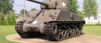
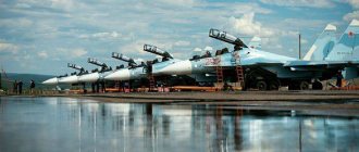
Used T-34 tank: maintenance every day, weak clutch and liters of oil
Brakes and steering
The tank's braking system is combined with a steering system.
The T-34 uses side clutches with automatically operating band brakes for this purpose. They are driven by hand rods, and for lubrication they use constalin, which is used to fill the oilers on the gearbox housing every day. The side clutches of the steel-on-steel system are multi-disk, the thickness of the clutch set is 136-138 mm, and the number of plates ranges from 35 to 43, depending on the thickness and degree of wear. The main problem is thermal warping of the side clutch plates during long turns, and dirt often gets into the system and lubricant leaks through the felt seals. The service life of the mechanisms is relatively short, about 300-1000 kilometers, with daily maintenance, so immediately buy a good supply of lubricant.
The brake itself is implemented using belt mechanisms. The system is controlled in two ways: first, the clutch is released using a lever, and then the band brake is activated. Using the pedal you can brake without disengaging the clutch, which is useful when driving on slopes.
The brake band is steel, but the 13 linings on its surface are cast iron. The parking brake is implemented using a locking mechanism on the pedal drive. The brakes are driven mechanically by rods with a balancing spring. The design is very reliable, but requires constant adjustments and good effort on the pedal.
Suspension
The suspension design of the T-34 is much more complex than that of most cars. It consists of drive wheels at the rear, an idler wheel and five dual road wheels with a diameter of 830 mm and, of course, a track of 36 tracks with a ridge and 36 tracks without a ridge.
T-34. Bojo, wikipedia.org
Drive wheels are mainly of two types: solid cast or with stamped discs, both types with rollers. Occasionally, solid drive wheels without rollers from the 1942 model are found. Tanks produced in 1941-42 can be identified by the presence of a cast wheel with rollers fixed with castle nuts. Tanks produced after 1943 were mainly equipped with a stamped wheel with rollers, the axes of which were fixed with pins. In terms of reliability, all solutions with rollers are approximately equivalent, but the version without rollers lags behind both in terms of noise and efficiency.
T-34 tanks have five rollers on each side. The original design provided for external shock absorption of the rollers - this ensured acceptable noise. But during the production process, the design was optimized to reduce rubber consumption, and in the summer of 1942, STZ installed three central rollers on tanks with no shock absorption at all. Many tanks produced after '42 were equipped with rollers with internal shock absorption.
The sloth, also known as the idler wheel, is located at the front and serves to tension the track. It is usually solid in design.
Guide wheel T-34. wikipedia.org
The Christie-type roller suspension is located inside the body and is one of the weak points of the design. The front roller is heavily overloaded, which causes early destruction of the tires, increased wear of the bearings and the suspension itself. In addition, the springs and shock absorber take up a lot of space inside the body.
The service life of the suspension greatly depends on the surface on which the tank is moving. Operation requires daily checking of all its elements and performing routine repairs as necessary. On average, it coped well even with the mass of T-34-85 tanks, requiring an order of magnitude less attention than the engine and main clutch, which will be discussed below.
Transmission
All tanks are driven by a rear drive wheel and track - unfortunately, there are no all-wheel drive versions. The mechanical part consists of final drives and clutches, a gearbox, and a main clutch. We have already examined side clutches in the chapter “Steering and Braking System”. The final drives here have lateral gears, which are not particularly reliable, but in general their service life is quite acceptable. Depends mainly on the condition of the gearbox outer seal and the oil level.
The final drive is not coaxial
The main problem area of the T-34 tank is the main clutch, in automotive terms this is the clutch. Given the shortage of friction materials, it was made in a steel-on-steel design, and due to the low coefficient of friction of steel friction discs, as many as 21 pieces were required. Due to length restrictions, the working stroke and working gap were very small.
Under conditions of high-quality assembly of prototypes, the clutch was relatively efficient, although the force on the clutch pedal was very high. But during serial assembly, incomplete opening of the discs led to incomplete disengagement of the main clutch, and if the clutch was not fully disengaged, it was difficult to change gears in the box. Especially if this is a T-34 before the July 1942 update.
The T-34 tank went into production with a 4-speed gearbox, made according to a scheme with moving gears - this design was generally accepted at that time. Its main advantages included simplicity and a small number of gear pairs. But at the moment of switching, it required the absence of torque on the shafts. With a “drive” clutch, shifting required a lot of effort, the gear travel was large, and the tooth profile was poorly suited for constant on-off switching.
Twin-shaft gearbox with moving gears according to the Christie scheme
Technological improvements in the form of cutting teeth along the edge one at a time, knurling the side surface of the gear (something like a synchronizer), and processing the shafts to reduce resistance had only a small effect. What worked well with good grip on trucks of that time and was quite acceptable - on tanks of the BT series, on the new and noticeably heavier T-34 did not cope with the task. The forces on the switching mechanism could exceed 50 kg, which complicated the work of the driver and constantly led to the engine going beyond the optimal operating range. And, of course, breakdowns of the gearbox itself were common: the teeth crumbled, and shock loads destroyed the housing and bearings.
The development of a new five-speed transmission began even before the tank went into mass production. It was not just that the tank needed another gear to expand the dynamic range, improve cross-country ability and improve fuel efficiency. The new box used constant mesh gears with clutches, like modern designs.
The introduction of such a box into the series became possible with the supply of new gear cutting machines under Lend-Lease. The fact is that there are almost twice as many gear pairs in the constant mesh gearbox, which significantly increases the load on the machine park. But the introduction of a clutch-based gearbox is the best solution if it is not possible to change the design of the main clutch, which would require altering the connecting dimensions of the power unit and altering the housing. In general, the scope of modernization work would be comparable to creating a new tank with the same engine.
Checkpoint T-34. wikipedia.org
The new gearbox turned out to be demanding on the quality of components; it needed high quality roller bearings. But this problem was solved quickly enough, and the design of the box remained unchanged for many years.
When choosing a tank today, give preference to the T-34 after the summer of ’42 with a 5-speed gearbox or demand a significant discount, since the choice of good contract gearboxes for the T-34 is small.
Motor
The T-34 engine line consists of a single V-2 unit - a diesel V12 with direct injection. This engine was so far ahead of its time that its base is still in use today, and for engines developed in the 30s, it generally looked like an alien from the future.
Judge for yourself: aluminum cylinder blocks, aluminum crankcase, steel wet cylinder liners, aluminum pistons with 5 rings, three compression and two oil scraper rings, 4 valves per cylinder, dry sump lubrication system and oil filters. The operating speed of the engine is 1700-2000 per minute, the volume is 39 liters, and the power is 400-600 horsepower. And all this with a mass of about a ton, which is not bad even in comparison with gasoline engines of the same power.
Diesel engine V-2. wikipedia.org
1 / 2
Diesel engine V-2. wikipedia.org
2 / 2
The secret is simple: the engine was also developed as an aircraft engine, which was a fashionable trend at that time, and it accumulated in its design the developments of several design bureaus over many years. Unfortunately, things weren't looking good in terms of reliability and cost. In August 1940, the design bureau of the Stalingrad Motor Plant, in its memorandum to the Central Committee of the All-Union Communist Party of Bolsheviks, described its design as follows: the main disadvantages of the plant representatives included the fact that the B-2 “is an unfinished example of an aviation diesel[,] <…> which is neither reliable, nor very compact and powerful enough, nor any cheap engine.” And this was the harsh truth.
The development of the engine took almost ten years, and only during the war was its service life brought to acceptable levels. By the time mass production of the T-34 tank began, the warranty life was 100 engine hours for the T-34 and 80 engine hours for the KV-1, and only at the insistence of People’s Commissar M.A. Malyshev, these figures were increased to 150 and 100 engine hours, respectively, with the 300 desired by the military. The actual MTBF was often lower than the warranty figures. Only engines manufactured in 1944 were able to exceed the MTBF of 250 hours with a margin, some of them could work for more than 1000.
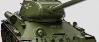
T-34-85
Do not compare operating modes with aviation or automobile ones; in tanks, the operating time at maximum power mode is more than 30% of the time, which is six times longer than that of automobile engines, and more than 55% of the time it spends at a load of more than 60%. There is also a lot of dust in the intake, and in the summer overheating is added due to the high air temperature.
The main weak point of the engine is not the fuel equipment at all, and there were no special problems with a cold start. Although refueling had to be treated with respect: filter diesel fuel through silk fabric, avoid significant admixture of kerosene, heat the fuel before starting in cold weather, just like the engine itself. However, the pneumatic starter with a good power reserve made it possible to start a serviceable engine even in severe frosts, since the oil was poured into the tank hot from the heating station. A mixture of 45% water and 55% ethylene glycol was poured into the cooling system in winter. Alcohol-glycerin mixtures with a nomenclature down to -32 degrees were also allowed.
The main problem throughout the forties was wear of the cylinder-piston group, burnout of the pistons due to overheating, breakthrough of the gas junction of the cylinder head and liner, as well as disruptions in the fuel supply and operation of the lubrication system due to breakdowns of oil pumps. Oil consumption in a worn-out engine was literally in liters, reaching 5 kilograms per hour. Traditionally, the report from the Aberdeen Proving Ground is cited as the main document on the condition of the engine at the beginning of 1942. Yes, the T-34 tank was tested in the USA and studied there in great detail.
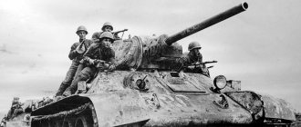
T-34-85, captured by the US Army in the Korean War. wikipedia.org
The main problem of the Soviet 39-liter V12, according to overseas experts, was the low quality of air purification. The centrifugal oil air cleaner lost oil, did not clean it, sent oil to the combustion chambers, which led to peddling and water hammer. The second problem was the weakness of the cooling system - it did not allow it to operate at maximum power for a long time, even in winter conditions. However, judging by the report, the Americans did not fill the Pomon type filter with oil, as a result of which the filter actually did not work. The service life of the engine on the tested tank was 73 hours.
The air filters clearly needed improvement anyway. By the end of 1943, tanks were already using filters of the “Cyclone” design, and after 44, “Multicyclone” filters, which provided an order of magnitude better air filtration and less labor intensive maintenance.
The copper cylinder head gaskets could not withstand operation at maximum power. Later, the processing accuracy of the blocks was improved and a solid aluminum gasket was used, and then a “metal package” gasket was used to ensure the operation of the gas joint.
T-34-85 with additional armor, 1996, Bosnia. wikipedia.org
Oil pumps were consistently improved, drive shafts, working pairs and clearances were changed. By 1945, the main problems had been solved. Surprisingly, the rest of the motor design turned out to be very successful. Of course, it is extremely labor-intensive to maintain and expensive, but nonetheless resourceful.
Post-war modifications of this engine for railway and automotive vehicles were significantly improved, and their service life was increased to more than 10 thousand hours on heavy trucks and tracked vehicles. When purchasing a T-34 tank, you can now count on installing a contract unit or repairing the original engine using new technologies, which will allow you to operate the equipment relatively reliably.
To take or not to take?
As you can see, the T-34 is a rather complex design that cannot be called indestructible in any case - on the contrary, even maintaining a serviceable tank in working condition requires a lot of effort and money. And all jokes aside, there are enthusiasts who move from fantasizing about their own tank to action. We know of at least two projects in recent years that are easy to Google.
Survey
Would you take a used T-34?
Your voice
Total votes:
TRACK MOTOR
The purpose of the tracked propulsion unit is to provide forward motion to the tank due to the torque supplied from the engine to the drive wheels.
Caterpillar propulsion device
The track drive consists of two track chains (caterpillars), two drive wheels, two idler wheels with a tensioning mechanism, twelve lower support rollers and six upper support rollers.
TRACK CHAIN (TRACK)
Each caterpillar is a fine-link chain consisting of 87-90 individual track links connected to each other by pins that are inserted into the track eyes.
Track 1 (Fig. 83) is a shaped steel stamping, which has two rectangular windows for engagement with the teeth of the drive wheel and a ridge for guiding the rollers rolling along the track and for protecting the tracks from falling off the drive and guide wheels.
The track pin 2 has a head at one end, which keeps it from longitudinal displacement in one direction, and at the other, a groove into which a spring ring 3 is installed, which keeps the pin from axial displacement in the other direction. A washer 4 is installed between the track and the spring ring,
Rice. 83. Caterpillar track: 1 - track; 2 - finger; 3 - spring ring; 4 - washer
Rice. 84. Drive wheel (section): 1 - bracket; 2 - hub; 3 - ball bearings; 4 — spacer sleeve; 5 — oil seal ring; 6 — oil seal; 7 - nut; 8 — lock washer; 9 — locking ring; 10 — hairpin; 11 - drive shaft; 12 — cap; 13 - bolt; 14 — rubber gasket; 15 - bolt; 10 — ring gear; 17 - holes for lubrication.