Mikoyan-Gurevich "MiG-1 / MiG-3", Fighter
Mikoyan-Gurevich MiG-1 and MiG-3
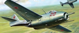
The first joint work of Artem Mikoyan and Mikhail Gurevich, who later became one of the most famous aircraft designers, took place in 1938. The design bureau formed as a result of this cooperation is still known today by the initials of its creators - MiG. The first development began with an Air Force competition to create a new interceptor fighter, which was to be equipped with a 12-cylinder V-engine designed by Mikulin. Almost simultaneously, two options were developed. The first of these was an aircraft designated Type 65, but it was immediately rejected in favor of a design by the Ilyushin design bureau. The second version of the Mikoyan-Gurevich MiG-1 (originally designated I-61 and equipped with AM-35A and AM-37 engines) won the competition, which was followed by an order for three prototypes under the designation I-200. The first of them took off on April 5, 1940. After flight tests, serial production of MiG-1 aircraft began, reaching speeds of up to 628 km/h (390 mph). In this regard, in 1940-41. The USSR claimed that the MiG-1 was the world's fastest fighter-interceptor. However, the aircraft had a number of shortcomings, so only about 100 aircraft of this type were built. It was hampered by insufficient stability, short flight range, and low structural survivability. As a result, a new modification of the fighter appeared - the MiG-3, which had improved aerodynamics and an increased angle of the transverse V of the outer wing sections. In addition, the fuel supply, weapon power and armor thickness were increased. A total of 3,422 aircraft were built (including MiG-1 type aircraft). As a result of attempts to modify the MiG-3, the I-210, also known as the MiG-3-82, with the M-82 radial engine designed by Shvetsov, an improved version of the I-211, as well as the MiG-ZU with the AM-35A engine designed by Mikulin appeared. However, none of the listed options went into mass production.
| modification | MiG-3 |
| Wingspan, m | 10.20 |
| Length, m | 8.25 |
| Height, m | 3.50 |
| Wing area, m2 | 17.44 |
| Weight, kg | |
| empty plane | 2699 |
| takeoff | 3350 |
| fuel | 463 |
| engine's type | 1 PD AM-35A |
| Power, hp | |
| nominal | 1 x 1200 |
| takeoff | 1 x 1350 |
| Maximum speed, km/h | |
| near the ground | 505 |
| on high | 640 |
| Practical range, km | 1250 |
| Rate of climb, m/min | 877 |
| Practical ceiling, m | 12000 |
| Crew, people | 1 |
| Weapons: | one 12.7 mm UBS machine gun, two 7.62 mm ShKAS machine guns; 6 NURS 57-mm RS-82 or 2x 100 kg FAB-100 or FAB-50 bombs |
Carrier-based fighter MiG-23K
In 1976, the MiG-23K carrier-based fighters (“K” - shipborne; product “23-32”) were adopted into service with the USSR Navy. Initially, the MiG-23K was supposed to become fighter-bombers, perform the functions of fighters, interceptors, attack bombers, reconnaissance aircraft and electronic warfare aircraft and be part of the air groups of Project 1143 aircraft carriers (Minsk) being built in Leningrad and Komsomolsk-on-Amur.
However, plans soon changed; It was decided to assign strike missions and electronic warfare and electronic warfare tasks to the Su-17M3K attack-bombers - a spoiled version of the Su-17M3 fighter-bomber, and to entrust reconnaissance to carrier-based aircraft DLRO Yak-44.
Pilot and technical personnel against the backdrop of a deck-based attack aircraft-bomber Su-17M3K
Pilot in the cockpit of a Su-17M3K
Carrier-based attack aircraft Su-17M3K
Deck-borne aircraft DLRO Yak-44E on the deck of the aircraft carrier "Minsk"
Layout of the Yak-44E carrier-based AWACS aircraft
When developing the MiG-23K, the MiG-23ML fighter was taken as a basis, from which the naval version differed in the nose of the fuselage lowered 2° down to improve visibility from the cockpit, a reinforced landing gear, and the installation of a landing hook (the rotating ventral ridge was replaced by two ridges) , increased area and height of the keel. In addition, the “23-32” received a wing with double-slot flaps of increased area and an in-flight refueling system.
Other differences in the design of the deck vehicle were:
- • folding wing consoles;
- • reinforced landing gear;
- • introduction of an improved system for creating additional lift on the PGO equipped with double-slot flaps;
- • two additional ventral hardpoints (in front of the main landing gear).
Diagram of the MiG-23K carrier-based fighter
The avionics composition of the MiG-23ML fighter was taken as the basis for the on-board equipment of the MiG-23K; The differences were in the installation:
- • automatic control systems SAU-23MLK;
- • navigation system “Polet-2K-23”;
- • Sapphire-23ML-K radar (later replaced by Sapphire-23MLA-K);
- • radio station R-862;
- • heat direction finder TP-26;
- • limit signal systems SOS-3-4;
- • equipment for automatically guiding the aircraft to the target according to commands from the automated guidance system installed on the Yak-44.
Carrier-based fighter MiG-23K
In 1982, for third world countries that had aircraft carriers, the MiG-23KE carrier-based fighter (“E” - export) was developed, which was distinguished by a simplified avionics composition and improved strike capabilities. OKB im. Mikoyan focused on India and the countries of Latin America: primarily on Argentina, where a civilian government came to power, and (in the future) on Brazil, whose dictatorial regime was gradually losing ground.
Home » Mig-3 - “Black Sea” camouflage (ModelArt)
| Mig-3 - “Black Sea” camouflage (publisher: ModelArt, author: E.Zarkov, 1:32, repainted by me) |
The ModelArt version of the MiG-3 represents the fighter that fought in the Crimea in 1942, and I built it in tandem with the Bf.190F-4, which was an opponent of Soviet fighters in the battles for the Crimea in 1941-1942.
I chose the “Black Sea” camouflage found on one of the well-known sites (“VVS research page”):
This is “an aircraft of the 62nd IAP of the Black Sea Fleet Air Force” according to Massimo Tessitori.
I recolored the original PDF directly in Illustrator, using the simplest (but not the worst) means - color replacement and color spots. I evened out transient spots by climbing across the screen with a specially printed cardboard ruler.
I changed all the colors: blue, and steel (insides), and the color of the pipes. I mainly chose colors from AKAN catalogs - their color tables are considered the most reliable. The colors are (RGB):
green - #546214 (AMT-4 Green/protective) exhaust - #433737 ("Burn Metal") blue - #b6dee8 (AMT-7 Blue) red - #ED1C24 (left as in the original) internals - #949a9b (A -14 Grey/Steel)
and also selected to my own taste:
black (camouflage spots and hood) - #2D2D23 intermediate (transition from black to green) - #414B23
The model is built according to the same scheme as the previous one, with some changes:
— the patterns are printed on the same glossy photo paper Lomond Glossy Inkjet Photo Paper 160 g/m2, but after printing the sheets are immediately coated with a couple of layers of Motip Clear Vanish acrylic varnish. The coating dramatically improves the mechanical strength of the surface and dramatically reduces the absorbency of the photolayer: random drops of coffee can now simply be wiped off. The varnish also theoretically protects against ultraviolet radiation. The glossiness of the surface of the photo paper does not change in any way: the same pleasant, even glow;
— this time I started building not from small things, as the instructions recommend, but right from the cockpit;
- for glazing, a thinner polyester film was used - 0.05 mm (torn from an unnecessary photo album);
— to touch up edges/defects, use appropriate acrylic paints based on white acrylic enamel with the addition of the necessary tinting pastes.
The fully assembled fuselage looked like this:
The stitching on black, as one might expect, is not very visible, and is not visible at all in the photo. However, there are already enough details on the hood, and the appearance has not become poorer.
The corresponding part of the propeller spinner is painted with the matte black paint mentioned in my previous assembly description. The propeller blades will be the same (as expected).
I like what I get so far.
Wings – frame replenished
I glued and installed the wings.
To prevent sagging of the skin, the wing frame was replenished with additional pairs of ribs in the consoles. Additional ribs were obtained by scaling the ribs 39/40 with the corresponding height adjustment in place (wing profile of variable height). In addition, I had to tinker with installing the landing gear niches. For precise installation in place, the front ends of the ribs 39/40 had to be moved to the sides.
The strips forming the rear/end edges were, as usual, cut out from the same paper (160 g/m2) and glued to the bottom skin, along the rear edge - 2 overlapping strips.
Proper paper thickenings are glued under the upper ends of the landing gear legs.
Having glued the skin on top, I came to the conclusion that instead of additional ribs it would be better to add spars to the console - the photographic paper borrowed from my son turned out to be a bit soft, and the wings turned out uneven. In the previous model (P-40N) the extra ribs were useful, but the paper was stiffer. The spars would be better in this model, and in general - this is exactly what is done in many models. A good thought comes later.
I glued the wings and glued the fairings:
I placed the wings exactly according to the marks on the fuselage, and glued the fairings (their rear and central parts) exactly along the wing and fuselage. The front ends, as usual, turned out to be longer than necessary - this is a well-known glitch of this model. I cut it in place. By the way, I didn’t cut the fairings - with due care it is possible to install them without this.
Chassis - fresh (?) thought
While building the chassis in my spare time, a fresh idea came to my mind, which, apparently, had never occurred to anyone before (judging by the photographs available to me).
If you look closely at the drawings, you can see that the main landing gear struts are recessed into the doors, for which purpose the doors have corresponding bulges, which are given in the model as separate parts 64b/65b. At the same time, the instructions and patterns avoid this circumstance and suggest simply attaching the sashes to the racks. Which is what everyone usually does (including me in the first “release”). The look is somewhat unreal and as if disheveled.
The problem is solved simply: holes are cut in the sashes with an indentation of 1.5 mm from the line indicating the place where the convex 64b (65b) is glued. Next, the bulges are glued into place, and the resulting indentations are painted over with gray to match, if desired (or you don’t have to paint them - it won’t be visible anyway). Next, the sashes are glued to the posts with the required slope - so that the lower edges of the sashes are 1.5 mm away from the planes of the wheels. It turns out well and is easy to glue: the lower cut of the “winding” of the stand just rests against the edge of the cutout, and the lower end of the stand is recessed into the recess exactly as much as the wire coming out of the lower cut of the “winding” allows.
By the way, I cut off the folds (“petals”) on the sashes - they are not in the drawings, and it will be enough to fix the upper edges of the sashes with a drop of glue. The wheels are fixed with washers on the paint and rotate. To prevent the ends of the axles and the washers from sticking out on them, recesses were drilled in the middle of the wheels on one side with an F6 drill, and when gluing the disks, the discs were pressed into them with the oval rear end of the marker.
The model is ready and photographed
Having glued all the remaining parts (the chassis was placed according to the template, as in the previous release, the antenna was made of wire, the pitot tube was made from a syringe needle, etc.), I began to take photographs. This is what happened:
And another collage - for comparison: the model and the original drawing (though different sides - the camouflage patterns are slightly different, as drawn by Tessitori).
Basically similar (with an exception for distortion when shooting at close range - due to light). That's what was required.
It can be seen, by the way, that Zarkov’s antenna mast is noticeably larger than necessary - I only noticed this in this collage. I checked the drawings and it’s true, the mast is too big.
09/27/2007
Update from 01/07/2010
This repainted model is offered by Moshe Lemer along with other models by E. Zarkov:
https://www.papermodels.co.il/Store.htm
For this edition I slightly changed and improved the patterns:
First of all, I changed the colors - brought them to the modern idea of \u200b\u200bcoloring of those times. In addition, I added three-dimensionality in some significant places so that there was at least the illusion of separation of the moving surfaces.
Update dated July 20, 2011
The recolor that I gave to Moshe Lemer was published by the Moscow Toy Factory:
