Project evaluation[edit | edit code]
The Project 206MR RSA can be compared to some extent with the US Navy's Pegasus RSA and the Italian Navy's Sparviero RSA. If the Project 206MR RKA was inferior to the first in all characteristics, then it was superior to the second in artillery and anti-aircraft weapons, inferior in anti-aircraft missile defense capabilities and speed.
According to many experts, the modernized project 2066 was optimal in size, performance and armament, since it involved fighting enemy ships with a displacement of up to 3000 tons. However, the leadership of the USSR Navy continued to believe that the RKA should hit large combat missiles with its anti-ship missiles enemy ships. This task, as shown by the local wars of the late 80s and early 90s, was practically impossible to solve.
Domestic anti-ship missiles. Missile boats enter the battle. Part 1.
After the development of the Strela and KSShch missile systems for cruisers and destroyers began in accordance with the resolutions of the Council of Ministers of December 30, 1954, the question arose about deploying missiles on boats as well. As carriers of such weapons, they even had some advantage over large ships. Due to its small size, the boat was detected by radar equipment of those years at a distance half as great as that at which the boat's radar detected an enemy cruiser. In terms of cost, the boat was 40 times cheaper than a destroyer and 200 times cheaper than a cruiser. In addition, it was possible to build boats on a mass scale without expanding the existing shipbuilding base.
The resolution of the Council of Ministers of August 18, 1955 specified the arming of torpedo boats with projectile aircraft, namely, the creation of the first boat-based missile system with a range of 25 km.
The choice of Moscow KB-1 as the developer of the complex as a whole and most of the onboard and shipborne equipment of control and guidance systems (except for the autopilot, which was developed at OKB-923) was determined by the vast experience of this organization, which had already created the Kometa anti-ship complex, anti-aircraft missile the Berkut S-25 system and leading at that time the design of the K-5, K-10 and K-20 aviation complexes, the coastal and ship-based complex with the Strela missile, as well as the S-75 air defense system. KB-1 in the mid-1950s. was almost a monopolist in the field of creating complexes with guided cruise and anti-aircraft missiles.
When determining the technical appearance of the complex, it was taken into account that, along with the above advantages, the boat as a carrier of missile weapons also had a number of disadvantages, primarily limited capabilities for deploying missiles and related equipment. In relation to boats, it was absolutely impossible to create stabilized launchers adopted for the Strela and KSShch missiles. Instead of stabilizing the rocket, during pre-launch preparation it was necessary to enter into the on-board equipment data on the angles of roll and pitch of the boat. In contrast to the operating conditions on large ships, on board the boat the missile and the ship's equipment of the complex were exposed to much more powerful vibrations, repeated shocks and overloads characteristic of the high-speed sailing of the “mosquito fleet” in rough seas. And the sea itself was only one meter away from the missile launcher, which led to intense splashing and flooding.
The small height of the boat, along with a positive property - low radar signature, also caused a significant drawback. The boat's radar equipment at maximum range could detect radiation reflected only from the masts and superstructures of a large enemy ship. Even this weak signal allowed an experienced operator to detect a target, but it was clearly insufficient to lock on with a semi-active homing head made at the level of technology of the mid-1950s. Therefore, of the radar equipment for the missile, the active homing head was most suitable. Taking into account the capabilities of the elemental base of the equipment, which, in terms of weight and size parameters, is acceptable for use on board a missile, auto-tracking of even such a large target as a cruiser was ensured at a distance of no more than 10-15 km from it, i.e. on the final leg of the flight.
Thus, when choosing a control system, we proceeded from the use of an active homing system only at the final section of the trajectory. But she could not provide control during the previous phases of the flight. Based on the relatively short flight range of a boat missile, limited by the capabilities of the boat's radar search equipment, it turned out to be permissible to use an autonomous system with an autopilot, without radio correction from the ship's equipment. Even a high-speed target could travel no more than 1 km during the autonomous flight phase of the rocket.
The basis of the missile’s onboard equipment was the MS-2 homing head, created at KB-1 by a team of designers headed by Yakov Ivanovich Pavlov. According to Jane's handbook, it operated on one of four fixed frequencies in the 8-10 GHz range.
Post-launch control of the rocket was carried out by the AP-15 autopilot. The flight altitude was determined according to the pressure altimeter (statoscope) and was maintained constant - 300 m. When the missile reached the set value of the range traveled, the homing head turned on the radiation and, scanning in the horizontal plane, began searching for a target at a given distance with a tolerance of ±1 km. After receiving eight response impulses, she switched control of the rocket to herself. The length of the subsequent homing section ranged from 5 to 12 km.
The use of missiles was ensured by the shipborne equipment of the complex, primarily developed at NII-49 (currently the Granit Central Research Institute) by a team of designers led by Viktor Andreevich Kucherov, the Rangout radar,
operating, according to the Jane reference book, in the range of 8-12 GHz at four fixed frequencies, spaced within a range of ±10 MHz wide. The Rangout station had two power levels (20 and 100 W) and could provide all-round visibility with a frequency of 4 or 12 rpm. Based on basic geometric calculations, when placing the radar antenna on the mast of a boat approximately 10 m from the water surface, the superstructure of an enemy ship with a height of 20-30 m could be detected at a distance of 25-28 km. With normal refractive indexes, the detection range should have increased to 30-35 km. However, the radar developers were in for a pleasant surprise: that very rare case when the system’s performance not only does not deteriorate, but even increases during testing. During experimental work, it turned out that when a radar of this frequency range operates with an antenna located at a low altitude, a kind of radiation propagation channel is formed along the water surface at a distance much greater than the distance of the geometric horizon. Under favorable conditions, a large target was detected at a range of up to 60 nautical miles (112 km). As a rule, the cruiser pr. 68bis was detected by the boat radar at a distance of 60-80 km. In turn, the missile boat was detected by the cruiser's radar at a range of 20-30 km. Nevertheless, the guaranteed detection of a destroyer by a boat radar at a distance of 24 km was considered satisfactory. The PMK-453 sight was used as a backup optical aiming device.
P-15 cruise missile in pre-launch configuration.
Diagram of the P-15 cruise missile.
After detecting the target, the ship’s fire control device “Klen” was connected,
developed under the leadership of chief designer Alexey Alekseevich Moshkov at the Marine Research Institute-1.
To develop the flight mission issued on board the missile, along with data on the coordinates, speed and course of the target entering the Klen equipment from the Rangout radar, the values of the shooting boat’s own speed and course, and the current parameters of pitch and roll were entered into it. During pre-launch preparation, the boat had to maintain a constant course at a speed of at least 15 knots for several minutes, with an accuracy of ±10-15°, coinciding with the direction to the missile’s meeting point with the target.
On the contrary, for the development of the P-15
(designation in correspondence -
“product 4K-40”)
they chose a newcomer - a branch of OKB-155A.I. Mikoyan. This was the first independent work of the team headed by A.Ya. Bereznyak. Alexander Yakovlevich Bereznyak, born in 1912, worked in the aviation industry from the age of 19. After graduating from the Moscow Aviation Institute in 1938, he entered the V.F. Design Bureau. Bolkhovitinov, where in 1941-1942. Together with AM Isaev, he created the first Soviet rocket aircraft, BI. This stage of Bereznyak’s life and work dates back to the 1950s. was widely promoted in the interests of establishing domestic priority in the field of rocketry and jet aviation, although the BI interceptor itself could not be brought into serial production and adoption. On the contrary, in pre-perestroika times, the further life path of Alexander Yakovlevich was lost in the fog, as it was associated with ideologically dubious or too secret circumstances. At the end of the 1940s. Bereznyak became deputy chief designer of OKB-2 plant No. 1, located in the village of Ivankovo (Podberezye post office) on the Volga, opposite Dubna. The plant was built in the late 1930s. on the shores of the newly filled Moscow Sea and was originally intended for the production of seaplanes. The chief designer of OKB-2 of Plant No. 1 was Heinz Ressing, a German brought from defeated Germany, as, indeed, were the majority of the engineering staff of this design bureau. It can be assumed that Alexander Yakovlevich played the same role in this Aryan team as the second secretary of the Central Committee of the Communist Party of the Union Republic in the structure of the CPSU, who was Russian by nationality.
By the early 1950s. It became clear that the work of OKB-2 to create an experimental “aircraft 356” turned out to be as futile as the work of other “captured” scientists and designers. The main reason for this was the isolation of design bureau data from other organizations in the defense industries of Soviet industry. They did not want to share the latest achievements in what were considered particularly secret areas of science and technology with people who, at least theoretically, were destined to return to the West sooner or later.
By decree of the Council of Ministers of September 1, 1951, Plant No. 1 was involved in serial production of the first Soviet anti-ship missile KS, developed by the OKB-155 team headed by A.I. Mikoyan. Nine days later, by order of the Minister of Aviation Industry, a branch of OKB-155 was organized at the plant to provide technological support for the production of KS. After the liquidation of the German OKB, the OKB-155 branch was headed by A.Ya. Bereznyak. Gradually, the OKB-155 branch moved from solving purely production problems to fine-tuning and ensuring testing of the K-10S, Strela, KS-7 and X-20 cruise missiles. All of them were designed at OKB-155, where work on missiles was headed by M.I. Gurevich. The latest rocket development of the Mikoyan Design Bureau - the Kh-22 aircraft rocket - was completed by Bereznyak's team, which in July 1965 became an independent OKB-2-155, and from April 1966 received the open name MKB "Raduga".
Of course, long before the government decree was issued, the technical appearance of the rocket was determined in general terms based on the results of preliminary studies.
All anti-ship missiles previously created in the USSR were equipped with air-breathing engines. The “Komet” that was put into service and the KSSH was being tested had RD-500 and RD-9 turbojet engines, which were also used on fighters, and the “Storm” coastal missile, which was only brought to the stage of flight testing, had a ramjet RD-1A. However, the turbojet engine must be turned on and brought into operation before the launch of the rocket, which was appropriate on board a cruiser in preparation for the launch of the ship's modification of the Comet - the KSS missile, or on a destroyer preparing to launch the Pike. But for a wooden boat with dimensions not much larger than the dimensions of a rocket, any lengthy so-called “pre-launch race” of the engine obviously threatened with disastrous consequences. On the contrary, it was in principle impossible to start a ramjet engine before the rocket took off and accelerated to a speed of at least half the speed of sound. As the experience of creating the “Storm” has shown, for this the rocket had to be equipped with a much more powerful launch-acceleration engine instead of a conventional launcher, which would lead to an increase in size and weight beyond acceptable values.
In addition, with a given relatively short range, the advantages of air-breathing engines, which use atmospheric oxygen and, therefore, do not require the placement of an oxidizer on board the rocket, did not have time to fully manifest themselves. Thus, a rocket engine launched at any speed was quite suitable for the new rocket.
In the mid-1950s. The solid fuels developed in the USSR burned stably only at high pressures. This determined their high burning rate. Almost all domestic solid fuel engines operated for no more than a few seconds, which was tens of times less than the required flight duration of a cruise missile. In addition, these engines were still very heavy and had low energy.
By this time, liquid rocket engines with a thrust level close to that required for a boat rocket had already been used in anti-aircraft and aviation missiles in the USSR. Of course, the operating conditions of the P-15 excluded the use of cryogenic liquid oxygen, which was used in the first ballistic missiles, providing the greatest energy. Of the high-boiling components, the most developed by that time were nitric acid in combination with kerosene or triethylamine xylidine (“fine”, also called TG-02). The latter self-ignited upon contact with nitric acid, which ensured reliable starting and stable operation of the engine.
The greatest experience in creating engines using high-boiling fuel components at that time was accumulated by the team of OKB-2, part of NII-88, led by Alexei Mikhailovich Isaev, Bereznyak’s colleague in the development of the BI missile interceptor.
The fuel supply system was not immediately selected. At the beginning of development, the C2.278 engine with displacement fuel supply was considered. A similar scheme was used on the first domestic anti-aircraft missiles of the S-25 complex, in the operational-tactical ballistic missile R-11 (8A61), the first in the family of the famous Scuds. But on these products, the tanks formed the power body of the rocket, which was supposed to provide sufficient strength and rigidity to withstand external loads. Therefore, their additional strengthening, due to the influence of the high (several tens of atmospheres) internal pressure in the tanks required for displacement supply, did not greatly affect the level of weight perfection of the rocket design. However, Bereznyak adopted a design with inserted tanks for his rocket. This was influenced by both aircraft-building traditions and the fear of what, since the time of Peter I, was called in the navy “an inevitable accident at sea.” It was assumed that in an emergency, the extra wall of the outer power housing covering the tanks with self-igniting components would not be damaged. After all, even a simple spill of acid from a damaged tank onto the deck of a boat would have much more serious consequences than on the territory of an anti-aircraft missile unit. But the insert tanks became heavier almost in direct proportion to the pressure and, as it increased, they became a load too heavy for the rocket to lift. Therefore, we had to abandon displacement feed, despite all its advantages in terms of simplicity, low cost and reliability.
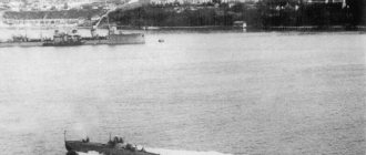
Boat pr. 183E TKA-14, on which the P-15 missiles were tested.
Ultimately, the missile entered service with the S2.722V engine equipped with a turbopump unit.
Since the launcher gave the rocket a speed not exceeding 100 m/s, further acceleration had to be provided by a liquid-propellant rocket engine, which, when operating at high speed, would develop a thrust of 1211 kg. Upon reaching a speed of about 1150 km/h, the thrust decreased to a value of 511 kg, approximately equal to the aerodynamic drag force during the cruising phase of the flight.
Based on the experience of previous developments and moderate requirements for maneuverability, an “aircraft” aerodynamic design was adopted for the P-15. However, in contrast to the previously created and developed aviation “projectile aircraft” (KS, K-10S, X-20), the P-15 was equipped with a so-called “diamond-shaped” rather than swept wing. This was determined by extremely strict restrictions on the transverse dimensions. The width of the boat was almost equal to the sweep of the swept wing of the KS rocket. On the boat, it was necessary to place two launchers on board, despite the fact that there was also a control room between them. “Diamond-shaped” wings have already been used on anti-aircraft missiles of the S-25 complex, mass-produced since 1953. Currently, such wings are classified as trapezoidal, although they are very reminiscent of triangular ones, differing from them in the thoroughly cut off tip and forward swept trailing edge. The keel and stabilizer had the same planform. The consoles of the latter were located at an angle of 30° to the horizon, helping to ensure not only longitudinal, but also directional stability. The designers considered it inappropriate to increase the height of the fin - this led to an increase in the dimensions of the launcher, and the use of the ventral fin was hampered by the starting engine. The layout turned out to be promising: three identical tail surfaces evenly spaced around the circumference subsequently fit perfectly into the newly created container launcher. The controls were located according to the usual aircraft layout - ailerons on the wing, rudders on the fin and stabilizer.
Initially, the rockets were equipped with wings of a riveted design traditional for aviation. Subsequently, the technologists of the Dubninsk plant developed a much more productive process for manufacturing a solid-cast wing using the squeezing method. The new wing design was put into production at the serial plant in Arsenyev. The designers and technologists were awarded the VDNKh medal.
In the front part of the fuselage, under a radio-transparent fairing made of ACT fiberglass with PS polystyrene, there was an antenna developed in KB-1 under the leadership of Ivan Prokofievich Kucherenko for a homing head (GOS), the main equipment of which was located in the next fuselage compartment. Next, a 4G-15 high-explosive cumulative warhead, a compressed air balloon, an aluminum alloy fuel tank, the main units of autopilot equipment, and a spherical oxidizer tank made of aluminum-magnesium alloy were located in sequence. Compressed air was used to operate pneumatic steering gears, as well as in the system for displacing fuel components from tanks.
Created under the leadership of chief designer Ivan Ivanovich Kartukov at OKB-2 of Plant No. 81, the SPRD-30 starting engine was made according to the usual design for those years with an inserted charge of ballistic solid fuel weighing 149 kg, placed in a steel combustion chamber. The total weight of the launch vehicle was 480 kg. The nozzle was inclined downward relative to the longitudinal axis of the engine so that the thrust vector passed near the center of mass of the rocket, which ensured the minimization of the disturbing moment caused by the operation of the starting engine. The same purpose of reducing disturbances acting during the operation of the starting engine was also served by mounting the accelerator on one front and two rear adjustable units. The separation of the starter occurred at the end of the work under the influence of weight and speed pressure. The engine thrust was in the range of 28-30 tons, the operating time was about 1.5 s.
Project 183R
The development of the boat for the P-15 missile was entrusted to the Leningrad TsKB-5. It was located at the Leningrad plant, founded in 1933 as a shipyard of the OGPU Marine Border Guard, and in 1939 transformed into Plant No. 5 of the NKVD. During the war, the Navy became the main customer, and the plant was transferred to the People's Commissariat of Shipbuilding. In the first post-war years, OKB-5, the so-called “sharashka”, was organized on the territory of the plant, which employed mainly a “special contingent” - a group of prisoner engineers led by Pavel Gustavich Goykins, transferred from a similar organization in Kazan - OKB-340. They developed the largest of the post-war torpedo boats, Project 183, which was put into service in 1949. The boat, Project 183, was created using the experience of building Soviet and foreign torpedo boats (Elko, Higgins, Vosper), arrived under Lend-Lease and were going to the USSR.
Design[edit | edit code]
Hull and superstructure[edit | edit code]
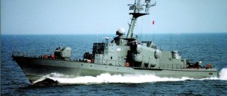
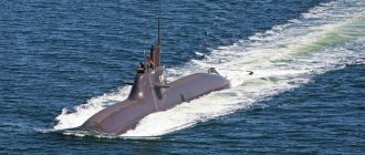
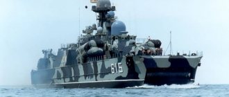
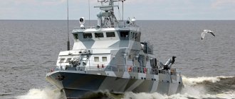
The ship has a smooth-deck steel hull with a slightly submerged bow wing and round chine contours in the bow and a controlled transom plate with sharp chine contours in the aft section. On the deck there is an extended superstructure made of lightweight AMG alloy with a conning tower and an open navigation bridge in the bow. To improve flushing conditions during radioactive contamination, the junction of the deck with the side and the upper part of the superstructure were rounded. The boats could use their entire arsenal of weapons in waves up to 5 points at speeds up to 35 knots and at 4 points without restrictions. Unsinkability was ensured by dividing the hull into 10 compartments by waterproof bulkheads. The boat remained afloat when any two adjacent compartments were flooded. The superstructures are made of light alloys. The weapon can be used at speeds up to 35 knots and sea waves up to 5 points.
Power plant[edit | edit code]
The power plant is mechanical, three-shaft with three M-504 diesel engines of 5000 liters each. With. each with reverse gearboxes, which provided forward, reverse and idle speed with constant rotation of the crankshaft and transmitted rotation to three three-bladed fixed-pitch propellers. Diesels are equipped with an automatic alarm and protection system. The assigned engine life before the first overhaul is 2,500 hours, and the full life is 10,000 hours at a speed of 2,000 rpm.
The AC electrical power system included 1 diesel generator DG-200 with a power of 200 kW and 1 diesel generator DG-100 with a power of 100 kW, located one each in two engine rooms.
Project representatives[edit | edit code]
Project 206MR and 2066 missile boats[edit | edit code]
| Name | Serial number | Commissioning | Service | Write-off | State |
| "R-27" | 241 | 31.12.1977 | , KFL | 10.04.2002 | Recycled. |
| "R-44" | 242 | 30.09.1978 | , | 05.10.2008 | Since 2001 - “Corsair”. In 1984-85 modernized according to project 2066. Disposed of. |
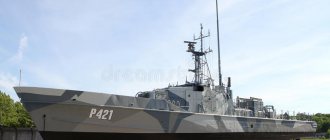
| "R-50" | 243 | 30.12.1978 | , KFL | 2014 | From 08/15/2004 - “Karachay-Cherkessia”. Decommissioned. Opened on August 29, 2015 as the Pokrovsky Watchdog Museum in Engels. |
| "R-221" | 244 | 30.12.1978 | 16.03.1998 | Recycled. | |
| "R-254" | 245 | 10.01.1979 | 05.07.1994 | Recycled. | |
| "R-260" | 246 | 21.12.1979 | , Ukrainian Navy | 30.11.2004 | From 01/10/1996 - “Uman”. Recycled. |
| "R-262" | 247 | 12.12.1980 | , Ukrainian Navy | From 01/10/1996 - “Pryluki”. As part of the Ukrainian Navy, the Termit anti-ship missiles were dismantled in December 2018. | |
| "R-265" | 248 | 15.11.1980 | , Ukrainian Navy | 07.11.2012 | From January 10, 1996 - Kakhovka. Recycled. |
| "R-251" | 249 | 15.06.1981 | , Ukrainian Navy | 30.06.2001 | From 01/10/1996 - “Tsyurupinsk”. Recycled. |
| "R-15" | 250 | 29.10.1981 | , Ukrainian Navy, Georgian Navy | 13.08.2008 | From 01/10/1996 - “Konotop”, from 06/30/1999 - “Tbilisi”. Sunk by the Russian Armed Forces in Poti during the 2008 war. Recycled. |
| "R-25" | 251 | 28.02.1983 | , KFL | 2014 | From 05/30/2003 - "Borovsk". Disarmed in 2022, disposed of in 2019 in the city of Kaspiysk. |
| "R-30" | 252 | 30.12.1983 | , KFL | 2014 | From 05/13/2005 - “Budennovsk”. Disarmed in 2022, disposed of in 2022 in Kaspiysk. |
Yellow - as part of the Ukrainian Navy
Orange -
installed as a museum
Red -
scrapped
Black -
sunk
Weapons[edit | edit code]
Anti-ship weapons[edit | edit code]
Project 206MR boats were equipped with 2 non-guided, non-stabilized, non-armored, non-damped container launchers KT-97M for launching P-15M Termit anti-ship missiles with wings that fold and automatically unfold after launch. The launchers are located in the aft part, one on each side, have a constant elevation angle, and their axes are located at an angle to the center plane. The upgraded P-15 Termit anti-ship missiles had a flight range of 80 km at an altitude of 25-50 m, a cruise speed of 320 m/s, and a warhead weight of 480 kg.
Anti-aircraft missile weapons[edit | edit code]
The boats were equipped with 8 MANPADS with ammunition of 16 Strela-3 (9M36) short-range self-defense missiles. Project 206MR boats were intended for operations in the coastal zone with a developed air defense system. Therefore, they lacked the pedestal anti-aircraft missile launchers found on larger ships. The boat's superstructure is equipped with a number of stops for ease of use of MANPADS. The complex contains a radio direction finder "Poisk" (9S13), designed to detect air targets at ranges of at least 12 km in the 50x45° sector. The control system for the 9M36 missile defense system uses a passive infrared homing head. The missile's flight speed is 670 m/s, the effective firing range is from 500 to 4500 meters at altitudes from 15 to 3000 meters with a target speed of up to 260 m/s on catch-up courses and 310 m/s on head-on courses.
Artillery weapons[edit | edit code]
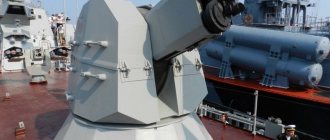
The artillery of Project 206MR missile boats includes one single-barrel automatic 76-mm AK-176 turret-type artillery mount with a barrel length of 59 calibers, located in the bow. The rate of fire of the installation is 30, 60 or 75 rounds/min. on the barrel, after 75 shots a break in shooting is required for 30 minutes. Cooling of the barrel is continuous external, with sea water at a speed of 3.5 m/s, which was passed between the casing and the monoblock. The vertical guidance angle is from -10 to +85°, and the horizontal guidance is up to 120°. The initial projectile speed is 850 m/s, the firing range at surface targets is up to 15 km. The power supply of the machines is continuous, clip-on, on both sides. The AK-176 ammunition capacity is 152 rounds. The tower is made of aluminum-magnesium alloy AMg-61 with a thickness of 4 mm.
Anti-aircraft weapons[edit | edit code]
At the stern of Project 206MR boats, for combating low-flying targets, there is a six-barreled 30-mm automatic artillery mount AK-630M with a 54-caliber barrel length, two belt magazines for 2000 rounds of ammunition and a spare belt of 1000 rounds each. Firing range – 4000 m, rate of fire – 4000-5000 rounds/min. In the standard mode, firing is carried out in 4-5 bursts of 20-25 shots, starting from the maximum range; at the distance of the most effective fire, fire is fired in bursts of 400 shots with a break between bursts of 3-5 seconds. The AK-630M had a remote control system from the SUAO MR-123/176 Vympel-A radar. Weight without ammunition is 1918 kg. The total weight of the machine with the control system is 9114 kg.