Making a motor mount
The next stage is the manufacture of a motor mount and installation of electric motors on it. I bought the commutator motors in our Hobby store; apparently they are made in China. It is not possible to establish their type, I can only say that the supply voltage was written on the price tag: 3-12V.
In terms of size, something similar is used in CD-ROMs. By the way, the choice of engines is a very important moment when building a radio-controlled boat model. You should try to select electric motors in such a way that, at the supply voltage you plan and the minimum current consumption, they provide sufficient torque. At this stage, you can also layout the model. In the case there are weight-dimensional models of electric motors, a speed controller, a receiver, steering gears and a power battery. This operation can be performed in the bathroom. It is necessary to ensure that the model is located in the water as close to the waterline as possible. You also need to avoid rolls and trims. At the same time, do not forget about the accessibility of the equipment elements and chassis after gluing the deck. At this stage, it is necessary to consider removable units for access to them. For example, superstructures or some other structural elements. It is also necessary to think in advance about the tightness of the entire structure. I chose a scheme with the entire main deck removable and the false deck made of oracal. This scheme has already been tested several times and has proven its viability. Let's return to the motor mount, I made it from foil fiberglass. Two plates were soldered perpendicularly and a brace angle was soldered between them for structural strength. The engines are attached to the frame with M2 bolts.
First, a base was cut out of foil fiberglass to which the engines would be attached. It has four holes drilled for M2 bolts and two holes for the round part of the motor housing. Then, from foil fiberglass laminate, we make a part that will be attached to the bosses mounted on the model body. I drilled two holes in it for fastening, but still, it’s better to think about where to place the third hole. Still, the three-point mount is more reliable. Then we solder these two parts at an angle of 90 degrees and install a corner between them for rigidity. As practice has shown, it is better to make the part to which the motors are attached from thicker material for rigidity.
This is what this unit looks like assembled with electric motors.
The frame itself is attached to the body of the radio-controlled boat model using plexiglass bosses with M3 threads.
Sealing the hull and ensuring buoyancy
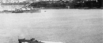
The next stage is the installation of watertight bulkheads in the hull. This is necessary in order to provide the radio-controlled boat with buoyancy when water gets inside. For a small model, this is especially critical, since even a small amount of water can lead to flooding and possible loss. Therefore, we will divide the internal volume into four compartments and install waterproof polystyrene bulkheads. Now we can carry out a buoyancy test; for this we will flood the compartments with water.
One compartment is flooded.
Two compartments were flooded.
Three compartments were flooded.
As you can see in the photo, even when three compartments were flooded, part of the radio-controlled boat remained afloat. It follows from this that it is possible to save the model in such a situation. Thus, it turned out to be divided into four compartments: bow,
the second is the electronics compartment,
third – motor
and stern
with steering gear and steering gears. But in order to prevent water from getting inside, it is necessary to seal the case well in advance. To ensure sealing of the internal volume, by gluing the body with oracal, we will glue a polystyrene side to the sides. To gain access to the electronics compartment, after gluing the bow part of the deck, a hatch is made in the bulkhead that goes up. And to make it possible to photograph the propeller shafts, holes are made in it, which will then be sealed with oracle.
Connection of electric motors with propeller shafts
After installing the propeller shafts and motors on the radio-controlled boat model, you need to think about connecting them. There are several different schemes. You can connect these nodes using a flexible connection, such as a spring, or using a universal joint. We will use the second option. To do this, on a lathe, first, from steel, we turn two bushings with a ball. Let's drill the balls for further installation of wire dowels.
Here is a photo of the already installed part on the shaft with a key.
Then we will machine two cups from steel and make cuts for the keys. Then we drill the cups, on both sides with a 1.6mm drill, and cut an M2 thread for the fixing screws.
Let's put all the details together. We machine the limiting bushings onto the shafts and solder them so that there is a slight play when the propellers are screwed on and the limiting bushings are installed.
Next, we solder bushings with balls to one end of the shaft and insert wire keys into the holes so that they move easily. You saw the end result in the photo above. We secure the cups with screws on the shafts of the electric motors. Now we insert the shafts into the deadwoods, install the motor mount in place and put everything together.
The next stage is the manufacture of propellers. How to do this is described in the article Propellers for boat models.
For now we will use untreated propellers.
Now you can apply power to the engines and check how everything works.
Making steering wheels for the model
Now we need to make rudders for the radio-controlled model of the boat Schnellboot S100. For this model you need to make 3 of them. According to the rules, rudders and propellers can be made in several larger sizes. While the central steering wheel is quite large, the side steering wheels are too small. The feather has the shape of a trapezoid, so first we will make a pattern from paper. You can take the rudders from the kit as a basis and slightly increase the area. After trying on the patterns, we will transfer them to the material from which we will make the parts. Here it is better to use stainless and well-soldered metal. For these purposes, I use sheet brass with a thickness of 0.2-0.3 mm. We make the baller from a bicycle spoke, its diameter is 2mm. One end, the length of the feather, is flattened and sharpened on an electric sharpener. These are the parts prepared for soldering.
We install the stock at the location of the axis of rotation and solder it well with a powerful soldering iron to one of the walls of the pen. Then we bend the feather and solder the back edge, then solder the ends.
This is how the raw parts turned out.
Now they need to be processed and the rudders given the desired shape.
We use the same principle to make the central steering wheel. It is somewhat more complex in form, but the essence of the process is similar to that described above. The only difference is that here the leading edge is made of copper tube.
In the end you get rudders like this
Steering gear and electronics installations
Now it’s time to install the steering gear and electronics on the Schnellboot S100 radio-controlled boat model. To do this, first, let’s think about how to mount the servo drive. I made three post-brackets from thick sprue and reinforced them with polystyrene corners. The frame itself was made from a plastic plug from a computer. It has the shape of a corner and it turns out to be quite a convenient mount.
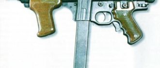
As a servo drive I used a Chinese steering machine HXT-500, weighing 8 grams. The rod was made from wire with a diameter of 1 mm with latches made from aircraft model cord.
We install everything in place, fasten the frame with self-tapping screws to the racks from the sprues.
In the second compartment we place the electronics. The receiver and speed controller will be located there.
The deck with the main superstructure has not yet been installed, but in the future they will be glued in and to allow installation and removal of electronics, a hatch will be made in the bulkhead.
We will place the batteries for the model in the engine compartment. To prevent the battery from interfering with the rotation of the propeller shafts, we will make a partition substrate, also from a computer plug. On the sides, so that the battery does not dangle, we will lay strips of porous packaging material.
Now the radio-controlled boat model Schnellboot S100 is ready for sea trials.
Installing propeller shafts and brackets
Now you need to assemble the deadwood-shaft-bracket assembly. For my radio-controlled boat model Schnellboot S-100, I used 2 mm diameter shafts from Gaupner. To avoid bending or damaging them during preparatory work, bicycle spokes, also 2 mm in diameter, were used to install and adjust the chassis of the model. Since the stern tubes are already glued into the model, now we need to fix the propeller shaft brackets. To do this, we insert shafts from bicycle spokes into the deadwoods, install the brackets in place and bend their cut parts inside the body.
Then we check the ease of rotation of the shafts in this system. If necessary, we align and bend the brackets as needed. Ultimately, we need to ensure that the shafts rotate very easily throughout this entire system. Afterwards, using a small amount of epoxy resin, we attach the propeller shaft brackets, gluing them to the PCB pads. While the resin is curing, we constantly monitor the ease of rotation of the propeller shafts and, if necessary, adjust the position of the brackets. This stage is very important, since the correct installation and fixation of the sternwood - shaft-bracket system and the ease of rotation of the shafts will in the future greatly affect the driving characteristics of the model and affect the battery consumption. After the epoxy resin has completely hardened, we once again check the ease of rotation of the catch, and if everything is in order, we finally fix the brackets, thoroughly pouring the gluing area on the textolite areas with epoxy resin. This photo shows the assembly with the brackets already bent and glued with epoxy resin.
The next stage, after fixing the brackets, is the installation of the motor mount with engines. To do this, first, on a lathe, we sharpen the bosses and cut threads into them for the screws that will secure the motor mount. In the photo above you can see that the bosses are already installed in the body. I will describe in some detail the process of installing them. I made the bosses from plexiglass, and the threads were cut for M3 bolts. To simplify the process of installing a motor mount with engines, we make two simple adaptations. We sharpen two bushings on a lathe. Since our propeller shafts and electric motor shafts have a diameter of 2 mm, we make the inner diameter of the bushings 2 mm. Their length is approximately 30mm, and the outer diameter does not matter much. Then, using these bushings, we will connect the motor shafts and propeller shafts into one whole. We screw the bosses to the motor mount, and adjusting them, we position the motor mount in the housing so that the propeller shafts rotate with maximum ease.
Preparing and assembling the case
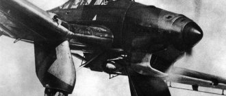
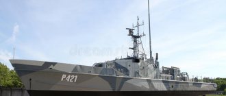
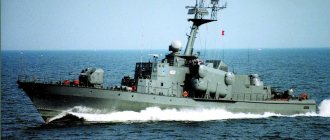
A 1:72 scale model of the S-100 torpedo boat is produced by the German company Revell. I’ll say a little about the model itself; now there are only these photos of the sprues.
Upon closer inspection, you can see that all the details are made to a high level, there are no sink marks or offsets, and very little flash. I was pleased with the large number of details and the quality of their workmanship. This model was immediately, even before acquisition, planned for radio control. Its decent length - 500mm, made it possible to make a good radio-controlled model of a boat. It was also intended to compete in the F-4A class at ship modeling competitions. Work on the model began even before the creation of the blog, but the idea was already there, so some photos of the construction process were taken. The construction of the radio-controlled boat model began with preparing and gluing the hull. In principle, the fit of the model parts is good, but for convenience, I glued the body, which is almost 500mm long, in parts.
Then, to seal the case, I poured polystyrene model glue very well over the entire seam.
Manufacturing and installation of stern tubes and helmport pipes
The next stage is preparation for the manufacture of stern tubes and helmport pipes. To do this, I turned the bushings on a lathe. For propeller shafts and rudder stocks I will use a rod with a diameter of 2 mm. The inner diameter of the stern tube bushings must be maintained strictly according to the diameter of the propeller shafts. This is necessary to ensure tightness. The pipes themselves were made from tubular elbows of antennas of the required diameter. Unfortunately, the photos of the stern tubes did not turn out well, but I think the point is clear.
The process of making helmport pipes is the same, but here the photos are good and you can see everything on them. We insert bushings into the pieces of tubes and seal them well.
Now you need to glue the stern tubes into the hull of the radio-controlled boat. To do this, we first mark on it the places for pipes and propeller shaft brackets. We make cuts and install the stern tubes without glue. To facilitate installation, you can make a device, as shown in the photo, for example, from a piece of a floppy disk body.
We set the required angle of the propeller shafts and glue the device to the hull. Now you need to make the propeller shaft brackets. We sharpen brass bushings on a lathe; here the internal diameter can be made a little larger. If during the manufacture of stern tubes and helmport pipes the internal diameter was kept strictly 2 mm, for the existing shafts, then in the brackets it can be made 2.1 mm. Since it is practically impossible to set all three points on which the propeller shaft rests on one line. And if there is even a slight misalignment, the propeller shaft will rotate slowly, which will lead to a loss of motor power, an increase in current in the circuit and unnecessary battery consumption. On a small radio-controlled boat model, battery consumption is a very important parameter. Since the space and weight of the battery are limited, we will not be able to accommodate a large capacity battery. In each bushing, we make grooves-cuts by slotting and solder brass strips there, obtaining a V bracket, according to the drawing. Plastic parts of the model can be used as templates. In the part that will be glued into the body, there are several cuts, so that later it will be easier to bend the part and glue it to the textolite pads with epoxy resin.
Now we make slots in the model body for the brackets and install them without gluing them. We check the ease of torsion of the shafts, if they rotate very easily, first we bait the stern tubes with a small amount of cyacrine and again check the ease of rotation of the shafts. If everything is in order, you can finally glue the stern tubes. After the cyacrine has hardened, you can remove the device. Now you need to glue in the propeller shaft brackets. In principle, some colleagues glue them into the body and then cover them with polystyrene diluted in glue. But after one unsuccessful model, perhaps due to the quality of the plastic of the hull, where after this composition dried, the parts moved and pinched the propeller shafts, repeated re-gluing did not help, I began to make this unit according to this scheme. Perhaps this increases the time spent, but after gluing, absolutely nothing will move anywhere due to deformation. In small pieces of fiberglass, grooves are cut for the brackets and holes with a diameter of approximately 2.5 mm are drilled around the perimeter. These plates are then installed inside the housing so that their slots align with the slots in the housing. Afterwards, holes are marked and drilled in the boat hull so that they coincide with the holes in the plate. Now parts like nails are sharpened from pieces of sprue. Their small diameter should match the diameter of the holes that are drilled in the plate and in the body. Using these parts, gluing them with model glue, we secure the plates on the inside of the boat hull. This operation is necessary in order to be able to glue the propeller shaft brackets to the hull with epoxy resin. During the curing process of the epoxy resin, it is possible to control the position of the brackets and, if necessary, adjust it. Also, after polymerization of the resin, there will be no deformation of the plastic case and displacement of the brackets. Then you can mark and glue the helmport pipes onto the cyacrine. Then, to seal and strengthen the adhesive joints, we lay them with two-component epoxy putty Epoxy Putty from Tamiya.
Now you can putty the installation sites of the stern tubes and plates under the brackets. For this I use two-component car putty BODY SOFT.
BODY SOFT automotive putty hardens quite quickly; after just a few hours the body can be treated. I do these things at night so that by the next evening everything will definitely harden.