Details Category:
AUTOMATIC WEAPONS
, a weapon in which the pressure of powder gases developed during a shot is utilized not only for ejecting a bullet, but also for reloading, i.e., for opening the bolt, ejecting the cartridge case, cocking the mainspring, inserting a new cartridge into the chamber and closing the bolt; in this case, the shooter only has to aim, pull the trigger and fill the magazine with new cartridges. The first idea about such a weapon arose more than 70 years ago. In 1854, Heinrich Bessemer took out a patent for a cannon loaded from the treasury, equipped with a unitary cartridge, the bolt of which opened automatically after the shot, by the pressure of the powder gases. The first project of an automatic gun appeared in 1863, when the American Regulus Pilon took out a patent for a gun with a bolt sliding back after firing, which then moved forward again to its original position by the cocked recoil of the spring. In 1866, the English engineer Joseph Curtis built an automatic repeating shotgun with a rotating drum magazine; the recoil of the shot, together with the work of the springs compressed by the recoil, automatically opened, loaded and closed the bolt. The first practical application as an automatic weapon was the automatic cannon invented in 1883 by Maxim, which was introduced into service in some armies; then the development of automatic weapons made significant progress only at the end of the last century, when the Maxim machine gun was designed; its enormous military significance was confirmed by the experience of the wars: the Anglo-Boer and Russian-Japanese. Since then, vigorous experiments have been carried out in all states to develop automatic weapons. Currently, after the experience of the World War, automatic weapons in the form of heavy and light machine guns, machine guns, automatic rifles and cannons began to gradually replace the previous weapons.
The classification of automatic weapons developed by V. Fedorov can be presented as follows.
I. The action of powder gas pressure through the bottom of the cartridge case on the bolt, the use of recoil
Shutter recoil. Systems with a fixed barrel, operating by direct pressure of powder gases on the bolt
A. Systems without bolt coupling. Browning autopistol: the bolt adheres to the rear edge only under the pressure of a spiral spring, one end resting against the stationary frame of the pistol, and the other against a special tube connected to a movable casing; when fired, the pressure of the powder gases through the bottom of the cartridge case throws the bolt back, the cartridge case is extracted, the hammer is cocked and the spring is compressed, which returns the casing to its original position; this system is applicable g.o. for weapons with low pressure of powder gases, as well as with short barrels, where the bullet quickly leaves the barrel; their main advantage is the simplicity of the device.
B. Systems with a liner that delays the ejection of the bolt. Thomson's system: the desire to somewhat delay the release of the bolt so that its opening could occur only at the moment when the bullet leaves the barrel, resulting in the appearance of weapons with various bolt-delaying devices based on friction; in the Thomson system, a bronze liner is placed between the bolt and the supporting plane of the box, the extension of which, when fired upward, under the influence of gas pressure through the bottom of the cartridge case onto the edge of the bolt and delays its throwing back (Fig. 1).
B. Systems with a bolt clutch to delay the rapid opening of the barrel are divided into two subgroups: a) With a clutch using side lugs (Manlicher rifle): the bolt is engaged with the receiver using lugs that fit into an annular groove on the receiver when turning , similar to a 3-line clutch. rifle arr. 1891, with the only difference that these grooves are made inclined; Thanks to this device, when fired, under the action of the pressure of the powder gases on the bolt, the bolt self-opens with the lugs sliding along the inclined grooves of the box (the sliding also delays the release of the bolt somewhat when fired). b) With lever clutch (Schwarzlose machine gun, Fig. 2 and 3):
the barrel is closed by a bolt DD, coupled to the box in which it moves, in place A using two articulated rods AB and BV; the pressure of the powder gases through the bottom of the cartridge case on the bolt tends to throw it back; since the hinge axis A is connected to the stationary frame of the machine gun, then simultaneously with the movement of the bolt, the deployment of the rods begins; the compressed return spring then returns the bolt to its original position.
Of all the delaying devices described above, the presence of articulated rods in the Schwarzlose machine gun represents the most effective means. Systems with a fixed barrel that have a bolt clutch have the significant disadvantage that despite the slower opening of the bolt, which guarantees shooting safety, the opening in them begins simultaneously with the movement of the bullet along the channel, i.e., even when there is some pressure in the chamber , and the extraction of cartridges in these systems is significantly more difficult. This circumstance necessitates pre-lubrication of the cartridges, otherwise cases of non-extraction of cartridges are possible: both the Schwarzlose machine gun and the Mannlicher rifle fire only lubricated cartridges. To eliminate these shortcomings, it was necessary to abandon a very large advantage of automatic weapon designs, namely, the immobility of the barrel, and turn to the design of systems with movable barrels, where the barrel, receiver and bolt move together until the bullet leaves the end of the barrel.
Recoil of the bolt with the barrel. Systems operating by recoil of a moving barrel
A. Short stroke systems. 1) System with direct movement of the shutter, a) Clutch engagement in the horizontal plane. Mauser system (Fig. 4):
the system has a movable barrel; adhesion of the bolt to the barrel is achieved using two symmetrically located rotating latches ab
, the rear projections of which fit into the corresponding recesses of the bolt;
when fired, the pressure of the powder gases on the bottom of the cartridge case throws the bolt back, and since the latter is engaged with the receiver using latches ab
, all the moving parts move back together, and the return spiral spring is compressed;
this joint movement continues until the front ends of the latches ab
touch the special bevels of the fixed tire
bb
connected to the system box; this sliding along the bevel will rotate the larvae and disengage the bolt from the receiver; upon release, the bolt will continue to move backward by inertia, compressing the return spring and performing all the actions necessary for reloading. b) Clutching in a vertical plane. Fedorov system (Fig. 5, B, A and C):
the barrel is movable, having its own return spring; adhesion of the bolt to the barrel is achieved using two larvae ab
, symmetrically located in the vertical plane;
these larvae in their front part have round protrusions a
, which fit into the corresponding round recesses on the side surfaces of the trunk;
thanks to these protrusions, the larvae can rotate, as can be seen from the drawings; on their rear ends the larvae have protrusions b
, holding the protruding trunnions of the bolt
c
;
when fired, the gas pressure on the bolt tends to throw it back, and since it is linked to the barrel with the help of larvae, all the moving parts - the barrel, the larvae, the bolt - begin to move backward; this joint movement occurs until the special hooks of the larvae r
, located on their lower planes, rest against the fixed ledges
d
of the system box, rotating the larvae and disengaging the bolt from the barrel, as can be seen from Fig. 5, B; under the influence of the acquired manpower, the bolt continues its movement, compressing the return spring. Mauser system (Fig. 6a and 6b):
clutch of the bolt with the receiver is achieved using one cylinder ab
, located in a vertical plane;
the larvae can rotate about the axis a
, passing through the receiver, which is movable when fired, as can be seen from a comparison of the two figs;
the clutch is made using two protrusions dd
passing through the opening of the receiver into the corresponding recesses of the bolt;
the lower spout of the larva rests
on the bevel
a of
the stationary box of the system;
when fired, the pressure of the powder gases throws the bolt back; since the bolt is engaged by the cylinder with the receiver, the latter, together with the barrel screwed into it, moves backward; this happens until the nose of the larva in
, sliding along the inclined bevel
g
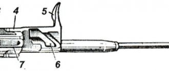
, rests against the ledge of the stationary box; with this movement, the cylinder rotates and the bolt disengages from the barrel; under the influence of the acquired manpower, the bolt will continue its movement, compressing the bolt spring. A similar clutch with a lower latch is implemented in the Mannlicher system. c) Lever clutch. Maxim machine gun (Fig. 7):
the system has a movable barrel connected to two longitudinal plates of a special frame, between which the ab
, locking the barrel, bloodworm
in
and connecting rod
gd
;
all three parts are connected to each other by hinges in
,
d
,
d
, and the last hinge passes through the rear end of the frame plates and is connected to the connecting rod motionlessly, i.e. so.
example, that if this axis turns, then the connecting rod itself must turn; hedgehog
is mounted on this axis on its right side , resting with its rear end
on
the roller
h
; The rear end of a spiral tension spring is attached to the handle using a chain, while its front end is attached to the stationary frame of the system.
When fired, the powder gases tend to throw the lock back, but since it is connected by a crank and a connecting rod to the machine gun frame via the d
, and the middle axis
z
is located slightly above the two extreme axes
d
and
c
, at the same time adjacent to the top of a special wall - then initially these parts, i.e. the crank, the connecting rod and the lock, retain their position that they had before the shot , and move back together, moving the frame behind them, and therefore the trunk connected to it;
this happens until the handle hedgehog
, sitting on the
d
, slides onto the roller
z
, as shown in Fig.;
rotation of the handle will, in turn, cause rotation of the d
, and therefore the connecting rod
d
- all parts will come to position B; in this case, the lock will receive an accelerated movement compared to the frame and barrel, it will open the barrel, and the cartridge case will be ejected from the chamber; from the extreme position of the moving parts, the stretched return spring will then return all parts to their original position; since the moving parts in this system are very massive, to increase the force that throws them back, a muzzle is fitted to the system, the idea of which is that the powder gases ejected from the barrel after the bullet act on the front edge of the muzzle and increase the speed at which the barrel, frame and other moving parts are thrown back. Borchardt-Luger system (Fig. 8):
shutter ab
linked to the receiver
VG
using two hinged strips
de
and
ez
;
the middle hinge is
located slightly lower than the two outer ones;
thanks to this arrangement, the pressure of the powder gases when fired pushes the bolt back along with the hinge bars and the receiver; this joint movement occurs until the rollers sitting on the middle hinge e
touch a special inclined plane
zz
cut on the stationary box of the system; sliding of the rollers along the inclined plane will cause the hinges to roll up and the bolt to move faster, and the spent cartridge case will be extracted; when the receiver moves backward, a special return spring (not shown in the figure) is compressed, which then returns the moving parts to their original position.
2) Rotating shutter systems. In the initial samples of automatic weapons with a barrel that moved when fired, some designers used systems with a rotating bolt (Tokarev, 1st sample). Such systems had the significant inconvenience that the bolt handle rotated upward in front of the shooter’s eye and made it difficult to calmly aim; they are not currently used.
3) Systems with a side-moving shutter. Bergman system (Fig. 9, A and B):
has a movable trunk with a special process, the protrusion of which is
fits into the corresponding recess of the shutter
bv
;
the bolt can move slightly in the horizontal plane, moving away from the protrusion a
to the right and thereby disengaging from the barrel;
this movement occurs when a shot is fired under the influence of recoil, when the moving parts, the barrel and the bolt, are thrown back by the pressure of the powder gases; during this movement, the inclined plane of the bolt g
jumps onto the inclined plane
d
of the stationary box, moving the bolt to the right and freeing it from the barrel, and further movement compresses the return spring
g
.
4) Systems with a swinging shutter. Madsen system (Fig. 10, A and B):
the barrel is movable, screwed into the receiver ab
;
shutter vv
, swinging in a vertical plane about the
z
;
lever de presses on the shutter
;
under the action of the spring w
, a special bolt pin
z
, located on its right side, fits into the groove
kkkk
, planed in a stationary box.
When fired, the powder gases throw the bolt back, and with it the receiver, which is connected to the bolt by the z
;
at the same time the return spring w
;
When the bolt moves backward, due to the sliding of its pin along
the inclined and longitudinal grooves
kkkk
, the bolt swings in a vertical plane, opening the barrel and throwing the spent cartridge down.
B. Long stroke systems. In addition to the systems described above with a short recoil of the barrel, the stroke length of which is calculated only for the time the bullet passes through the bore, there are also some systems with a long recoil, reaching the length of the cartridge. These systems are more bulky and heavy and are now considered obsolete.
Recoil of all weapons. Systems with a fixed barrel operating by recoil of the entire weapon
Systems with a slide and ejection of the bolt by remaining gas pressure. Mauser system: the bolt is a bar supported from behind by two symmetrically located larvae, the front ends resting on the rear edge of the bolt, and the rear ends on the corresponding edges of the receiver; to be able to disengage the bolt, it is necessary to move these larvae apart, and the bolt will be thrown back by the pressure of the powder gases remaining in the chamber; when fired, when the entire rifle recoils back, the slide tends to remain in place by inertia, i.e., in relation to the rifle, the slide moves forward, which, due to the presence of inclined grooves, moves the larvae apart, releasing the bolt; the thrown bolt compresses both the return and mainsprings. To open the bolt for the first time, it is necessary to first move the slide forward to spread the larvae, and then move the bolt back.
see also
Other weapons:
- Madsen machine gun
- Chauchat
- Fedorov Avtomat
- Farquhar Hill rifle
- Leichtes Maschinengewehr Modell 1925 "Lmg 25"
- Huot Automatic Rifle
- Morse submachine gun
- Knötgen automatic rifle
- Automatic rifle Zig
- Colt Automatic Rifle
- M27 Infantry Automatic Rifle
- Howell Automatic Rifle
- Rieder automatic rifle
- SIG SG 510
Other related articles:
- Semi-automatic rifle
- Assault rifle
- Combat rifle
- Marksman rifle
- Sniper rifle
- Light machine gun
- Squad automatic weapon
- List of firearms
II. The effect of partial pressure of powder gases on special parts of the system
Systems with a fixed barrel, operating by pressure of powder gases discharged through a transverse channel in the barrel
A. Systems with a piston moving the entire length of the bolt. Lewis system (Fig. 11):
when fired, part of the powder gases following the bullet rushes through the side channel A, cut in the barrel wall, into the under-barrel tube of the gun and throws back the piston B moving in it; the piston is integral with a gear rack T, the teeth of which are engaged with a gear wheel D; a plate spring E is placed inside the wheel, working on torsion; on the rear limb of the rack G there is a striker G placed on top; the striker enters through the inclined groove II into the bolt 33, which is a cylindrical block and has combat protrusions KK, which enter the corresponding recesses in the machine gun box when the bolt is turned; throwing the piston back through the thrown rack G will cause the rotation of the gear D and the charging of the spring E; in addition, the straightness of the movement of the rack with the movement of the firing pin entering the inclined groove II of the bolt 33 causes the bolt to rotate and its lugs to emerge from the barrel recesses - the bolt is disengaged from the box and thrown back under the action of the continued movement of the piston; the twisted spring E returns the rack and bolt to their original position, and the movement of the striker along the inclined groove rotates the bolt and engages it with the box. Hotchkiss machine gun 1st model (Fig. 12):
powder gases following the bullet through channel ab
enter a special gas chamber in which the piston
vv
, throwing it back and compressing the spiral return spring
d
;
the clutch of its bolt is
carried out using a special, rotating
bar
;
This bar, at
its front end, is hingedly connected to the rear end of the bolt;
the rear end of the bar fits into the hole of the hook-shaped protrusion located at the rear end of the piston; a special side axle of the strip w
, in addition, fits into an inclined groove
zz
, planed in a stationary machine gun box, this groove then goes into a longitudinal one;
when fired, the shutter may not. thrown back, it is connected by a bar to
the box;
opening of the shutter can occur only when the piston moves backward, when the hook-shaped protrusion moves back somewhat, resulting in: 1) the rear end of the bar coming out
of the hole, 2) its rotation, due to the presence of the bevel
kk
of the piston, and 3) the location of its side pin on the continuation longitudinal groove
zz
;
at the end of this initial movement necessary for decoupling, the protrusion of the piston m
rests on the cut of the bolt and throws it back, and further compression of the return spring
d
;
To enhance the effect of gases, the volume of the gas chamber can be increased or decreased using the regulator l
.
B. Piston systems that produce a thrust that pushes the bolt back to its full length. Colt machine gun (Fig. 13):
powder gases following the bullet, rushing into the side channel, throw the connecting rod AB back (which can be seen from a comparison of the 1st and 2nd positions of parts A and B); the crank VG connected to the connecting rod drives the guide bar DE, which moves the bolt; the latter is a cylindrical block that has a rocking motion in a vertical plane; in the position before the shot, the bolt has a slightly inclined position, and the lower part of its rear edge rests against the special side planes of the LL box, which are recoil arms, as shown in the schematic drawings of the bolt clutch; when the bar DE goes back, a special bolt 3, fixedly inserted into this bar and entering the oval inclined slot KK on the lower protrusion of the bolt G, sliding along the slot, lifts the rear end of the bolt up, and the bolt is disengaged from the recoil arms of the box; the return springs located in the corresponding tubes M are compressed and then bring all the moving parts to their original position.
The benefits of systems with removal of powder gases: 1) having a late opening, i.e. at the moment when the bullet leaves the barrel, it is possible to use a stationary barrel in these systems, which greatly simplifies the system and eliminates a number of delays when firing; 2) there is no need to resort to pre-lubrication of cartridges to improve extraction; 3) you can adjust the volume of the gas chamber and the throwing force of the piston and bolt; 4) a large reserve of power of powder gases in case of operation under unfavorable conditions. Disadvantages: 1) the sharpness of the movement of the ejected parts, caused by the short time during which the gases act on the piston (the bullet travels the distance from the gas outlet to the muzzle); 2) the possibility of contamination of the underbarrel tube; this drawback is currently eliminated by the corresponding design of the pipe and piston (in the Hotchkiss system of the 2nd model; in the Colt machine gun there is no under-barrel tube with a piston fitted in it). A slight decrease in the initial speed, due to the removal of part of the gases, has no significance in practice.
B. Systems with a piston that only opens the bolt (but not ejects it). Chei-Rigotti rifle; The bolt is thrown back after it is opened by the powder gases remaining in the chamber.
Systems with a fixed barrel, operating under the pressure of powder gases that eject a movable muzzle
Muzzle weapons are more complex than other systems; a sharp movement of the muzzle causes, in addition, a very sensitive shock to the weapon, which affects shooting accuracy; these systems were not widely used (Puteaux machine gun, Baig automatic rifle).
Systems with a fixed barrel, operating by pressure of powder gases removed from the chamber through the channel of a special cartridge case
The need for special cartridges, more stringent requirements for the primer, which acts as a seal, as well as difficult extraction of cartridges due to relatively early opening, are such big disadvantages that this system has not become widespread.
CONTENT
- 1 History 1.1 Mannlicher
- 1.2 Cei-Rigotti
- 1.3 Chauchat
- 1.4 Lewis gun
- 1.5 Fedorov Avtomat
- 1.6 Browning Automatic Rifle
- 1.7 ABC-36
- 1.8 FG 42
- 1.9 Sturmgewehr 44 (assault rifle)
- 1.10 AK-47
- Rifle 1.11 M14 (battle rifle)
- 1.12 FN FAL
- 1.13 H&K G3
- 1.14 M16 rifle
- 1.15 HK33
- 1.16 5.56 mm NATO
- 1.17 Steyr AUG (bullpup rifle)