Safety mechanisms and devices of small arms
Small arms, by definition, must be safe to handle. To ensure safety, weapons are usually equipped with devices that make it impossible to accidentally fire while on a hike, when moving, when changing a firing position, etc., by blocking the firing mechanism or separating it from the trigger mechanism, or by blocking or separating moving parts. Such devices and parts are called fuses.
GSh-18 pistol with an automatic safety device mounted on the trigger.
Safety mechanisms and devices, depending on their purpose, are divided into three main groups. The first group includes mechanisms that ensure the safe operation of automatic small arms, the second includes mechanisms and devices that ensure safe handling of weapons, and the third includes devices that protect weapon parts from contamination and damage.
Safety mechanisms that serve to ensure the safety of the automation make it impossible to fire a shot when the bolt is unlocked. Since a shot with an unlocked bolt, in addition to breaking parts of the weapon and its failure, poses a great danger to the shooter himself, during the operation of the weapon it is necessary to pay special attention to ensuring the reliability of the operation of these mechanisms.
Safety mechanisms that ensure the impossibility of firing when the bolt is unlocked have a wide variety of operating principles, which largely depend on the device and type of trigger mechanisms. Most often, protection functions are combined in one mechanism with other functions necessary for the operation of the automation.
If the firing mechanism is powered by a mainspring, then protection against firing when the bolt is unlocked is provided by self-timers, the operation of which is associated with the operation of the locking mechanisms.
If the impact mechanisms are powered by a recoil spring, then protection against shots when the bolt is unlocked is, as a rule, provided by the direct connection of the impact mechanisms with the locking mechanisms. For example, in a DP light machine gun, the firing pin can exit the hole in the bolt only after the lugs are fully retracted, i.e. completely locking the shutter.
Some types of automatic small arms have double safety, which makes it possible to fire when the bolt is unlocked. For example, in the SKS self-loading carbine, this protection is carried out by connecting the operation of the self-timer with the operation of the bolt locking mechanism and by connecting the operation of the impact mechanism with the operation of the bolt locking mechanism. The first of these connections ensures that the bolt stem can press the self-timer rod only in the locked position of the bolt, and the second ensures that the trigger strike on the firing pin can also occur only when the bolt is locked.
Safety mechanisms and devices that ensure safe handling of weapons place firing mechanisms in positions that prevent their operation. Safety mechanisms must meet the following requirements: ensure reliable operation, quickly turn on and off, be easy to maintain, and have a simple design.
The OTs-23 “Dart” pistol has a safety, which also serves as a fire type translator.
Its flags are located on both sides of the shutter casing. They allow you to put the pistol on safety. The reliability of the safety mechanisms is necessary because accidental shots when servicing a weapon can cost human casualties among service personnel both in combat and in training situations. The speed of turning the fuses on and off is required to speed up the weapon's combat readiness, which determines one of the essential combat qualities of the weapon. The convenience of determining the position of the fuses characterizes both the reliability of the fuses and the speed of their switching on and off.
Therefore, there are also fuses that eliminate the possibility of an accidental shot. They are activated by the shooter. Depending on the nature of the shooter’s impact on the fuses, they are divided into automatic and non-automatic.
Automatic fuses include those fuses that do not require special techniques to turn on - they are activated independently of the shooter (most often due to the elastic forces of the springs), and are turned off by the shooter in preparation for a shot before aiming by moving the button or turning the lever by hand, or when grasping the neck of the butt or pistol grip. An example of such a fuse is the fuse of the Degtyarev DP light machine gun. In the DP machine gun, the safety lever in the form of a lever is mounted under the neck of the butt so that the shooter, when clasping the neck of the butt with his right hand, naturally presses this lever and releases the sear. When you remove your hand from the neck of the butt, the safety lever rotates under the action of its spring and locks the sear. In the Colt M 1911, Heckler and Koch R.7 pistols and the Uzi submachine gun, the automatic safety is activated when the shooter’s hand clasps the pistol grip, and in the Glock 17 pistol, pressing the trigger is possible only after pressing the automatic a safety device built into the design of the trigger itself.
All fuses that exclude the possibility of an accidental shot ensure a break in the kinematic connection between the sear and the trigger, and sometimes additionally deprive the striker of mobility (for example, in the Makarov PM and Stechkin APS pistols). This is achieved by locking or turning off the main part of the trigger mechanism (sear, trigger). Thus, in the Walter R. 38 pistol, the safety mechanism provided triple protection against accidental shots, since its design made the following impossible: advancing the striker when the bolt was not completely locked; cocking the hammer to its full extent with the bolt in the forward position; breaking of the cartridge primer by the firing pin even when the trigger is hit, since the firing pin was locked by the protrusions of the safety axis.
In the SIG-Sauer P.228 pistol, a safety release lever is mounted on the left side of the frame above the magazine latch.
When lowering it down, it raises the sear, disengaging it from the trigger, which, under the action of the mainspring, rotates until it engages the safety groove (trigger) with the sear, thus eliminating direct contact with the firing pin. Due to their high reliability, modern models of automatic small arms now have fuses with rigid sear locking.
Non-automatic safeties include those that require special techniques on the part of the shooter to turn them on and off, such as turning a flag, pressing or moving a button, etc.
Non-automatic fuses are the most common among modern small arms. Although they require special techniques to turn them on and off, they usually provide the greatest simplicity of operation and good reliability of operation.
In this case, the safety device consists of: the fuse itself, a control button or flag, a latch and springs.
If the fuse, when installed in the “safety” position, moves progressively at the moment of locking or turning off, then in this case it is most often controlled by a button and is therefore called a push-button. An example of a push-button fuse would be the fuse in the German single machine gun MG.42. If, when installed in the “safety” position, the fuse turns with a flag, it is called a flag. In modern small arms, flag fuses of various designs are the most widely used. Thus, one of the first safety pins implemented in automatic short-barreled firearms was the fuse of the German Parabellum M 1900 pistol, mounted in a groove on the left wall of the frame. Using a lever with a flag, which was also located on the axis on the left side of the frame, the fuse could move and occupy two positions: “fire” and “safety.” When the flag was turned back and down, the inscription “Gesichert” was revealed, the front end of the lever rose and raised the fuse itself, which prevented the sear from turning and the bolt from moving back for cocking. When the flag was turned forward, the inscription “Gesichert” was closed, the front end of the lever lowered and carried the fuse along with it, disengaging from the sear.
All non-automatic fuses, depending on the principle of their operation, are divided into locking and switching, and depending on what part they act on - into trigger, sear, trigger and combined.
The safety lever of the Beretta 96 pistol, mounted on the bolt casing, blocks the firing pin and at the same time serves as a lever for safely releasing the hammer. Locking
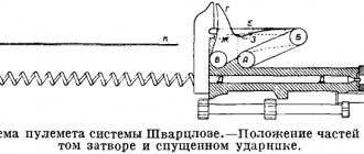
fuses include mechanisms that place the trigger mechanisms in positions in which they cannot operate due to the locking of one or more details of these mechanisms. A typical example of such fuses is the safety mechanism in the Shpagin PPSh submachine gun, which locks the moving system in the forward or rear position. The PPSh submachine gun mod. 1941, the safety locks the bolt in the cocked and deflated positions. This fuse is made in the form of a bolt, mounted on the bolt reloading handle and held by a latch in two positions. When putting the bolt on safety, the fuse slide is inserted into the corresponding cutouts in the cover of the bolt box and fixes the bolt in the front or rear position. Fixing the bolt of the PPSh is of great importance to protect against accidental shots from the inertial movement of the heavy bolt when transporting the weapon.
Switching safety mechanisms perform the same role as locking mechanisms by turning off one or more parts from the kinematic chain of trigger mechanisms. These fuses are usually mounted in the firing mechanism.
One of the most typical examples of these fuses can be considered the so-called.
safety platoon. It is widely used in short-barreled weapons. On the trigger in front of the combat cock there is an additional protrusion - a safety cock, which is highly reliable, by which the trigger is held after the weapon is put on safety. The cut is made deep enough and the sear cannot fall off it. Even if a pistol with the hammer cocked falls to the ground or receives a sharp blow and the hammer falls off the cock, the shot will not fire. Due to the fact that the trigger is not pressed, but the sear is pressed against the trigger under the action of the spring, it will put the trigger on the safety cock. Safety-translator flag for the G.3 assault rifle.
The safety cock is found in the designs of domestic Tokarev TT pistols; Makarova PM; Stechkin APS, American Colt M 1911A1 and many others.
In revolvers, along with a safety cock, they also use a hammer release, as well as a transfer block.
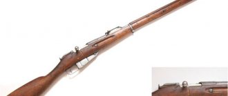
The trigger release was used in the Nagan revolver mod. 1895. In the design of its firing mechanism, the trigger first struck the primer, and then returned a little back under the action of the mainspring to set the safety cock.
The transfer block was used in weapons such as Sterling revolvers. In Smith-Wesson revolvers, protection against an accidental shot was carried out using a blocking rod. In fact, it provided an automatic fuse. In its normal state, the locking rod kept the hammer retracted from the firing pin and allowed the shot to be fired only when the trigger was fully depressed, when it dropped down, allowing the hammer to strike the firing pin.
In modern automatic small arms, fuses are widely used, which perform additional functions. Very often, the flag fuse is assigned, along with its main function - blocking parts, other tasks. Thus, in the Makarov PM pistol, when the safety is engaged, the hammer is safely released (if it was cocked), the firing pin and the entire firing mechanism are blocked, and the possibility of the hammer hitting the firing pin and reloading of the weapon is eliminated.
In the Stechkin APS automatic pistol, the safety lever additionally serves as a fire switch from single-fire mode to automatic and back. When the fuse box is turned forward, the cams of its axis push the striker back and close it. At the same time, the lower feather of the sear rests against the hammer platform and does not allow it to be cocked, and the edge of the translator-safety extends beyond the left protrusion of the frame and fixes the bolt with the frame.
In the G.3 assault rifle, the reloading handle can be inserted into the safety groove, complementing the main safety switch.
One of the most successful designs of the safety switch was implemented in the Kalashnikov AK assault rifle, in which the type of fire switch (translator) is also a fuse made in the form single rotating part. Kalashnikov himself later recalled this with pride: “We were very happy that we managed to solve the problem of the fire translator. It now began to perform several functions: it provided switching of fire from single to automatic and to safety, at the same time closing the groove for the reloading handle, thereby not only eliminating the possibility of cocking the bolt, but also protecting the receiver from dust and dirt getting inside.” In the upper “safety” position, the safety lever locked the trigger, limiting the movement of the bolt frame; in the middle position, marked with the letters “AB”, the firing mode switch was set to automatic fire, and in the lower “OD” - to fire with single shots. This solution for the location of the fire type switch turned out to be very successful. The designer foresaw in advance a situation where, under stress conditions in combat, the shooter, when removing the machine gun from the safety, would inevitably squeeze the translator flag to the lowest position - i.e. shooting with single fire. Because this is how a weapon should be used in almost all difficult situations. And to ensure automatic shooting, the shooter will consciously move the translator flag to the middle position for firing in continuous bursts. In addition, such a successful and simple design solution of the translator-fuse partially solved the problem of eliminating contamination of the weapon, since in the stowed position the flag of the translator-fuse covered the groove of the receiver cover along which the reloading handle moved, which prevented dirt from getting inside the receiver.
In the Micro-Galil assault rifle, the translator-fuse flag is duplicated by a flag on the left side of the receiver.
In some cases, for greater reliability of an automatic weapon, both automatic and non-automatic fuses are mounted on it, as for example in the American Colt M 1911/M pistols 1911A1. The non-automatic fuse consisted of an axis, a flag with a notch for moving from the “fire” position to the “fuse” position and back, a tooth for interacting with the sear and trigger. The position of the fuse was fixed with a stopper. The non-automatic safety can only be engaged when the hammer is cocked. When set to the “safety” position, the flag is turned upward, while its tooth stops the sear, preventing the trigger from turning even when the trigger is pressed. The fuse comb went into a recess on the left side of the bolt casing, thus eliminating the possibility of cocking it. The automatic safety was placed in the cutout of the pistol grip and was a double-armed lever that swung on the same axis as the non-automatic safety. The lower rear part was shaped like a pistol grip, the upper part had several cutouts and one large protrusion that interacted with the trigger rod. The right feather of the trigger spring forced the automatic safety to rotate on its axis all the time so that its upper shoulder came out of the handle, and the protrusion was pressed against the trigger rod and did not allow it to move. Only when you wrapped your hand around the handle did the safety rotate inside the handle, so that the protrusion came out of engagement with the rod and it became possible to release the hammer.
The third group includes fuses that protect mechanisms and weapon parts from contamination and damage. These fuses come in a wide variety of designs and are made in the form of various covers and shields.
The most widely used are covers for closing windows in the receiver and shields for protecting sighting devices. The covers covering the receiver windows are usually equipped with devices that automatically open them when loading. For example, in the American M 3 submachine gun.
In some types of weapons, in order to protect against contamination, caps are also used to cover the muzzle of the barrel.
Sergey Monetchikov Photo from the author’s archive
LOCKING MECHANISM OF FIREARMS Russian patent 2022 according to IPC F41A3/22
Field of technology
The invention relates to a device for a firearm with a locking mechanism (bolt).
State of the art
In the prior art, technical solutions are known: US 6820533, published on November 23, 2004, RU 2331831, published on August 20, 2008, RU 2386098, published on April 10, 2010, DE 3210427, published on September 22, 1983. In the design of these known solutions, with the help of a bolt frame, the bolt performs a longitudinal sliding movement with a stationary barrel to firmly lock the barrel bore, remove cartridges after a shot, cock the hammer, feed the next cartridge into the chamber and transmit the hammer blow through the firing pin to the primer. The disadvantage of the known solutions is that they are all of the type of longitudinally sliding valves with a turning handle. The specified bolt is driven by the muscular force of the shooter, and the force of the shooter necessary for the operation of the bolt is transmitted using the handle. In this case, the shooter imparts to the bolt not only a translational movement, but also a rotational one, due to which the bolt rotates around its longitudinal axis at a certain angle sufficient for the bolt lugs to move beyond the corresponding lugs of the receiver. Gates of this type perform locking due to the entry of the combat (locking) protrusions of the bolt stem into the corresponding grooves of the receiver or barrel. Typically, such bolts include a spiral spring in their design.
There are known analogues of the claimed technical solution AT 14590 U1, publication date 02/15/2016, AT327745 B, publication date 02/10/1976, in which a longitudinally sliding bolt is opened with automatic rotation of the bolt cylinder, the lugs (lugs) of which fit into the corresponding grooves of the barrel boxes. However, the disadvantages of the known solutions are their complex design and reduced operational reliability in difficult operating conditions.
The closest analogue - the prototype of the proposed solution - can be patent US 3618457 A, publication date - 11/09/1971, IPC F41A 3/26, 5/18. This source discloses a firearm that contains a bolt box, a barrel assembly with a chamber and a moving system. A moving system moves in the bolt box, consisting of a bolt frame with a bolt with lugs placed in its channel. The movement and rotation of the shutter is carried out by the leading finger, which interacts with the surface of the shutter shank, the driven surface of which is a helicoid. As follows from the known solution, the driven surface is located on the shank of the valve, and the leading surface of the frame (smooth axis) has a circular cross-section and interacts with the driven screw surface of the valve in an unfavorable way - along a line, which leads to an increase in the specific pressure in the contact zone of these parts and to their increased wear. Moreover, under unfavorable friction conditions, for example, friction of dry parts under prolonged load, due to the large energy consumption of the bolt frame for unlocking and locking the bolt, such a mechanism will be prone to incomplete rollbacks and stopping of the moving parts.
Thus, the objective of the present invention is to develop a firearm with a locking mechanism (bolt), which can be used in difficult conditions generated by a number of external factors and their combination: pollution, dust, thickening of the lubricant and its complete absence. The appearance of any of these factors leads to a decrease in the speed and energy of the moving parts, and at a certain value of these factors, the moving parts stop and a failure to fire occurs.
The technical result of the claimed invention is to overcome the above disadvantages and create a simple and reliable mechanism for locking firearms, which has reduced energy losses of the bolt frame to overcome friction in the bolt-drive pin assembly when turning the bolt and increased reliability of operation in difficult conditions, increasing the wear resistance of interacting elements .
Disclosure of the Invention
The technical result is achieved by the fact that the claimed locking mechanism of a firearm consists of a bolt box, a barrel assembly with a chamber and a movable system consisting of a bolt frame with a bolt with lugs placed in its channel, a leading finger, and there are guide elements in the bolt box, along which the specified movable system moves, consisting of a bolt frame with a bolt with lugs placed in its channel, and driven surfaces are made on the bolt shank; on both sides of the leading finger of the bolt frame there are sections that interact with the driven surfaces of the bolt shank on the shoulder equal to or close to the radius of the bolt shank, while the driven surfaces are made in the form of a helicoid with a variable pitch, the axis of which is coaxial with the bolt shank; additionally, on the locking driven surface there is a beveled section with an angle between its working surface and the surface of the leading finger close to the self-braking angle.
In this case, the leading pin is located across the longitudinal axis of the frame and above/below it.
In addition, the driven surfaces are separated by a longitudinal ridge.
Also, the technical result is achieved by the fact that the firearm contains a stock, a bolt box, a receiver assembly, a trigger guard, a muzzle device, a moving system and a magazine, while the bolt box contains the claimed locking mechanism.
The essence of the invention
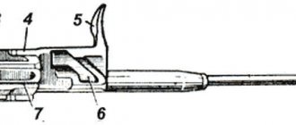
In fig. 1 shows a locking mechanism (shutter) according to the present invention.
In fig. Figure 2 shows the driven surfaces A, B and C on the gate shank.
In fig. Figure 3 shows a general view of the locking mechanism when the bolt is locked
In fig. Figure 4 shows a general view of the locking mechanism when the bolt is open.
In fig. Figure 5 shows a general view of the locking mechanism at the beginning of the roll-up, when the leading pin rests on the area at the self-braking angle.
In fig. 1-5 the following notations are used:
1 — bolt box;
2 — barrel with chamber;
3 — bolt frame;
4 - shutter;
5 - leading finger.
A design of a firearm with a locking mechanism is proposed. The weapon, in particular, consists of a bolt box 1, a barrel assembly with a chamber 2 and a moving system. The bolt box contains guide elements (grooves) along which the movable system moves, which includes a bolt frame 3 with a bolt 4 placed in its channel with lugs. The movement and rotation of the shutter is carried out by the leading finger 5, located transverse to the longitudinal axis of the frame and above/below it, which interacts with the shaped driven surfaces A and B on the shank of the shutter 4. The driven surfaces are made in the form of helicoid sections with variable pitch, the axis of which is coaxial with the shank of the shutter 4. A gentler rise of the spiral at the initial stage ensures ease of unlocking the rotary shutter 4, while a steeper lifting step at the final stage provides a shorter stroke of the moving system required to fully rotate the shutter 4. Thus, it ensures ease of unlocking the shutter 4 and, in at the same time, the relatively short stroke of the moving system required for unlocking. On the locking driven surface A there is a beveled section B with an angle between its working surface and the surface of the driving pin 5 close to the self-braking angle. The driven surfaces A and B are separated by a longitudinal ridge in order to bring them as close as possible in cross-section to the diameter of the bolt shank 4 and, accordingly, to the maximum radius of application of force for a given diameter of the bolt shank 4, without opening the firing pin channel located coaxially in the shank of the bolt 4. For example, sections of the driven surfaces A and B, which have the shape of a helicoid in the embodiment, can have the form of a spiral with a variable pitch.
The weapon works as follows. When the moving system is sent to the forward position, the leading finger 5 rests on the beveled section B of the driven surface A of the shutter 4 at an angle close to the self-braking angle, thereby pushing the shutter 4 forward. The bolt 4, having reached the front position, stops, the leading finger 5 slides off the beveled section B and, moving along the main section of the locking driven surface A, turns the bolt 4, thereby locking the barrel bore 2. When the moving system moves backward, the leading finger 5, moving along the main section of the unlocking driven surface B, turns the bolt 4 in the opposite direction, thereby unlocking the bore 2. Then the driving finger 5 rests on the thrust surface of the bolt shank 4 and pulls it back.
As is known, a locking mechanism that develops a greater moment of force (that is, the force applied by the bolt frame to the bolt to rotate it), with the same amount of force applied to the lever, provides it with a higher level of operational reliability in difficult operating conditions, since in this In this case, the shutter can overcome greater rotational resistance developed by unfavorable external factors. Due to the fact that in the present invention there are protrusions on both sides of the driving pin of the bolt carrier that interact with the driven surfaces of the bolt shank at a shoulder equal to or close to the radius of the bolt shank, the magnitude of the force arm with which the bolt carrier acts on the bolt and produces it the rotation when locking and unlocking is 10-15% greater than the magnitude of the force arm that actuates the bolt in the design of the prototype weapon. This makes it possible to increase the reliability of the claimed locking mechanism in difficult operating conditions compared to the prototype.
In addition, to prevent wedging of the shutter in the guides when the moving system rolls up, on the initial section of the driven surface A of the shutter 4 there is a special beveled section B with an angle between its working surface and the main part of the driven surface close to the self-braking angle of steel parts, but not equal to does not exceed it. This leads to the fact that when the moving system rolls up to the area where rotation of the bolt when locked is structurally ensured, the leading cylindrical pin of the bolt frame and the initial section of the driven surface of the bolt will interact with each other in such a way that the component of the force applied by the bolt frame to the bolt tends turn the bolt to the locked position and wedge it in the guides, will be minimal, will not lead to rotation of the bolt to the locked position and, thereby, will not slow down the roll-up of the moving system. This design solution increases the reliability of the weapon and simplifies its design.
Also, making the driven surfaces A and B in the form of a helicoid section with a variable pitch makes it possible to obtain a flatter spiral, which greatly simplifies unlocking the shutter during operation.
Thus, a simple and reliable mechanism for locking firearms has been created, which has reduced energy losses of the bolt frame to overcome friction in the bolt-drive pin assembly when turning the bolt and increased reliability of operation in difficult conditions, increasing the wear resistance of interacting elements.
Summarizing the above, we can conclude that the claimed invention is significantly superior to all known analogues, including the prototype of the claimed solution in terms of trouble-free operation.