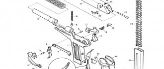
Konstantinov assault rifle
In addition to the AK-47 and the Korobov model, Konstantinov and Simonov assault rifles were also presented for testing, but unlike all the others, the OKB-180 with a Simonov assault rifle, which did not participate in comparative factory tests, first of all had to confirm the readiness of its product for testing field tests, i.e., to catch up with competitors who were one step ahead. One sample of each design of assault rifle was presented for testing in two modifications - with wooden and folding metal butts. All machine guns were equipped with bladed bayonets. The systems of Kalashnikov and Simonov worked on the principle of removing part of the powder gases through a transverse hole in the wall of a fixed barrel, and in the systems designed by Korobov and Konstantinov, the automatic action was based on the principle of recoil of a semi-free bolt with an unloaded chamber, in which there were longitudinal Revelli grooves. This scheme made it possible to achieve a smaller drift of the barrel away from the aiming line, which had a positive effect on accuracy; because of those same grooves, the initial speed compared to the AK-47 dropped by 38.5 m/s, and the rate of fire was inconsistent and the dispersion reached 185 shots per minute. The muzzle flash when firing from these two machine guns was significantly greater in size and intensity than that of the AK-47 . The length of the force was 200-250 mm versus 30-40 mm for the Kalashnikov. This was explained by the less complete explosive decomposition of gunpowder due to the use of a semi-free bolt. The pressure curve in the chamber has a lower maximum pressure, a longer time for the pressure to rise to maximum, and a longer time for the pressure to remain until the bullet leaves. But the most important thing for machine guns of this design was that the primer was inertially punctured at the moment the cartridge was removed from the magazine, and then the cartridge case was torn right in the receiver, and this property was in no way justified by better accuracy, less weight, less labor intensity, or greater cheapness. The Kalashnikov assault rifle differed little from the production model of the previous model: the weight of the weapon was reduced due to changes in its production technology. A return to the manufacture of the receiver using the stamping method, which was abandoned in 1951 in favor of milling, not only reduced its weight, but also reduced metal consumption by 80%. Some parts began to be produced using lost wax casting and powder metallurgy. The pistol grip and magazine began to be made of plastic. As a result of all these changes, the weight of the machine gun decreased by almost a kilogram. The rigidity of the receiver cover was increased by adding transverse ribs. The most important achievement was the increase in the accuracy of fire. This was achieved by introducing into the design a simple compensator, which was an oblique cut in the muzzle of the barrel. True, this element appeared only towards the end of the tests as a response to the challenge of Korobov and Konstantinov. In addition to its main purpose, the compensator also slightly lengthened the barrel and provided the bullet with an additional 5 m/s when leaving the barrel. Initially, the thread on the muzzle of the barrel was intended to install an attachment that allowed firing blank cartridges. There is also information that it was planned to screw the mortar of the Dyakonov rifle grenade launcher or VG-45 rifle grenade launchers onto this thread. There was also a small-scale 58-mm mortar for this machine gun, designed to throw RGD-5 grenades at a 150-meter distance. A device for silent shooting, PBS or PBS-1, commonly referred to as a silencer, can be installed on this thread. These installations did not go into mass production, just as the slotted compensator-flame arrester did not go into production, which seemed much more effective than a beveled compensator, and also made it possible to use captured NATO standard grenades. The reason for this lies in the fact that when using any of these attachments, the barrel of the machine gun did not fit into the embrasure of the armored personnel carrier. In addition, the improvement in accuracy was facilitated by the transfer of the bolt frame stop to the left side and the appearance of a trigger retarder in the design of the trigger mechanism, which slightly slowed down the automation cycle. Thanks to the increased accuracy of fire, the sight markings were raised to a thousand meters, although the effective firing range from a machine gun still did not exceed 400-500 m, and the median deviation of hits at an 800-meter distance was 0.64 - 0.9 meters. Instead of a bladed detachable bayonet, the machine gun was equipped with a universal bayonet-knife with a file, which was also used in conjunction with a sheath as scissors for cutting barbed wire or live fences. The blade width was 30 mm, length – 150 mm. It was this model that, by resolution of the Council of Ministers of the USSR dated April 8, 1959, was adopted by the Soviet Army under the designation AKM .
The main external differences between the AK-47 (above) and the AKM (below)
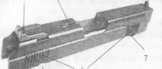
AKM device
The AKM is built using a gas exhaust engine with a long stroke of the gas piston. The gas piston rod is attached to the massive bolt frame using threads. Early AK-47 had grooves along the body, which disappeared on the AKM . The gas chamber is located above the barrel, and the gas chamber, which is attached to the bolt frame via a thread, moves inside a detachable gas tube, equipped with a barrel lining, but devoid of the holes found on the AK-47 . The AKM gas chamber lacks an eye for a cleaning rod, as well as a cutout for attaching a portable belt. Instead, it now has a stop for latching the handle of a bayonet-knife with a hole for a ramrod. The front swivel of the portable belt in the AKM was placed on the forend ring. In addition, protrusions were made in the ring to fix its position on the barrel.
Gas outlet tubes with barrel linings: on the left for AK, on the right - for AKM. The hammer-type trigger mechanism was equipped with an additionally introduced anchor-type trigger retarder. This element, proposed by designer Vasily Fedorovich Lyuty (author of the LAD machine gun), delayed the release of the trigger by several milliseconds when conducting automatic fire. The trigger, turning after the release, hit the shoulders of the retarder twice, and the time of rotation of the trigger increased so much that by the time the shot was fired, the muzzle of the barrel, as a result of vibration, managed to take a position close to that of the previous shot. USM AKM: 1 – trigger; 2 – mainspring; 3 – trigger; 4 – single fire sear, 5 – self-timer; 6 – self-timer spring, 7 – translator, 8 – axes; 9 – single fire sear spring, 10 – trigger retarder, 11 – trigger retarder spring; a – combat platoon; b – self-timer cocking; c – curved ends; g – loop; d – figured protrusion; e – rectangular protrusions; g – tail; h – cutout; and - whispered; k – lever, l – latch; m – front protrusion, n – sector; o – axle.
The AKM bolt carrier is slightly lighter than the AK-47 , but despite certain differences in shape, it can be used in conjunction with the AK-47 . The AKM barrel is installed in the socket of the barrel base and is fixed with pins (in the AK-47 it is screwed on). Additionally, on its outer surface there are longitudinal grooves for protrusions that secure the forend mount.
AKM bolt carrier : 1 - channel for the bolt; 2 - safety ledge; 3 — protrusion for lowering the self-timer lever; 4 — protrusion for bending the receiver; 5 — handle; 6 — figured cut; 7 — groove for the reflective protrusion; 8 - gas piston.
AKM gas piston unscrewed from the bolt carrier
The bolt frame moves in the receiver along two side guides, while the design of the assault rifle provides large gaps between the moving parts of the automation and the receiver, which ensures reliable operation of the automation even with very heavy contamination inside the weapon. AKM automatic operation under difficult operating conditions is ensured by a gas engine with obviously excess power, which made it possible to abandon the use of a gas regulator, thereby simplifying the design of the weapon, as well as its operation. However, these decisions also led to an increase in recoil and vibration of the machine gun when firing, reducing the accuracy and accuracy of fire, as well as reducing the service life of its receiver, against the rear wall of which the massive bolt frame hits. The barrel bore is locked by turning the bolt onto two lugs, which engage with the elements of the liner on the receiver. The rotation of the bolt is carried out by the interaction of its protrusion with a shaped groove located on the inside of the bolt frame. The guide rod, its base and the return spring are made in a single assembly. The base of the guide rod serves as a latch for the receiver cover.
the AKM assault rifle is made by stamping from a sheet of steel with a milled insert riveted in its front part. For early AK-47 assault rifles, the receiver was made from a combination of milled and stamped elements, while for serial ones it was completely milled. Milled and stamped receivers differ externally in the shape of the recesses located above the magazine well. AK-47 box there are long rectangular recesses, and on an AKM there are small oval stampings. The bolt cocking handle is located on the right side of the receiver, is made of a single part with the bolt frame and moves with it when firing. The fire mode switch fuse is made in the form of a long stamped lever located on the right side of the receiver and has 3 positions: the top one is “fuse” and the bottom one is “single fire”. Being in the top position (“safety”), the translator closes the slot on the receiver, preventing dust and dirt from getting inside the weapon, blocks the rear movement of the bolt frame, and also blocks the trigger. On the AKM, the ridge of the butt was raised upward, ensuring a reduction in the “tossing” of the machine gun when firing, and for serial AKMs the pistol grip began to be made of plastic. Additional cavities were made inside the butt in order to reduce its mass.
Lightweight gen 2 frame
Product data sheet: Lightweight bolt carrier. (cal. 5.45; 223; 7.62 / ART #LAC0999)
Hello ! Thank you for choosing our product! Best regards, LAC Team
1. Purpose:
The lightweight bolt carrier serves to reduce recoil and the overall weight of carbines and assault rifles based on the AK74, AK74M, RPK74, RPK74M, AK 100 (103,104,105), AK200 and civilian models based on them: Saiga 030, 033, TG2, TR3, VPO 219, 222 , 1B including and cal. 366TKM, as well as analogues with a bolt shank diameter of 9 mm.
2. Kit:
- Frame body - 1 piece
- Titanium rod with collet fastening or Titanium rod for pinning - 1 pc.
- Screw (complete for rod with collet), strength class 12.9, M5*16 — 1 pc.
- Left cocking handle with notch - 1 piece
- Handle screw M6*40 DIN 912 (strength class 12.9) equipped with M6 nut - 1 pc.
3. Assembly:
Screw the rod into the frame using an open-end wrench with a 10mm gap along the flats for the key and fix it with a counterscrew through the return spring channel in the frame.
Insert the left handle screw into the corresponding hole in the frame.
Hold the handle and tighten the screw using a 5mm hex key. Tightening should be done until 1-3 turns of screw thread emerge above the thickness of the nut, with control of the visible passage of the screw through the nut ring.
Before use, lubricate the frame and its elements with neutral gun oil or powder lubricants.
4.Adjustment:
Set the rod to a position where its length will be 5 mm less than the length of the rod of the standard frame of a particular carbine. Secure the rod using a counter screw.
Do not over-tighten the counter screw! The position of the rod is not final!
Test shooting to determine the functionality of the carbine's automatics. If the result is positive, you should continue screwing the rod into the frame body until the most acceptable result is obtained. The automation must operate stably with a guaranteed ejection of the cartridge case 2-3 meters from the shooter, in any spatial position of the weapon, as well as at subzero temperatures. If the automatic operation cycle is not complete without extraction of the cartridge case, the rod should be unscrewed, increasing its visible length.
After receiving data on the required length of the rod on a specific specimen, you should write it down, unscrew the rod, cover the external thread of the rod with red thread lock, cover the threads of the counterscrew with red thread lock and assemble, set the rod overhang according to the recorded value, do not use for 24 hours.
5. Using the frame in auto-fire mode:
The frame has a full-fledged self-timer tide, so it can be used in automatic fire machines.
In this case, the use of red thread sealant is mandatory!
To avoid unwinding of structural elements, inspection should be carried out every 500 shots. If the frame is used in machine guns with high-capacity magazines (more than 70 rounds), the rod should be pinned through the existing hole in the frame rod, according to the AK74 Repair Manual. When drilling the frame, use carbide drills made from VK8 alloys or analogues.
6. Use with RGB:
When using a lightweight frame in conjunction with an adjustable gas block, the effect of reducing and softening recoil is increased, and adjustment and cleaning are greatly simplified. In the case of joint use of devices, the frame rod should be installed 5 mm shorter than the standard weapon frame rod and fixed in accordance with paragraph 4, adjustment should be made with a gas block.
7. Warranties and limitations when following the above recommendations:
- Due to the increased friction of titanium and steel, abrasions may appear on the head of the frame rod - this is not a defect, and no deterioration in performance has been detected.
- The frame rod and the left cocking handle are consumable items and in the event of failure or breakage, they are replaced by the user independently; the warranty does not apply to these items. To replace the left handle screw (if it is broken due to its absence in the original frame design), you should use a screw of the following nomenclature: Screw M6*40 DIN 912 (strength class 12.9, 10.9, 8.5 strength in descending order) complete with an M6 nut.
- The frame body is a warranty item and is replaced in case of detected defects. Claims should be sent to: [email protected]
- Independently making mechanical changes to the structure of the frame body (with the exception of pinning the rod, replacing the rod and left handle) will void the warranty. In this case, the frame body will not be replaced and the claim will be denied!
- You can ask questions by writing an email to: [email protected]
Frame body:
- Weight – 262+/- 2 g
- Material: hardened steel
Left handle assembly:
- Weight - 19.6 g
- Screw material: hardened steel
- Handle body material - alloy D16T
Stock:
- Assembled weight - 43.5 g
- Rod length - 155 mm
- Rod material: titanium
- Screw material: hardened steel
AKM ballistic data
Firing range, m
| Final bullet speed, m/s | Flight time of the bullet, s | Bullet energy, kgm | |
| 0 | 715 | 0 | 207 |
| 100 | 623 | 0,15 | 157 |
| 200 | 537 | 0,32 | 117 |
| 300 | 459 | 0,52 | 86 |
| 400 | 391 | 0,76 | 63 |
| 500 | 334 | 1,04 | 47 |
| 600 | 304 | 1,35 | 37 |
| 700 | 284 | 1,69 | 32 |
| 800 | 266 | 2,05 | 29 |
| 900 | 250 | 2,43 | 26 |
| 1000 | 235 | 2,84 | 23 |
| 1100 | 220 | 3,27 | 19,5 |
| 1200 | 206 | 3,74 | 17,1 |
AKMS
A modification of the AKMS for the Airborne Forces had a folding stock made of stamped steel profile. Such a butt was folded down and forward in such a way that the back part of the butt was “laid” under the forend of the machine gun. Accessories for these machines were stored separately. The wooden pistol grip lasted longer on the AKMS than on the AKM - the original plastic grips, unprotected from mechanical influences when the butt was folded, did not have sufficient service strength. The landing version of the assault rifle - AKMS - has a steel folding butt, which is structurally different from the AKS-47 butt by the presence of recesses and rivets.
PKK
RPK light machine gun was adopted by the Soviet army in 1961. The design of the RPK is almost similar to that of an assault rifle; most of its components and parts are interchangeable. The main differences are the elongated heavy barrel and the presence of a folding bipod. The 590 mm long barrel made it possible to increase the effective firing range to 800 m. Increasing the thickness of its walls made it possible to conduct more intense fire. The bipod has improved accuracy when shooting from a rest position. To increase the combat rate of fire, the capacity of the sector magazine was increased to 40 rounds. A disk magazine was also developed, which is now called a tambourine. Its capacity was 75 rounds. For ease of shooting from a machine gun, the butt was made in the shape of the RPD , and to take into account the influence of external conditions on shooting accuracy, the RPK was equipped with a moving whole with a lateral correction mechanism. With the replacement of the SKS-45 carbines with the modernized AKM assault rifle, and the RPD with the RPK, automatic weapons in the squad-platoon link became completely unified in terms of cartridge and system. The widespread unification of components and parts of a light machine gun with the already mastered AKM greatly simplified the production of the RPK and its study among the troops.
CHAPTER 9 Modernization of AK
CHAPTER 9 Modernization of AK
Despite the successes, Soviet gunsmiths did not rest on their laurels. The modification of the machine based on operational comments in production conditions was carried out by a team of authors with the wide involvement of designers and technologists from the Izhevsk Machine-Building Plant. The main directions of design refinement of the Kalashnikov assault rifle were determined by both the Ministry of Armaments and the GAU of the Ministry of the Armed Forces of the USSR. The most direct participation in this work was taken by the designers and engineers of the Klimovsky Research Institute-61 S.S. Rozanov, and from the Armed Forces - representatives of the Small Arms Directorate of the GAU I.Ya. Letichevsky, I.N. — Piskun, V.S. Deykin, V.I. Algalov, I.P. Bushinsky. Moreover, BC Deikin again helped his mentee at the training ground M.T. Kalashnikov, providing constant assistance to the plant and design team in the process of improving the AK.
The main directions in further work on the modernization of the Kalashnikov assault rifle in the early fifties were increasing the survivability of parts and improving its performance characteristics, achieving reliability of the automation, and improving the combat properties of the weapon. Moreover, the mass production of new weapons required a significant reduction in the financial costs of its production, and this could be done by reducing the mass of the sample and reducing the labor intensity of production. Thus, the total metal consumption for the manufacture of one machine gun was 15 kg. with a total mass of finished parts of approximately 3.5 kg, which was a lot.
Soon Mikhail Timofeevich began developing a new AK model. All the efforts of our gunsmiths were aimed at maximizing the weight of the machine gun while maintaining its high combat and performance qualities. First of all, the search was carried out to replace the acutely shortage of high-alloy steel 25ХНВА, from which a large number of parts of the AK assault rifle were made. and transfer of its production to cheaper steel grades. After a series of works, the optimal solution was found, and nine parts of the Kalashnikov assault rifle, including the trigger, as well as the most metal-intensive bolt group, were transferred to cheap high-strength low-alloy steel 30XPA. A significant reduction in weight (0.5 kg) to 3.8 kg was achieved by lightening the milled receiver, reducing the thickness of the receiver cover, and using a new magazine. The survivability of the striker was increased with plane-parallel edges of the rod part, which, unlike the standard striker, did not have an annular thickening at the rear thorn. The magazine, made not from steel sheet (weight without cartridges - 0.43 kg), but from light alloys (weight without cartridges - 0.33 kg, weight with cartridges - 0.82 kg), has also undergone fundamental changes. To increase its reliability and protect the feeder spring from deformation during operation, the side walls of the magazine body were reinforced with stiffeners.
One of the interesting pages in the long life of the Kalashnikov assault rifle is the adoption of a bayonet for it.
7.62 mm lightweight Kalashnikov AK assault rifle with a second shaped 6×2 knife.
7.62 mm lightweight Kalashnikov AK assault rifle with a lightweight folding bipod. Prototype.
The established traditions of the Russian army, most clearly expressed in the apt aphorism of A.V. Suvorov: - The bullet is a fool, the bayonet is a good fellow - they were revered in the Soviet Armed Forces. The GAU leadership fully shared the opinion of the famous military theorist and teacher General M.I. Dragomirova: “No matter how perfect the gun is, even by 50 steps a miss is more likely than with a bayonet by a step or one and a half; and in any case, the latter requires much more fearlessness, self-sacrifice, and a sense of camaraderie to act than shooting, which is more in keeping with the instinct of self-preservation. Shooting requires rest, a strike with a bayonet requires forward movement, which in itself expresses the feeling of our superiority over the enemy. You can exchange fire for hours and achieve nothing; the bayonet immediately forces the enemy to give up the rear.” In this regard, after a series of development work, NIPSVO concluded that: “in modern conditions, the bayonet is still a material representative of the highest tension of the will to win, so the machine gun should also have a bayonet” to improve use weapons in hand-to-hand combat, a detachable blade bayonet of the 2nd model (6 × 2 product) is used with a machine gun with a wooden butt. The bayonet could also be used as a knife.
A ring was mounted on the handle, with which the bayonet was put on the barrel coupling, as well as protrusions for mounting on the gas chamber. The bayonet was fixed with a latch with a spring on the ramrod stop. In the traveling position, the bayonet was worn on a waist belt in a metal sheath. The mass of the 2nd sample bayonet with scabbard is 0.37 kg. Since such a fight required special physical, technical and psychological training of personnel, the troops again began to master hand-to-hand combat using a bayonet and butt.
While working on his machine gun, M.T. Kalashnikov tried to improve his weapons by increasing combat characteristics, especially accuracy when firing automatic fire. A similar desire came to life in the early 1950s. the emergence of several models of experimental machines. They tried to achieve stabilization of the weapon during shooting through the use of various designs of additional stops, since studies showed that the use of a bipod on Kalashnikov assault rifles increases the accuracy of fire by 1.5–2 times. First, a prototype of the 1950 AK assault rifle with a folding one-legged bipod-rest for shooting in a prone position appeared. The bipod-rest was attached to the muzzle of the barrel. In the stowed position, it folded under the forend.
7.62-mm lightweight Kalashnikov AK-47 assault rifle with an additional support-handle on the fore-end. Prototype.
7.62-mm lightweight Kalashnikov AK assault rifle with an unfolded bipod-rest. Prototype.
7.62 mm lightweight Kalashnikov AK. Issue 1954–1957
It was replaced by another model of the Kalashnikov assault rifle with an additional wooden pistol grip placed under the fore-end, into which a telescopic metal one-legged bipod was mounted, which also served as an additional support for the weapon when shooting prone. In 1953, two more variants of the assault rifle appeared - AK and AKS. equipped with lightweight quick-release bipod wire bipods mounted on the muzzle of the barrel. In the stowed position, the bipod was folded onto the sides of the forend and secured with slides on the sides of the sight block. The skids were stamped metal plates curved on the sides, which served to rest on the ground when firing. However, the main obstacle to the adoption of the bipod was the fact that when shooting from unstable positions (kneeling, standing, on the move, etc.), its not entirely successful design negatively affected the handling of the weapon, limiting its fire maneuverability, creating additional inconvenience during combat in trenches, trenches, etc. Therefore, the designers’ work never went beyond the prototypes.
Based on proposals from the troops and the “Vystrel” courses, the upper swivel in the Kalashnikov assault rifle was moved from the fore-end ring closer to the muzzle of the barrel - to the gas chamber, which eliminated the loosening of the fore-end during operation of the assault rifle. The wooden parts of the machine again underwent major alterations. The reduction in the cost of their production was facilitated not only by the new technology for the production of the butt and forearm, where birch blanks were replaced with slabs of birch plywood, and the barrel linings were now made by stamping from glued veneer, but also by a simpler attachment of the butt. Instead of the butt clip used in the previous model, a butt plate with two shanks was again used, but which was now attached to the receiver not with rivets (as in the first model of the serial AK produced in 1949), but by washing. This design ensured not only a reduction in manufacturing costs, but also made the weapon itself more durable in hand-to-hand combat. Along with this, returning to the old proven scheme of attaching the butt to the receiver eliminated the loosening of the butt clip, which greatly influenced the improvement of the accuracy of the Kalashnikov assault rifle, making it more stable during shooting. The dispersion when firing from an AK in short bursts at a direct shot range (350 m) at a chest figure 50 cm high began to be 0.3x0.4 m, which was a good result for such a weapon, although effective shooting at a maximum range of 800 m due to the large bullet dispersion (1.9–2.7 m) was practically impossible. AKS assault rifles have a limiter on the shoulder rest of the metal butt, intended to protect the forend from damage by the rest when folded. At the same time, the reliability of the automation was significantly improved, which was achieved both by reducing the energy losses of the sliding parts to overcome friction forces caused by various distortions of the parts, their unfavorable dimensions, and by improving the parameters of the gas exhaust system, etc. in particular, by the diameter of the gas outlet hole, the radial piston clearance and the piston volume of the gas chamber.
Bolt frame with bolt of a 7.62 mm lightweight Kalashnikov AK assault rifle. Issue 1954–1957
7.62 mm Kalashnikov AKM assault rifle with a 6x2 bayonet in a sheath. Issue 1953–1957
As a result of extensive work to modernize the Kalashnikov assault rifle, both its design and production technology were improved. This led to a significant increase in the combat and service-operational qualities of the weapon, since the AK. Possessing a rational automation design with promising reserves, it had great opportunities for further structural and technological improvement. The reduction in the labor intensity of production by 1954 led to a decrease in metal consumption by 1.2 kg, and in addition to a sharp, almost threefold, reduction in its cost - from 2002 to 676 rubles. An improved version of the weapon entered service with the Soviet Army already in 1954 under the designation “Lightweight 7.62 mm Kalashnikov assault rifle (AK).” and already in the next year, 1955, the Izhevsk Machine-Building Plant mastered the production of the third model of the Kalashnikov assault rifle (index 56-A-212) with a wooden butt and AKS with a folding butt (index 56-A-212M). The weight of the machine gun decreased by 0.5 kg (from 4.3 to 3.8 kg), and the total weight of the weapon with portable ammunition (180 rounds) decreased from 10.1 to 9.1 kg (the weight of the machine gun with a loaded magazine is 4. 3 kg). The main, and not eliminated, disadvantage of this machine gun remained low accuracy when firing continuous fire.
In carrying out work to improve the machine gun in the production hall, as well as in the creation of modernized AK samples, a significant role, in addition to M.T. Kalashnikov, was also played by a special group (which grew into a single design bureau in 1954), consisting of design engineers: V.V. Krupina, A.D. Kryakushina, V.I. Pushchina, design technician F.V. Beloglazova, copyist V.A. Zinovieva, mechanics: G1.P. Bukharina, E.V. Bogdanov, milling operator G.G. Gabdrakhmanova; turner A.N. Berdyshev, spoon maker P.M. Permyakova. Along with them, a large part in the modernization of the Kalashnikov assault rifle was taken by both specialists from the Izhevsk Machine-Building Plant and representatives of the customer - the Ministry of Defense, as well as the Ministry of Defense Industry: V.P. Boltushkin, T.G. Levin, V.A. Kharkiv. N.F. Kulichkov, L.M. Okhotnikov, A.F. Markov and many others.
Sight NSP-2: a - general view, b - section 1 - aperture; 2 — electro-optical device: 3 — infrared spotlight: 4 — sight body; 5 - high-voltage converter: 6 - battery 3SC-25: 7 - battery case with low-voltage converter.
Along with modernizing the Kalashnikov assault rifle, designers tried to expand its potential capabilities. Already in 1954-55. new variants of the AKN/AKSN assault rifle have appeared with the possibility of installing NSP-2 illuminated night shooting sights on them, which will allow you to detect targets at night or at dusk and conduct targeted shooting at ranges from 150 to 250 m (depending on weather conditions and time of year). The sight magnification is 2.1x. The sight consisted of a sight body. electron-optical voltage converter and battery ZSTs-25 in a case. The electro-optical device and the high-voltage converter were mounted in the sight body, and the battery and low-voltage converter were mounted in the case. The NSP-2 sight is powered by an infrared spotlight with a 25 W lamp-headlight. used to illuminate the target, was powered by a rechargeable battery carried in a bag on the shooter’s waist belt. The centerline of the light was 40,000 candles, and the scattering angle was 6°. To mount the sights on the machine gun, the base of the dovetail bracket, which fits into the groove of the sight body bracket, was secured with screws on the left side of the receiver. The design of the sight assumed the use of such a weapon for shooting from any position, both from a standstill and during short stops when operating on foot, including lying down from the hand, from the knee, and standing. However, taking into account the significant mass of the sight (the total weight of the machine gun and NSP-2 is 8.18 kg; the weight of the sight with the bag is 4.9 kg), the most effective was shooting while lying down or from the knee using various objects as a support.
7.62 mm Kalashnikov AKN assault rifle with NSP-2 night sight.
7.62-mm Kalashnikov AKMSN assault rifle with NSP-2 night sight.
In the mid-1950s. in the Soviet Union on the initiative of the USSR Minister of Defense G.K. Zhukov created reconnaissance and sabotage units and special purpose units of the GRU PN of the Soviet Army. The tasks facing these units also required appropriate equipment of the reconnaissance officers with special weapons that would not only have high shooting efficiency, but also the ability to use them covertly. Therefore, already in 1956, the troops received another, very successful modification of the Kalashnikov assault rifle with a device for silent and flameless shooting (IVS) designed by NII-61 engineer L.I. Golubeva. In a device for silent and flameless shooting of the expansion type, sound suppression was achieved not only by reducing the pressure of the powder gases at the muzzle, but also by using cartridges with subsonic bullet speed. Shooting from this shot silencer was carried out with special “UO” cartridges with a reduced initial bullet speed (270–295 m/s), created by the engineer of the same research institute G.M. Tereshin under the leadership of the head of the ammunition department B.V. Semina. The heavier bullet of the new US cartridge of a modified design had a steel core in the head.
Night sight NSP-2 on a 7.62 mm Kalashnikov AKMSN assault rifle.
7.62×39 automatic cartridge model 1943 with reduced bullet speed US: a - cartridge, b - bullet; 1 - shell; 2 - steel core; 3 - lead core. The UO bullet with a steel core ensured penetration of a steel helmet at ranges up to 400 m. The tip of the bullet was painted black and green. Bullet weight -12.5 g.
The PBS device was mounted on the muzzle of the barrel with a threaded fit. The PBS body consisted of two semi-cylinders connected to each other at the rear and two axles. On the outer surface of the semi-cylinders there was a thread for connecting the body with the head, which was screwed onto the barrel. To prevent the body from unscrewing itself, a latch in the form of a leaf spring was riveted to one of the half-cylinders. In the cavity of each half-cylinder there were 12 partitions with semicircular cutouts for the passage of a bullet, and in the first partition a seal was attached, which was a rubber stopper enclosed in a metal clip with a latch. For firing from an AK assault rifle with PBS, a special aiming bar with the possibility of lateral shifting of the rear sight was also used. On the upper plane of the bar there were divisions with numbers from 1 to 10 and a division with the letter “P” for firing ordinary cartridges. And on the back side of the bar (on the lower plane) divisions with numbers from 1 to 4 were applied for firing with “US” cartridges. When fired, the bullet, as it left the barrel bore, pierced the rubber seal, which, compressing, slowed down the flow of powder gases into the body of the device. The gases that managed to break through after the zeros into the compartments formed by the partitions, expanding, lost speed without causing sound. The shutter ensured reliable operation of the machine's mechanisms until 200 rounds were fired, and after that it was subject to replacement. An AK assault rifle with a PBS device made it possible to conduct targeted actual fire at ranges of up to 400 m. In night conditions, targeted shooting from an AK with a PBS could be carried out with a set of NSP-2 night rifle sights.
The appearance of such a simple, but at the same time extremely effective weapon, such as the AK with PBS in the arsenal of reconnaissance units and special forces units, made it possible to bring Soviet special weapons forward, since our opponents at that time did not yet have standard silent automatic small arms, designed for a powerful “intermediate” cartridge.
7.62-mm lightweight Kalashnikov AK-47 assault rifle with a device for silent and flameless LAN firing.
A device for silent and flameless firing of IVS.
Disassembled device for silent and flameless firing of IVS (split into two parts)
SVK
In addition to the AKM and RPK, Kalashnikov also developed a sniper rifle, designated SVK. The Kalashnikov sniper rifle was created in two versions. The first sample had a buttstock with a semi-pistol neck and a cheek piece on its left side. The barrel lining completely hid the gas mechanism of the rifle. The second version of the rifle was created for the purpose of maximum unification with the Kalashnikov assault rifle currently in service. It had a similar AK stock, pistol grip fire control and forend. The design of the receiver and receiver cover, as well as the safety lever and open sights, also repeated the details of the famous machine gun. The rifle was actually an enlarged Kalashnikov assault rifle, modified for a more powerful 7.62x54 mm R cartridge, with a trigger that allowed only single fire. The firing mode switch fuse is located on the right side of the receiver. Food comes from a replaceable sector-shaped box magazine with a capacity of 10 rounds. The short receiver cover and grooves in the front of the bolt frame made it possible to equip an attached magazine from a clip. On the left side of the receiver there is a bracket for mounting an optical sight. The 1959 Kalashnikov rifle had a split stock, which included a wooden butt, fore-end and receiver lining. However, unlike the machine gun and machine gun, the sniper rifle lost in the competition to the Dragunov system.
See also:
Operating principles, locking methods and bolt mechanisms of automatic weapons
OPERATING PRINCIPLES
In modern small arms, the general principle of operation of the mechanisms can be described as follows: releasing the latch and separating the bolt from the barrel;
further movement of the bolt back while simultaneously removing the cartridge case from the chamber and ejecting it from the weapon (in this case, the bolt is retracted to its final position and engages the firing mechanism); forward movement of the bolt under the action of the return spring with simultaneous capture of the next cartridge and feeding it into the chamber: locking the barrel with the bolt and capturing the cartridge with the cartridge ejector; releasing the impact mechanism using the trigger device (in this case, the firing pin hits the primer and ignites the flammable substance); shot. Then the whole cycle repeats.
The operating principle presented here in a simplified form is typical for all types of small arms. But there are still significant differences in the locking methods, the operation of individual mechanisms and the principles of operation of the automation. Based on the degree of automation, small arms are divided into automatic and non-automatic weapons. When using a non-automatic weapon, the shooter must perform the operations described above manually. In automatic weapons, this is done using the energy of the powder gases released when fired.
All automatic weapons are divided into two groups according to the method of using the energy of powder gases: weapons in which automatic action is achieved by using the recoil energy that occurs during a shot; weapons in which the automation is driven by the pressure of powder gases.
AUTOMATIC WEAPONS POWERED BY RECOIL ENERGY
This group includes both weapons where the recoil energy acts directly on the bolt, thereby activating the automation, and weapons where the automation mechanisms are connected to a movable barrel.
WEAPONS USING THE RECOIL OF THE SHUTTER
In such weapons, the barrel is rigidly connected to the body. In this case, a distinction is made between a weapon with a blowback and a weapon with a semi-free (inhibited) bolt. In a weapon with a blowback, the latter is not connected to the barrel when firing, but is only pressed against it using a return spring. In order for this system with very simple automation to function reliably, a fairly massive bolt and a cartridge with a short sleeve are needed, and the pressure of the powder gases when using such a cartridge must be relatively small so that it becomes possible to use shorter bolt systems.
As soon as the gas pressure in the barrel rises during a shot, the bolt begins to roll back along with the cartridge case. During the time that the bullet passes along the barrel, the bolt moves only 1-2 mm at a speed of 4 to 6 m/s. This initial impulse is enough to push the bolt to its rearmost position even after the bullet has left the barrel. This compresses the return spring, which again returns the bolt to the forward position. At this time, the next cartridge enters the chamber from the magazine, which ignites when interacting with the trigger system.
Weapons with a semi-free (inhibited) bolt operate on the same principle, but the bolt in it has less mass and is connected to the body by a moving element, which reduces its speed. Semi-blowbacks are sometimes used in cases where the rate of fire of a given weapon, according to technical requirements, should not be high.
In weapons with both types of bolts, the use of rifle cartridges is not recommended, since in this case, due to the increased pressure of the threshold gases, the bolt speed becomes too high.
WEAPONS USING RECOIL
Movable barrel designs include long-stroke weapons and short-stroke weapons.
In long-stroke weapons, the barrel and bolt are connected to each other before firing and are held in the forward position under the action of a recoil spring. After the shot, the barrel and bolt, first under the pressure of the powder gases, and then under the influence of inertia, slide back and at the same time compress the return spring. After hitting the rear wall and sliding slightly forward, the bolt, held by the trigger, is secured in the rear position. The barrel, under the action of the return spring, returns to the forward position, while the cartridge case is removed from the chamber with the help of an ejector and ejected from the weapon. The bolt moves forward, chambers the next cartridge and locks the barrel. The gun is ready for the next shot.
Systems with a long barrel stroke are characterized by a low rate of fire. The reasons for this are the relatively large mass of moving parts and the alternate forward movement of the barrel and bolt. The movement of heavy parts, as well as impacts when they are fixed in the front and rear positions, cause significant vibrations of the weapon, which negatively affects the shooting density, so such designs are used quite rarely.
In weapons with a short barrel stroke, the bolt is unlocked after only a short movement of the barrel. In order to sufficiently speed up the movement of the bolt after unlocking the barrel, so-called accelerators are built into the mechanism.
The automation in such weapons works extremely reliably and provides a high rate of fire with low recoil. For this reason, this design is widely used in heavy and heavy machine guns.
WEAPONS USING THE ENERGY OF POWDER GASES REDUCED THROUGH A HOLE IN THE BARREL WALL
Small arms of this system have a hole drilled in the barrel wall (gas hole). When a bullet passes through a gas hole in the barrel, part of the powder gases enters the gas chamber through it and presses on the end surface of the gas piston, which moves back and acts on the bolt guide mechanism.
After a short free movement of the guide mechanism by 3-6 mm, it unlocks the bolt and moves it to the rear position. This ejects the spent cartridge case and compresses the return spring. From the rearmost position, the bolt, under the action of the return spring, begins to move forward, captures the next cartridge, feeds it into the chamber and locks the barrel. Mechanisms of this type may have the following design differences:
- a system with a fixed connection between the gas piston and the valve guide mechanism (long piston stroke);
- system with a free connection (short piston stroke):
- system without gas piston.
The most widely used systems are those with long piston strokes. Some machine guns and automatic rifles, as well as almost all modern machine guns, operate on this principle.
If it is necessary to load a weapon with a clip, then use a loose connection between the bolt guide mechanism and the gas piston. In devices with a short piston stroke, the gas piston, using a pusher, transfers kinetic energy to the guide mechanism, and then, under the influence of the pusher spring, returns to its original position. In this case, the gas piston moves only within a small segment.
In a device without a gas piston, powder gases through a thin gas hole act directly on the base of the bolt, which then moves backward and activates the automatic mechanism. Weapons of this type are characterized by simplicity of design and the ability to regulate the gas pressure acting on the moving parts. Many types of small arms are designed according to this principle.
2. LOCKING METHODS
Locking the barrel refers to the process of connecting and bolting before firing. In general, the locking mechanism includes the barrel, bolt and body. During a shot, these parts are subjected to high dynamic loads and high temperatures.
The following locking methods are used in small arms, depending on the corresponding design:
- shutter misalignment,
- rotating shutter,
- rotating bolt head or coupling,
- combat protrusions,
- using a wedge (key),
- roller shutter.
The smallest group of locking parts is used when using a rotating bolt, rotating head or bolt clutch. Structurally, locking by rotating the bolt or bolt head is the most acceptable. Therefore, this locking method is used in many types of weapons. Also, when using safety valves, the time intervals between closings are quite long. But since the safety valve breech is a relatively simple design, modern weapons are often equipped with this type of breech.
DEVICES FOR LOCKING AND UNLOCKING THE SHUTTER
With the help of these devices, the bolt and barrel are connected before the shot and are separated again after it. Locking and unlocking of the bolt is carried out in very short periods of time, at high speeds of movement of the parts of the bolt and under the pressure of powder gases, so the friction between the individual moving parts is quite high. To reduce their wear, special technical measures are used.
Devices for locking and unlocking the bolt are a special group of automatic weapon mechanisms. In the book, we consider in detail only the most common designs, in which the sliding movement of the bolt in the direction of the main axis is used to lock and unlock the barrel hole.
Depending on the type of unlocking (locking), these devices are divided into:
— devices with a self-opening shutter;
— devices with partially forced unlocking;
— devices with forced unlocking.
Devices with a self-opening bolt include designs in which powder gases act on the base of the cartridge case and the bolt, and the automation of which operates on the principle of a braked bolt. In such systems, unlocking and locking are inhibited during the period of maximum pressure of powder gases.
Thus, the kinetic energy of the bolt decreases as it moves to the rear position. The release of the cartridge case from the chamber slows down during the period of maximum pressure of the powder gases. This prevents the sleeve from bursting. Self-opening bolts facilitate the creation of simple weapon designs and allow the use of powerful cartridges for which a blowback bolt is unsuitable.
In the case of partially forced locking, the pressure of the powder gases is also transferred to the bolt, but the unlocking of the bolt during the maximum pressure of the propellant gases is limited by the movement of the automatic parts. This slows down the movement of the bolt relative to the barrel, and also reduces the speed at which the cartridge case is removed. Due to the complexity of the design, such unlocking systems are practically not used.
In modern automatic small arms, forced unlocking systems are most often used. The shutter is unlocked here by using the kinetic energy of the moving parts of the automation. There are systems with early and late unlocking of the shutter. Early release is completed at a stage when the gas pressure in the barrel is still relatively high. It acts on the bolt through the sleeve and is used for automatic operation. During early unlocking, a significant portion of the kinetic energy is transferred directly to the gate. This reduces the force acting on the links of the mechanisms. In this regard, early release is a more acceptable design option. In addition, a high rate of fire is achieved, due to the higher speed of movement of individual parts of the automation. On the other hand, the high extraction rate of cartridges in these systems makes it impossible to use more powerful cartridges and requires a number of special technical measures to reduce the force with which cartridges are ejected. In addition, during early unlocking, the possibility of rupture of the cartridges should be taken into account. Such disadvantages significantly reduce the range of application of this type of design. But despite this, it is used especially in rapid-fire weapons, where a more complex design is accepted in the interests of a high rate of fire.
Late unlocking occurs at a relatively low gas pressure in the barrel, which has virtually no significance for the functioning of the automation, and kinetic energy is transferred to the bolt either through a gas piston or through an accelerating device (a system with a short recoil of the barrel). In general, this creates large forces in the links of the mechanism, which has a negative impact both on the durability of the parts and on the shooting density.
Devices with forced unlocking include: devices with wedge locking; devices with locking by tilting the shutter; devices with locking lugs or a lever; devices with a rotating handle shaft; devices with a rotating bolt or barrel;
devices with a rotating valve head or coupling.
When locking with a wedge, using inclined positions of the bolt or barrel, lever or rotating handle rod, a long period of time is required (depending on the design) between locking. The consequence of this may be plastic deformation of parts or rupture of the cartridge case when fired. Therefore, such locking devices, despite the downtime of their design, are used less and less. When locking with an inclined position of the barrel, the influence of a large frictional force is inevitable, which leads to increased wear and inhibition of the movement of the sliding parts. To soften shocks occurring in the mechanism parts and reduce their wear, some types of weapons use special shock absorbers (springs or plastic gaskets).
Probably the most acceptable forced locking device at present is the rotating bolt used in Kalashnikov small arms. Devices of this type, very simple in design and highly reliable, make it possible to lock at short intervals and are especially suitable for use in gas-charged weapons. Automatic small arms with a short recoil barrel are mainly equipped with bolts with a rotating head or clutch.
3. SHUTTER MECHANISMS
Among the many types of shutter mechanisms, depending on the type of shutter movement, the following can be distinguished: mechanisms with a sliding (cylindrical) shutter;
rotating bolt mechanisms; mechanisms with a sliding barrel.
ROLL VALVE MECHANISMS
Most often, small arms are equipped with just such mechanisms. Unlocking and locking of the barrel occurs when the bolt moves back and forth along the axis of the barrel. The movement of the shutter is often used to drive all the main mechanisms and devices of the weapon. For this reason, the bolt is often called the moving part of the weapon's automation.
Mechanisms for locking and unlocking the barrel channel with a sliding (cylindrical) bolt
To ensure uniform operation of all mechanisms of weapon devices, the movement of the bolt when locking and unlocking the barrel channel should be as uniform as possible, without significant acceleration. When loading, the sliding bolt travels a relatively long return path in a short period of time. But if the mass of the shutter and its acceleration are relatively large, then the parts of the shutter are subject to too large dynamic loads (impacts). Therefore, the bolt should be as light as possible, and the distance it travels when unlocking and locking the barrel channel should be as short as possible. The shorter the distance, the more uniformly the weapon’s automation operates.
When the shutter moves, a frictional force inevitably acts on its surface to a greater or lesser extent, therefore the contacting surfaces must be designed in such a way that the friction force remains small and does not increase due to dust and grease, and the shutter, when moving, receives kinetic energy that significantly exceeds friction force.
Another very important component is the time factor. Locking or unlocking the barrel with the bolt requires most of the time allocated for the automatic firing cycle. Therefore, the movement of the shutter must be precisely coordinated with the required rate of fire.
ROCKING SHUTTER MECHANISMS
In this device, the barrel channel is locked and unlocked using a bolt that swings around an axis perpendicular to the barrel channel. A shutter of this type has a very short stroke and slight acceleration with a more uniform movement, but its kinetic energy is not enough to ensure the operation of other mechanisms and automation devices. This requires additional moving elements, for example a movable barrel, which leads to a more complex design. For this reason, automatic weapons of considerable caliber are rarely equipped with a bolt of this type.
MECHANISMS WITH SLIDING BARREL
If a weapon uses a barrel as the main moving element, then the bolt can be abandoned altogether, which significantly reduces the size of the weapon. However, when the barrel moves, due to its large mass, strong shocks occur during shooting, which negatively affect the shooting density. These shortcomings have significantly limited the use of mechanisms of this type.
In modern small arms, combined mechanisms are widely used, where a sliding barrel is used in conjunction with a moving bolt.
In general, the designs of bolt mechanisms are selected depending on the operating principle of the weapon. In gas charging devices, the energy of the powder gases acts through the gas piston directly on the bolt guide mechanism, thus transferring part of the resulting kinetic energy to it. In devices using recoil energy, powder gases act directly on the bolt through the cartridge case. In automatic weapons with a sliding barrel, the operation of the mechanisms is carried out using its kinetic energy obtained during recoil.
Wollert G., Liedschun R., Copenhagen W.