Locking mechanisms in pistols
Basic concepts and requirements for pistols
The bolt is the entire mechanism designed to lock the barrel when firing a pistol. A locking unit is a set of weapon parts that ensure that the cartridge case is held in the chamber of the barrel at the moment of firing. The part that directly covers the bore from the breech is called the bolt frame.
The process of engaging the bolt frame with the receiver is called locking the bolt, and the process of disengaging is called unlocking the bolt. The following requirements are imposed on locking units and their parts: the parts must be strong enough; the details of the locking unit must provide the necessary rigidity so that the amount of elastic deformation does not exceed a specified value; the locking unit should not allow breakthrough of powder gases; the bolt must ensure uninterrupted operation of the weapon associated with reloading; the engagement of the bolt with the receiver must be symmetrical; the shutter should, if possible, have a smaller size.
Types of bolts in pistols
Depending on the design of the pistol, the nature and direction of movement, the bolts are: sliding; swinging; wedge; inertial. Pistols use sliding and inertial. Sliding bolts include those whose movement before engagement with the receiver and after disengagement occurs in the direction of the axis of the barrel bore. Inertial bolts (free) do not engage with the barrel. In this case, the bolt is pressed against the edge of the barrel by spring force. Reliability of locking is primarily achieved by the large mass of the bolt. These valves are distinguished by their great simplicity of design.
Locking the barrel in revolvers
In revolvers, everything is done differently due to their design features. In revolvers, the barrel is separated from the chamber. The chambers of the drum serve as the chamber. However, for a revolver, the first three points of the requirements for locking devices of a revolver remain in force. Locking in the revolver is carried out by the sleeve and the rear wall of the revolver frame. The breakthrough of gases between the rear section of the barrel and the front wall of the drum is either reduced by creating a small gap between the barrel and the drum, or completely eliminated by moving the front part of the drum onto the breech of the barrel.
Trigger mechanisms of pistols and revolvers
Purpose and types of impact mechanisms of pistols and revolvers
The trigger mechanism is a symbiosis of two mechanisms: impact and trigger. The firing mechanism serves to ignite the primer of a cartridge by striking the primer. The impact mechanism operates using the energy of a compressed mainspring. Impact mechanisms are divided into: striker impact mechanisms; hammer striker mechanisms.
In a striker-fired impact mechanism, the part that delivers the blow performs a linear translational movement and is called a striker. The end of the striker that delivers the direct impact is called the striker. To strike, the striker receives energy directly from the mainspring. The main parts of the striker-fired firing mechanism are the firing pin and the mainspring. These mechanisms are widely used in pistols. The main parts of the hammer strike mechanism are: the hammer, the hammer and the mainspring. If in old models of pistols the hammer and firing pin were one whole, then in modern models of pistols they are two independent parts.
For revolvers, the firing pin can be either one piece, or have a swinging connection with the trigger using a pin, or be an independent part. In the case when the firing pin and the trigger are independent parts, the trigger acts as a transmitter of energy from the mainspring to the firing pin through the impact. When choosing the shape and size of the trigger, two goals are pursued: to obtain the most compact and simple design of the impact mechanism; the most advantageous distribution of the mass of the trigger from the point of view of impact theory. In order to unload the trigger axis during an impact and not have a loss of trigger force due to elastic deformation of its axis, it is necessary to fulfill the conditions of the impact theory:
l
C
= —,
mka
where C
— distance from the axis of rotation of the trigger to the axis of the firing pin;
l
is the moment of inertia of the trigger relative to the axis of rotation;
mk
, is the mass of the trigger;
a
is the distance from the axis of rotation to the center of gravity of the trigger. In the case where the firing pin and hammer are separate parts, the firing pin has its own spring, which serves to retract the firing pin back so that it does not protrude from the pistol's bolt cup or the rear frame of the revolver. The part that holds the hammer or hammer in suspension is called the sear, and the supporting surface of the hammer or hammer is called the cocking.
2.1. Purpose and structure of pistol parts and mechanisms
2.1. Purpose and structure of pistol parts and mechanisms
housing-bolt
(Fig. 12) is made of carbon steel and serves to send the cartridge from the magazine into the chamber, lock the barrel bore when firing, hold the cartridge case (removing the cartridge) and cock the hammer.
On the outside, the bolt has sighting devices consisting of a rear sight and a front sight, the front sight is made integrally with the bolt, the rear sight is installed in a dovetail-type groove; window for removing spent cartridges; notches for easy retraction of the shutter by hand; ejector groove; socket for a bender with an ejector spring; trigger cutout; lug tube for return spring.
Pistol Yarygin 6PZ5
MP 446 "Viking"
Rice. 12. Shutter casing:
1 - rear sight; 2 — groove for ejector; 3 - window for removing the sleeve; 4 - front sight; 5 — notches; 6 — cutout for fuse; 7 — boss-tube for the return spring; 8 - adjustable rear sight.
Inside the bolt (Fig. 13) has: a channel for housing the barrel, rod and return spring; the bolt cup, into the bottom of which the cartridge case rests; channel for the drummer; crest; rammer for sending a cartridge from the magazine to the chamber; guide grooves for the strip; longitudinal grooves for directing the movement of the shutter along the protrusions of the frame.
Rice. 13. Shutter:
1 — shutter cup; 2 - ridge; 3 - rammer; 4 - longitudinal grooves for directing the movement of the shutter along the protrusions of the frame; 5 — guide grooves for the strip; 6 - channel for the striker.
To ensure convenient aiming in the twilight, it is possible to install capsules with phosphor on the front and rear sights (Fig. 14). In the usual version, instead of capsules, white plastic inserts are used.
Rice. 14. Pistol sights with phosphor capsules on the rear sight and front sight
Drummer
(Fig. 15) serves to break the primer. It is placed in the shutter channel and secured with a bar. The hammer has a striker on the front, a stop for the spring and a head on the back.
To eliminate the possibility of inertial pinching of the igniter primer sent into the cartridge barrel, a spring is put on the firing pin.
Rice. 15. Drummer:
1 — bar, 2 — spring, 3 — head, 4 — spring stop, 5 — hammer, 6 — firing pin.
Ejector
(Fig. 16) serves to hold the cartridge case (cartridge) in the bolt cup until it meets the reflector. It has a hook that slides into the annular groove of the sleeve and holds the sleeve (cartridge) in the bolt cup, and a heel for connecting to the bolt; At the rear of the ejector heel there is a ledge for placing the compression head. The ejector hook is beveled (Fig. 16A), and together with the rigid case reflector mounted on the frame closer to the left side, ensures that the case is reflected upward and to the right. When loading the pistol, the front end of the ejector protrudes beyond the upper plane of the bolt, acting as an indicator of the presence of a cartridge in the chamber, both visually and by touch (Fig. 16B).
In the rear part of the ejector there is a recess for convenient recessing of the bend with the protrusion of the cleaning rod [2] when separating the ejector from the bolt. The ejector is inserted into a groove in the bolt. The oppression in the head part is thickened. The front end of the ejector spring, which is put on the rear part of the bend (smaller diameter), rests against the thickened part. The pulley with the ejector spring is inserted into the socket in the bolt. Under the action of a spring, the hook is thrown out constantly inclined towards the bolt cup.
Rice. 16. Ejector:
1 - ejector; 2 — hook; 3 — heel for connecting to the bolt; 4 - ledge for placing the bending head; 5 — recess for convenient recessing of the bending head; 6 — indicator of the presence of a cartridge in the chamber; 7 - oppression; 9 — ejector spring.
A - ejector bevel; B - the front end of the ejector, which serves as an indicator of the presence of a cartridge in the chamber
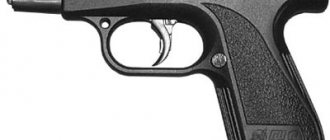
Frame
(Fig. 17) serves to connect all parts and mechanisms into a single pistol design. The frame with the base of the handle is one piece. The trigger guard serves to protect the trigger from accidental pressing and to support the second hand when shooting with two hands. In the front part of the frame there is a groove for placing a rod with a return spring and a tube of the bolt casing, a hole for the locking axis, a cutout for the bolt stop, a hole for the magazine release, and a window for placing the trigger. In the rear part of the frame there are holes for the safety axis, trigger and sear, a window for placing the trigger, sear with a spring and a pusher. In the front and rear parts of the frame there are longitudinal projections to guide movement along the grooves of the shutter casing.
Handle base
serves to secure the handle and store space. It has side windows (right and left) to reduce the weight of the pistol; lower window for store premises; on the rear wall there are lugs for attaching the handle stop latch; a hole for the handle stopper and a hole for attaching a pistol strap.
A - left side
B - right side
Rice. 17. Yarygin pistol frame:
1 — base of the handle; 2 — hole for magazine release; 3 — trigger guard; 4 — hole for the contactor axis; 5 — cutout for the bolt stop; 6 — hole for the fuse axis; 7 — hole for the trigger axis; 8 — hole for the sear axis; 9 - longitudinal projections to guide movement along the grooves of the shutter casing; 10 — groove for placing a rod with a return spring and a tube of the shutter casing; 11 — boss for attaching the handle stop latch; 12 — side windows (right and left) to reduce the weight of the pistol; 13 — hole for the handle stopper; 14 - hole for attaching a pistol strap.
Magazine release
(Fig. 18) serves to hold the magazine in the frame handle.
The push-button magazine release latch is located behind the pistol trigger guard and can be installed on either the right or left side of the handle (frame). After pressing the latch, the magazine falls out of the pistol handle under its own weight, which facilitates quick magazine changes. The pistol handle consists of a magazine latch, a magazine latch stopper, a magazine latch lock, and a magazine latch spring.
Rice. 18. Magazine release:
1 — magazine latch stopper, 2 — magazine latch; 3 — magazine latch spring; 4—magazine latch lock.
Fuse
(Fig. 19) serves to ensure safety when handling weapons.
Rice. 19. Double-sided fuse, located on the frame
A - view from the left side under the right hand;
B - view from the right side under the left hand
Fuse
(Fig. 20) has: a flag for moving the fuse from the “fire” position to the “safety” position and back; fuse box lock; a latch for holding the fuse in its assigned position; an axis on which a recess is made for the free movement of the sear when the trigger is pressed when the safety is switched to the “fire” position; a rib for locking the bolt with the frame when the safety is set to the “safety” position; protrusion for locking the sear in the “safety” position.
Rice. 20. Fuse:
1 — fuse box; 2 — fuse box lock; 3 — clamp for holding the fuse; 4 - axis; 5 - recess; 6 - rib; 7 - protrusion.
Trunk
(Fig. 21) serves to direct the flight of the bullet.
Rice. 21. Barrel:
1 - trunk; 2 - large protrusion for locking the barrel behind the window for ejecting cartridges in the bolt; 3 - coupling; 4 — chamber; 5 — ejector window; 6 - two bevel guides for cartridges dispensed from the magazine
It is placed in the shutter casing and connected to the frame using a contactor. Inside the barrel has a channel with six rifling, winding from left to right, the rifling serves to impart a rotational movement to the bullet. The spaces between the cuts are called margins. The distance between two opposite fields (in diameter) determines the caliber of the barrel. From the breech, the barrel bore is smooth and of a larger diameter; it serves to accommodate the cartridge and is called the chamber; it ends in two guide bevels for cartridges fired from the magazine, and a window for the ejector.
The stainless steel barrel has one large protrusion in the breech for locking the barrel behind the window for ejecting cartridges in the bolt (ejection is carried out by skewing it in a vertical plane).
Reducing the breech of the barrel for splitting with the bolt is carried out using a cam groove on the coupling under the barrel, interacting with the axis of the lock.
Stock
(Fig. 22) The return spring serves to guide the muzzle of the barrel when the bolt moves. It has a shaped head with a cutout for the locking axis, a support belt that rests against the barrel coupling. A return spring is placed on the rod.
Rice. 22.Stem:
1 — figured head with a cutout for the axis of the contactor; 2 — support belt; 3 - rod
Return spring
(Fig. 23), a twisted cylindrical one, is located under the barrel on the rod; it serves to return the bolt to the front position.
Rice. 23. Return spring
Pistol trigger mechanism
(Fig. 24) double action, with an open trigger, allows you to fire only single shots, both self-cocking and with pre-cocking of the hammer. The trigger mechanism consists of a hammer; whispered with a spring; trigger; descent rods; mainspring; pusher. The trigger and the trigger rod have a trigger spring and are connected to each other by the rod axis. The trigger and trigger rod are inserted into the frame and fixed by the trigger axis. The trigger and sear with a spring are connected to the frame using pins.
Rice. 24. Parts of the trigger mechanism:
1 — descent rod; 2 - trigger; 3 — trigger; 4 - traction axis; 5 — release spring; 6 - sear; 7 - sear spring; 8 — trigger axis; 9 — sear pin; 10—trigger pin; 11 — mainspring; 12 - pusher.
Trigger
(Fig. 25) is used to strike the firing pin, has a head with a notch for cocking the hammer by hand; on the front plane there is a cutout for the fuse protrusion, which ensures free movement of the trigger when it is released from the combat cock; at the base of the trigger there are two ledges: the lower one is a combat platoon; upper - safety cocking; between the combat and safety ledge there is a recess for the safety; on the right is a self-cocking tooth for cocking the trigger using the self-cocking tooth of the trigger rod; in the lower part of the trigger there is a platform for directing the travel of the trigger when firing by self-cocking; hole for connecting to the frame with a trigger pin. Inside the trigger has a groove for placing the pusher and a pin for the small eye of the pusher. The trigger is placed in the upper rear part of the frame.
The trigger is covered on the sides by bolt protrusions, which allows the cocked hammer to avoid getting caught on clothing items when removing the weapon from the holster.
A - left side
B - right side
Rice. 25. Trigger:
1 — head with a notch; 2 - cutout; 3 - combat platoon; 4 — safety platoon; 5 - undercut; 6 — self-cocking tooth; 7 - hole; 8 - platform; 9 - groove; 10 - pin.
Sear with spring
(Fig. 26) serves to hold the trigger on the combat and safety cock. It has: a spout for engaging the trigger ledges; the tooth on which the protrusion of the trigger rod acts. There is a spring on the front of the sear. The connection between the sear spring and the sear is made detachable - the end of the spring fits into a special recess. The spring presses the nose of the sear to the trigger. At the back of the sear there is a groove for the pusher. The sear has a hole for a pin, with which it is attached to the frame.
Rice. 26. Whispered:
1 - hole; 2 - pin; 3 - tooth; 4 - whisper spout; 5 - sear spring; 6 - recess; 7 - groove.
Trigger
(Fig. 27) is used to release the hammer from combat cocking, cocking the hammer when firing by self-cocking. The trigger is connected to the pistol frame by an axis. It has: a tail; hole for connecting to the frame; hole for connecting to the release rod; groove for the release spring.
Rice. 27. Trigger:
1 — hole for connecting to the descent rod; 2 — hole for connecting to the frame; 3 - tail; 4 — groove for the release spring.
Trigger pull
(Fig. 28) is used to release the hammer from cocking and cocking the hammer when pressing the tail of the trigger. In the front part it has a hole for connecting to the trigger; cutout for release spring; groove for connection with the trigger; the disconnecting protrusion of the trigger rod prevents the trigger from being released when the bolt is not completely closed; a protrusion that acts on the sear tooth when firing by self-cocking; a cutout on the protrusion that acts on the sear tooth when the trigger is released from cocking; self-cocking tooth of the trigger rod, which cocks the hammer when the tail of the trigger is pressed.
Rice. 28. Trigger pull:
1 — hole for connection with the trigger; 2 — cutout for the release spring; 3 — groove for connection with the trigger; 4 - disconnecting protrusion; 5 - protrusion; 6 — cutout on the ledge; 7 — self-cocking tooth of the descent rod.
Pusher
(Fig. 29) activates the trigger. The top of the pusher has a large and small eye. The small eye goes behind the trigger pin, the large eye goes into the trigger groove; in the middle part of the pusher there is a protrusion for the mainspring; The lower part of the pusher has a hole for a pin; it is attached to the socket of the handle stop latch.
Rice. 29. Pusher:
1 - small eye; 2 - large eye; 3 - protrusion; 4 - hole.
Action spring
(Fig. 30) operates the pusher. The upper end of the mainspring rests against the protrusion of the pusher, the lower end of the mainspring is inserted into the socket of the handle stop latch.
Rice. 30. Mainspring
Shop
(Fig. 31) is used to store and supply cartridges to the chambering line. The magazine consists of a body, a feeder, a feeder spring and a magazine cover.
Rice. 31. Store:
1 - holes; 2 — magazine cover; 3 — feeder; 4 — feeder spring; 5 — store body; 6 - cutout for latch latch.
Store body
(Fig. 32) connects all parts of the store. The upper edges of the side walls of the case are bent inward to hold the cartridges and feeder, as well as to guide the cartridges as they are fed into the chamber by the bolt. On the right side of the side wall of the magazine there are holes for visually determining the number of cartridges in the magazine. At the bottom there are curved ribs for the magazine cover. In the front of the magazine body there is a cutout for the magazine release latch.
Rice. 32. Magazine body:
1 - holes; 2 - curved rib; 3 - cutout for the latch latch.
Feeder
(Fig. 33) is used to supply cartridges. It has two bent ends that direct its movement in the magazine body. There is a bend inside the feeder to secure the feeder spring.
Rice. 33. Feeder:
1 — bent ends; 2 - bend.
Feeder spring
(Fig. 34) is used to feed upward the feeder with cartridges when firing. The lower end of the spring is bent to lock the magazine cover.
Rice. 34. Feeder spring
Magazine cover
(Fig. 35) has grooves with which it fits onto the curved ribs of the magazine body, and a hole for the bent (lower) end of the feeder spring.
Rice. 35. Magazine cover:
1 - grooves; 2 - hole.
Rice. 36. Contactor:
1 — flag protrusion; 2 — blade; 3 - platform with a notch; 4 - rod.
Contactor
(Fig. 36) a rod connects the bolt to the barrel in the pistol frame.
It consists of a protrusion (or tooth) of the locking flag, a blade, a notched platform, and a rod.
The protrusion (tooth) of the locking flag serves to hold the bolt in the rear position until all cartridges from the magazine are used up.
The notched platform is used to release the shutter by pressing the hand.
Reflector
(Fig. 37) is used to eject cartridges (cartridges) through a window in the bolt. The reflector has a hole in the front part for connection with the fuse lock and in the rear part there is a cutout that fits into the groove of the frame.
Rice. 37. Reflector:
1 - hole; 2 - cutout.
Lever
(Fig. 38) covers the side windows and the rear wall of the base of the handle and serves to make it easier to hold the pistol in your hand. It has a hole for the handle stopper, which secures the handle to the base of the frame.
Rice. 38. Handle:
1 — handle stopper; 2 — handle stopper hole.
Handle Stop Latch
(Fig. 39) serves to attach the handle. The bottom of the handle stop latch has a cutout for the handle stop; a socket for resting the lower end of the mainspring and a hole into which the pusher enters when the hammer is cocked; The top of the handle stop latch has holes on the sides for the handle latch stop. The handle latch stopper serves to secure the stopper latch to the base of the frame.
Rice. 39. Handle stop latch:
1 — handle latch stopper; 2 - socket; 3 — hole for the pusher; 4 - cutout; 5 — holes for the handle stopper.
Requirements for impact mechanisms of pistols and revolvers
The impact mechanism must satisfy the following basic requirements: reliably ignite the primer; prevent the breakthrough of powder gases through the primer; ensure the survivability of the striker; prevent firing a shot when the bolt is not completely closed. To successfully break the primer, the firing pin must have: sufficient kinetic energy from the mainspring; a certain speed of movement; the end of the striker must have a rational sharpening. The kinetic energy of the impactor is determined by the formula
mv2
E = -,
2
where m is the mass of the striker and the parts attached to it; V
- speed. The failure-free breaking of the capsule depends on the energy of the striker sufficient to ignite the capsule, therefore, when the striker speed decreases to a certain limit, misfires will appear. A reduction in the speed of the striker can be achieved by increasing its mass, contamination and thickening of the lubricant. The diameter of the striker and its shape also affect trouble-free ignition and survivability. The firing pin is the most fragile part, and its breakage leads to a delay in shooting. Therefore, when developing the design of the striker, it is necessary to: provide conditions for the operation of the striker so that there are no impacts on any parts of the bolt; exclude the possibility of the striker bending; in deciding whether the striker is sufficiently strong, proceed from a comparison of the designed striker with systems that have proven themselves in terms of strength; prescribe the correct heat treatment of the striker; make the firing pin easily replaceable; avoid sharp transitions in size in the sections of the striker and striker.
It is recommended to make the end of the firing pin rounded, since sharp firing pins lead to an increase in the duration of ignition of the primer, not to mention their lower strength; it is also necessary to have sufficient protrusion of the striker beyond the surface of the bolt. In systems with impact mechanisms powered by a mainspring, the energy of the striker is selected based on breaking the primer and the output of the striker is made large. The hole in the front wall of the bolt for the firing pin to exit must have a slightly larger diameter than the firing pin, both to avoid jamming of the firing pin due to contamination or thick grease, and to avoid damage to the firing pin when the firing pin sag due to the presence of gaps between the firing pin and its guides in the bolt.
A large gap for the firing pin in the bolt is dangerous, since the primer can be pressed into this gap, which leads to the breakthrough of powder gases, and sometimes to the primer being torn out of its socket. In domestic models of small arms this gap does not exceed 0.3 mm. Steels used for the manufacture of strikers must have sufficient toughness and wear resistance; Steels containing alloying impurities such as chromium, manganese and silicon satisfy this requirement quite fully. In conclusion, we can say that without changing the energy of the striker, it is always possible to select the most favorable shape and size of the striker, which produces the smallest number of misfires and ensures sufficient survivability.
Gate
Gate
We have already established that the barrel of a modern gun is a pipe.
The hole in the muzzle always remains open. The hole in the breech should only be open when loading; When firing, it must be tightly closed. This closing is done by a shutter. The barrels of guns loaded from the breech are equipped with bolts. During a shot, they take on the pressure of the powder gases. Therefore, the bolt must tightly close the barrel bore to prevent gases from escaping out. In addition, the bolt must reliably lock the barrel, that is, at the moment of firing, the bolt should not open spontaneously.
Reliably locking the bore when fired, the bolt should simply and easily open after a shot to reload the gun and close easily and tightly after loading. In this case, opening and closing the shutter should be done either with a simple hand movement without expending much effort, or automatically.
In large-caliber guns, the energy of special engines is used to open and close the bolts, since the bolts are very heavy.
The bolt is designed not only to close the barrel. It is equipped with mechanisms for firing a shot and for ejecting the cartridge case after the shot.
The types of shutters are very diverse. The most widely used valves are wedge and piston valves (Fig. 24).
Rice. 24. Types of valves: a - wedge valve with a horizontal wedge seat; b - wedge gate with a vertical wedge seat; c - piston valve
.
The wedge gate has the shape of a tetrahedral prism. The front face of such a prism is perpendicular to the axis of the barrel bore, and the rear supporting edge is inclined relative to the front. This is done in order to make it easier to open and close the bolt and ensure the tightest closure of the barrel. A wedge socket is a through slot in the breech of a gun. The shape of the socket in the breech corresponds to the shape of the wedge. When fired, the wedge rests on the edges of the grooves of the wedge socket. Depending on its direction, the wedge socket is called horizontal or vertical. In the first case, the wedge moves to the side, and in the second case it moves from top to bottom.
The horizontal movement of the wedge is advantageous, since in this case the force for opening and closing is distributed evenly, but it also requires space for the wedge to exit to the side. With a vertically moving wedge, the force on the handle is very uneven and, with a large weight of the wedge, it can be unbearable for a person, therefore, such shutters are equipped with special mechanisms in the form of springs, which are cocked when the shutter is opened and reduce the energy of the fall of the wedge, and when closing, make it easier to lift it.
When closing, the wedge slides into the socket and slides in it along guides parallel to the rear edge; the front edge, moving parallel to itself, approaches the rear edge of the barrel and delivers the cartridge to its place.
When opening, the inclined edges of the protrusions make it easy to extend the wedge and open the channel even when the bottom of the sleeve is strongly pressed against the front edge of the wedge.
When fired, the pressure of the powder gases on the front edge of the wedge is transferred through the rear edge to the wedge part of the breech. The tensile force can be decomposed into two components: one, directed perpendicular to the rear edge, tends to tear off the wedge part of the breech, the other, directed along the inclined edge, down or to the side, tends to throw the wedge out of its socket (see Fig. 24 6
). The greater the angle of inclination of the rear edge, the greater the force tending to throw the wedge out of its socket. In modern tools, this angle is close to zero, therefore, the force acting along the inclined edge is close to zero.
The breech itself prevents the wedged part of the breech from coming off, and the friction force counteracts the ejection of the wedge from the socket.
Thanks to the presence of a wedge socket with grooves, the length of the breech part of the gun is reduced, which is undoubtedly beneficial. However, this design is less durable, since the cheeks of the socket, not connected at the back, can come apart. This type of wedge socket is used mainly in small-caliber guns. The use of a wedge socket with shaped grooves eliminates the possibility of cheek divergence.
In modern artillery, wedge bolts are usually used in guns with separate case and cartridge loading. In these cases, obturation and protection against gas breakthrough is provided by the sleeve itself, which, expanding under the pressure of powder gases, is tightly pressed with the outer surface to the walls of the chamber, as a result of which gas breakthrough to the outside is eliminated. Therefore, the use of a wedge bolt for separate case and cartridge loading does not require the use of any special sealing devices.
In older systems, the wedge breech was used in cap-loading guns. Obturation in these tools was ensured by a special device - an obturator. But the obturating devices used did not give good results. Therefore, the wedge bolt is not used for case loading in modern artillery guns.
Compared to other types of bolts, the wedge bolt has a simpler design and reliably locks the barrel bore. Closing and opening the wedge requires one straight-line movement, which ensures the simplicity and speed of operation of such a valve, especially since elevation angles do not affect the amount of force required for opening and closing, especially in valves with a horizontal wedge. This circumstance facilitates the automation of wedge valves. In modern artillery, semi-automatic bolts are in most cases wedge-type.
Vertical wedge gates are usually used in small-caliber guns, where the weight of the wedge is small and the change in forces on the handles when opening and closing is negligible, as well as in guns where opening and closing is automatic. The use of vertical wedge gates is advantageous in cases in which the sideways extension of the wedge limits the angle of horizontal fire due to the emphasis on the carriage frame or other parts of the gun.
In addition to manually operated wedge valves, there are also semi-automatic and automatic ones. Full or partial automation is carried out by using the force of powder gases during recoil.
Semi-automatic bolts use this force to open, eject the spent cartridge, and close. Loading and firing a shot is done manually. Most modern small and medium caliber artillery pieces have a semi-automatic breech. These weapons include the 45-mm anti-tank gun mod. 1937 and arr. 1942, 76-mm gun mod. 1939 and model 1942, etc. There are bolts in which only closing is automated (76-mm mountain gun model 1938).
During firing, without any effort from the gun crew as a result of the action of powder gases, the automatic shutter opens, loads the gun, closes, fires a shot and ejects the spent cartridge case. Small caliber anti-aircraft guns, as a rule, have automatic shutters.
In addition to wedge bolts, some artillery guns also have piston bolts.
Piston valves are used in medium and large caliber guns. The main part of the locking mechanism of a piston valve is a cylinder with a screw thread on the outer surface, called a piston. When the bolt is closed, the piston is screwed into the rifled bolt seat of the barrel, ensuring reliable locking of the barrel when fired. The high pressure of the powder gases on the piston necessitates a larger number of turns. The design of such a piston, in the form of an ordinary screw, would require a lot of time to open and close the shutter. To speed up the operation of the bolt, the threads on the piston and in the bolt seat are not made along the entire circumference, but alternate with smooth sections. The most commonly used pistons have two grooved and two smooth sections. In such a piston, each section corresponds to a sector with an angle of 90 degrees. There are pistons with three and four pairs of threaded and smooth sections.
When closing, the piston is installed with threaded sectors against the smooth sectors of the bolt seat and in this position is pushed into the seat over its entire length. After the piston is pushed in, it rotates at a certain angle (90, 60, 45 degrees), while the piston coils engage with the bolt seat coils. Thus, instead of a large number of revolutions of the piston around the axis, closing is done by turning it through a small angle.
Cutting off part of the turns speeds up the operation of the bolt, but at the same time reduces the strength of the piston in the barrel. To increase the strength of engagement, the number of turns on the piston is increased, which causes an increase in the length of the piston, and therefore an increase in its weight. Both of these factors reduce the gun's rate of fire.
To reduce the length and weight of the piston and increase the strength of its connection with the breech, so-called stepped pistons are sometimes used. Such pistons have sectors of different heights, that is, the cutting is done with different diameters, according to which the bolt seat is cut.
Some valves use conical stepped pistons. The diameter of such a piston increases towards the breech. This makes it possible to reduce the length of the piston, since due to an increase in the diameter of the coils, the strength of the piston increases. However, conical pistons are rarely used due to the complexity of their manufacture. Frictional forces arising at the point of contact between the surfaces of the piston turns and the bolt seat prevent the piston from turning under the action of powder gases. In addition, the shutter in the closed position is locked with special devices, which also eliminates the possibility of opening the shutter when firing.
Obturation in piston bolts of guns with separate cartridge and cartridge loading, as in wedge bolts, is ensured by the sleeve. The situation is somewhat different with case loading. When the bolt is closed, a small gap is formed at the point of contact with the body of the gun, through which highly heated gases can break through. Gases passing through the gap at high speed can melt the metal and, thus, render the valve unusable. In addition, these gases, escaping back, can cause severe damage to the gun crew. And finally, the destructive effect of gases can damage other parts of the shutter that are not designed for high forces. Gas breakthrough cannot be eliminated by careful processing and precise adjustment of the contacting surfaces, because gases constantly strive to tear the bolt out of the gun and penetrate into any free space. Since gas breakthrough is completely unacceptable, the valve itself must have a special device that prevents the flow of gases. This device is called a seal.
The seal must be made of plastic material so that under pressure it can take the shape of surrounding surfaces. The shutter is placed in the breech so as to cover the gap between the bolt and the body of the gun when fired.
In modern shutters, only automatically operating seals are used, that is, those in which tight locking is carried out exclusively under the influence of the pressure of the powder gases. Automatic seals can be divided into two groups: the first - seals whose action is based on compression, the second - seals whose action is based on stretching. The first group includes a mushroom-shaped seal, the second group includes metal sleeves and trays.
The mushroom-shaped seal (Fig. 25) consists mainly of an annular cushion and a mushroom-shaped rod.
Rice. 25. Shutter with mushroom seal
.
The ring pillow is made of canvas, stuffed with asbestos, soaked in lamb fat and pressed under high pressure. It is placed on the front end of the piston and is held in place by a mushroom-shaped rod that has a through ignition channel. The mushroom-shaped rod has the ability to move somewhat along the axis.
At the moment of firing, under the influence of powder gases, the mushroom-shaped rod moves backward and flattens the cushion, which is pressed against the walls of the chamber, eliminating the possibility of gas breakthrough. To ensure that the cushion material is not pressed into the gaps between the bolt and the barrel, the seal has steel split rings, which, under the pressure of the cushion, when fired, are unclenched and pressed against the corresponding surfaces. Due to the elasticity of the cushion and rings, after the shot they return to their original dimensions and do not make it difficult to open the bolt.
To close the bolt, the piston is installed with threaded sectors against the smooth sectors of the bolt seat and is pushed in to its entire length, after which the piston is rotated at a certain angle so that its turns engage with the turns of the bolt seat. Consequently, the translational and rotational movements of the piston when opening and closing are performed by a simple action on the handle. For ease of opening and closing, the piston is mounted in a frame pivotally connected to the barrel breech using an axle. At the end of the axis there is a handle. To close the bolt, you need to turn the handle all the way to the breech. This will cause the shutter to close completely.
Based on the number of simple piston movements performed when opening and closing the valve, two- and three-stroke piston valves differ.
In push-pull piston valves, when closing, the piston moves along with the frame in an arc until it is completely inserted into the bolt seat, and then rotates around the axis, screwing into the seat. When opening the shutter, the movement is performed in the reverse order.
In three-stroke piston bolts, when closing the bolt together with the frame, the piston is brought to the breech section, moving along a circular arc, then moves out of the frame and slides into the piston seat, moving along the axis of the barrel bore, and rotates until the threaded sections are completely engaged, in other words, the piston is screwed into bolt socket. When opening the shutter, the movement occurs in the reverse order.
According to the location of the frame axis, piston valves, like wedge valves, can be horizontal or vertical. In the first case, the frame axis is located vertically, and the rotation of the frame together with the piston occurs in a horizontal plane. In the second case, the frame axis is located horizontally, and the piston rotates together with the frame in a vertical plane.
We have already said that the bolt is designed not only to lock the barrel, so the design of a modern bolt, in addition to the locking device, includes several other mechanisms.
The main mechanism of any shutter is the locking mechanism.
In wedge valves, the locking mechanism consists mainly of a wedge that moves using cranks and a handle mounted on one axis (Fig. 26 a
). The crank rollers fit into grooves on the wedge. When the handle moves forward, the crank rollers press on the edges of the grooves, forcing the wedge to lower, as a result of which the barrel bore opens. To close the bolt, the handle must be turned back.
Rice. 26. a - locking mechanics of the wedge gate; b - locking mechanism of the piston valve; c - impact mechanism of the wedge gate; d - firing device of the piston bolt.
In a push-pull piston valve, the locking mechanism consists of a piston (Fig. 26 b
), frame, comb and handle mounted on an axis. When you turn the handle back, the spike of the handle will pull the comb, which with its teeth is engaged with the toothed sector of the piston. The piston will rotate around its axis until its threaded sectors disengage from the threaded sections of the piston seat. At the moment of complete disengagement, the protrusion on the handle axis will rest against the edge of the arc groove on the frame. Further movement of the handle will be associated with the movement of the frame itself, which, together with the piston, will rotate around the axis of the frame and remove the piston from the socket. The shutter is closed by moving the handle in the opposite direction.
Vertical valves use a balancing mechanism to eliminate the influence of the weight of the wedge or piston when opening and closing the valve. When the shutter is opened, the lever mounted on the handle axis compresses the spring of the mechanism. The force of the compressed spring balances the weight of the shutter, so closing it is easy and effortless. In wedge valves, the force of the compressed spring exceeds the weight of the valve; in this case the shutter closes automatically.
To prevent spontaneous opening of the shutter, there is a special closing device that is included in the locking mechanism. In a wedge valve, such a device is an arc section of the groove and a recess for the crank roller. The wedge cannot move until the handle with the cranks rotates through a certain angle and the roller comes out onto a straight section of the groove.
In a piston valve, locking is done using the tooth of the handle. To open the bolt, you need to push the handle down, this will disengage the tooth from the frame and the handle can be turned.
In Fig. Figure 24 shows an open wedge gate and a horizontal wedge seat.
To fire a shot, there is a firing device in the bolt. In wedge gates, the most common firing devices are those consisting of a striker and a trigger mechanism.
The impact mechanism consists of a striker, cocking, mainspring and cover (Fig. 26c
). The mainspring is placed between the firing pin partition and the cover secured in the firing mechanism socket. To fire a shot, the firing pin must be pulled back and thereby compress the mainspring; then release it. Under the action of the expanding mainspring, the firing pin will sharply move forward and strike the cartridge case primer with its striker.
The firing device of the piston bolt is placed inside the frame pipe, around which the piston rotates (Fig. 26 a
). The main parts of the device are a firing pin with a firing pin, cocking and support sleeve or nut, a mainspring, a firing pin tube and a trigger with a roller.
How does the shooting device work? Pull the long trigger arm towards you. The trigger will begin to rotate around its axis and its hook will pull the firing pin back. At the same time, the short arm of the trigger with its roller will begin to press on the tail of the firing pin tube, sending it forward. The mainspring, enclosed between the firing pin support sleeve and the annular shoulder of the tube, is compressed. But then the firing pin platoon breaks away from the trigger hook and the firing pin with the clutch begins to move forward under the action of the compressed mainspring; Having encountered a piston ledge on its way, the clutch stops. The firing pin moves further by inertia, the firing pin extends beyond the front cut of the piston and breaks the cartridge case primer. If the piston is not fully engaged with the bolt socket coils, that is, the bolt is not completely closed, it is impossible to fire a shot. In this case, the hammer tube with its tail rests against the arc protrusion of the piston.
Pulling the trigger to fire a shot is done using a trigger cord or a trigger rod mechanism.
Occasionally there are such cases: you release the striker, but there is no shot. After some time, a shot is heard completely unexpectedly. What happened? There was, as the artillerymen say, a prolonged shot. Premature opening of the bolt during prolonged shots is very dangerous and can lead to injury to the gun crew or disable the gun. To avoid this, modern guns use inertia-type fuses in case of prolonged shots.
The main part of such a fuse is a massive body, which is placed either in the bolt or in the breech and can move in its socket along the axis of the barrel. When the bolt is closed, the fuse moves so that it connects any part of the bolt with the breech. Consequently, it is no longer possible to open the shutter with a normal movement. During recoil or rewind, due to inertia, the safety releases that part of the bolt that it connected to the breech during closing, and then the bolt can be opened with a simple movement. But if the shot does not occur, then you can open the shutter only after turning off the safety.
To eject the spent cartridge case after a shot, both types of bolts have special ejection devices, the action of which is based on the principle of a first-class lever. Typically, the ejector consists of one or two branches mounted on one common axis. The axis serves as a support during the action of the ejector.
In addition to the mechanisms described above, the breech of modern guns has folding trays, which serve to guide heavy projectiles during loading. To prevent the head of the projectile or the leading band from touching the protrusions and irregularities in the bolt socket during loading, there are guide strips. The guide bar must ensure free sliding of the projectile during loading; in order to remove the guide bar when closing the shutter, no additional movements are needed: the bar is raised and lowered using a lever mounted on an axis connected to the shutter handle. When you turn the lever, the bar rises and moves slightly forward. When the lever is turned back, it lowers and does not interfere with closing the shutter.
A retainer is sometimes placed in the upper part of the bolt socket, the purpose of which is to prevent the cartridge case or cartridge from falling out when loading at large elevation angles. When the bolt is opened, under the influence of its own weight, the long end of the holder lowers and remains in an inclined position, freely allowing the projectile and cartridge case to pass through during loading, but not allowing them to fall out. When the bolt is closed, the piston raises the retainer.
Ejection mechanism of pistols and revolvers
Purpose and working conditions.
The ejection mechanism serves to extract (extract) the cartridge case (cartridge) and remove it outside the weapon. The cartridge case is removed by the ejector, and removed by the reflector (ejector). For revolvers, cartridge case extraction follows different schemes and will be discussed further. In non-automatic weapons, the extraction of the spent cartridge case from the chamber is carried out some time after the shot, when all the powder gases have come out of the barrel and the outer surface of the cartridge case is not pressed against the surface of the chamber by the pressure of the powder gases.
Therefore, it does not require much effort to remove the cartridge case. For automatic pistols, we will consider only the most commonly encountered systems. In blowback and blowback systems, the spent cartridge case is removed at high pressure in the barrel bore. The ejector is practically not involved in removing the cartridge case. The cartridge case is pushed by the pressure of the powder gases onto the inner surface of the bottom of the cartridge case. Removal of the cartridge case occurs when there is significant friction between the walls of the cartridge case and the walls of the chamber.
The ejector only holds the cartridge case until it meets the reflector. In systems with a short stroke and with removal of powder gases, extraction occurs in the presence of a certain pressure of the powder gases. But, as experiments conducted with shooting with a remote ejector have shown, this pressure is enough to successfully remove the cartridge case, especially with a lubricated cartridge case. In systems with a long barrel stroke, the cartridge case is removed from the chamber when the powder gases have completely flowed out of the barrel, which creates favorable conditions for extraction.
Automatic weapons. Semi-free shutter.
Maxim Popenker.
In the previous article, we briefly examined the simplest scheme for automatic small arms - blowback systems, characterized in that the bolt does not have a rigid grip with the barrel or receiver at the moment of firing. In this article we will look at semi-blowback systems. What these designs have in common with blowback systems is that the only source of energy for reloading the weapon in them is the pressure of the powder gases at the bottom of the cartridge case, transmitted to the bolt, and that at the initial moment of the shot the bolt does not have a rigid grip with the barrel or receiver. Upon closer examination, blowback weapons can be divided into two subclasses. In the first, the bolt moves continuously throughout the entire automation cycle, but in the first part of the cycle, while the pressure in the chamber is still high, its movement slows down in one way or another. In the second, after a short “jerk” back, the bolt is forced to stop at such a distance from the breech of the barrel that the cartridge case partially released from the chamber is not torn apart by internal pressure; after a short pause, the bolt is released and, under the influence of the inertia of the bolt frame and the residual pressure in the barrel, completes the reloading cycle. It should be noted that weapons made according to the first option are much more numerous than systems with a full shutter stop. Gate-braking circuits have many implementation options, most of which were developed before or during World War II. None of the schemes was particularly widespread, despite the commercial success of a number of models of semi-blowback weapons.
The first examples of weapons using a semi-blowback appeared in Europe at the end of the 19th century. One of the most famous systems of that time was the development of the legendary Austrian Ferdinand von Mannlicher, patented in 1893. In his patent, Mannlicher described a military rifle with a longitudinally sliding rotary bolt. Its peculiarity was that both the protrusions on the bolt and the grooves in the receiver had a screw shape, so that under the pressure of the powder gases on the bottom of the cartridge case, the semi-free bolt self-unlocked, turning until it was completely disengaged from the receiver. The system turned out to be unsuccessful, since the unlocking of the bolt ended at a sufficiently high gas pressure, which led to frequent ruptures of the cartridges and high recoil speeds of the bolt. Nevertheless, other designers later turned to a similar scheme several times. In particular, the system of the American Blish, implemented in experimental automatic rifles and serial Thompson submachine guns, can be considered a development of Mannlicher’s scheme. A certain analogue of the Mannlicher system was the system used by the Italian Revelli in the Villar-Perosa submachine guns. At the same time, experience has shown that for pistol cartridges such a design was, in principle, redundant, and during the Second World War, Thompson M1 submachine guns were already produced with a conventional blowback action.
patent for a Mannlicher semi-blowback semi-automatic rifle
The first truly successful example of a blowback weapon was, oddly enough, a machine gun designed by the German Andreas Schwarzlose, which was adopted by the army of the Austro-Hungarian Empire in 1907. This machine gun had an original scheme for slowing down the bolt's recoil due to an articulated pair of levers, which in the forward position were close to the dead center position. To ensure reliable extraction of cartridges in conditions of the beginning of recoil at high pressures in the barrel, the machine gun had a built-in oiler that supplied a small drop of oil to the chamber before each shot. In general, the extraction of cartridges in semi-blowback systems has become one of the stumbling blocks to the development of this scheme. Designers had to resort to lubricating the cartridges (as, for example, the American Pedersen did in his self-loading rifle), or introduce longitudinal grooves in the chamber, leading along the body of the cartridge case from its muzzle. The powder gases that entered these grooves immediately after the bullet exited the cartridge case partially compensated for the inflation of the cartridge case by the internal pressure of the gases. Both schemes led to increased contamination of weapon mechanisms, which became especially unpleasant in difficult operating conditions “in the field”, typical for army weapons.
patent for a Schwarzlose machine gun
In the mid-thirties, samples of weapons appeared with full braking of the bolt after a short rollback. This was a family of MKMO and MKRO submachine guns (differing mainly in size), created at the Swiss SIG plant by designers Kiraly and End. In these submachine guns, the bolt group consisted of two parts - a lightweight bolt and a massive bolt frame. After the shot, the bolt group assembly rolled back about 6 millimeters, after which the bolt, with a protrusion in its rear upper part, rested against the rear edge of the window for ejecting spent cartridges in the receiver. The bolt frame continued to move backward by inertia, and after a few more millimeters of independent rollback, its bevels lowered the bolt, uncoupling it from the receiver, and then dragging it along with it. This typically Swiss design (that is, complex, expensive and executed at the highest level of quality) generally worked well, and even ended up in service with the Vatican guards. However, the excessive price led to the fact that in 1937, simplified versions of the MKMS and MKPS with a conventional blowback bolt were developed to replace these submachine guns, which worked no worse.
Around the same time (late thirties), one of the developers, Pal Kiraly, returned to his historical homeland, Hungary, where he continued work on blowback weapons. In 1939, the Hungarian Army adopted the 39M submachine gun of his design, based on a number of patents, the first of which was obtained by Kiraly back in 1910. These patents were based on a design consisting of a lightweight bolt and a massive bolt carrier, between which there was a swinging lever. The axis of the lever was located on the bolt, its upper arm rested against the bolt frame, and the lower arm rested against the transverse stop in the receiver. Immediately after the shot, the rollback of the bolt caused the lever to rotate due to the interaction of its lower shoulder with the stationary receiver. At the same time, the upper arm energetically accelerated the massive bolt frame, thereby, according to the rule of the lever, for a short time increasing the force opposing the opening of the bolt and thus inhibiting its rollback. After the initial period of recoil, the lower arm of the lever was rotated all the way and then the bolt and bolt frame continued to move at the same speed, by inertia. This system turned out to be relatively successful overall, and in the post-war period it was more or less successfully used in a number of designs, including the French AA 52 single machine gun and FA MAS assault rifle. It is interesting that in the late 1950s and early 1960s, a similar automation scheme was widely experimented in the USSR as part of work on promising lightweight automatic machines. Among others, the designer Korobov was noted in this field, but extensive and very severe tests at Soviet test sites established that such a system, for all its advantages, is inferior to gas-operated automation in the main thing - reliability, especially in difficult operating conditions.
patent for a system with shutter braking using a lever by designer Pal Kiraly
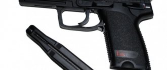
Among the not too large number of semi-blowback systems created by the mid-20th century, one stands out, developed in parallel by two German companies at the end of the Second World War. We are, of course, talking about the most commercially successful system, in which the shutter rollback is braked using a pair of rollers located between the shutter and the massive bolt frame. This system was created on the basis of the system with rigid locking of the barrel using rollers, successfully used in the MG-42 machine gun, and priority in its creation belonged to two independently operating companies - Grossfuss, which was engaged in simplifying the MG-42 machine gun within the framework of the MG.42(V) project. / MG.45, and Mauser, which developed the Gerat 06(H) / Stg.45(M) assault rifle. After the war, some German engineers immigrated to Spain, where at the CETME weapons center they perfected this design, creating by the end of the 1950s the CETME Mod.B automatic rifle, which used a semi-blowback. In 1959, for a number of political reasons, this rifle was adopted in Germany and put into mass production at Heckler und Koch. It was the engineers and marketers of this company who were able to develop the design of the rifle into a whole family of small arms, based on the general principles of automation and production technologies. In addition to the G3 automatic rifles of 7.62x51 NATO caliber, this family included machine guns of 7.62x51 and 5.56x45 NATO calibers, sniper rifles, a pistol and a submachine gun. It was the latter that turned out to be the most successful and long-lived model of a blowback weapon - the already legendary NK MP5 submachine gun has been produced for more than 50 years not only in Germany, but also in a number of countries, and is in service with special forces of the army and police in dozens of countries peace on all continents. In addition to the NK weapon and its copies and clones, similar automatics with a roller braked bolt were used in several other types of small arms, in particular, the American Calico submachine guns and SRM 1216 smoothbore self-loading shotguns.
patent for a semi-blowback roller brake system
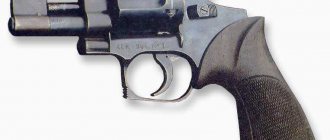
Much less success awaited another German system, also created at the end of the war. We are talking about a gas-braked bolt system used in the Rheinmetall VG.1-5 self-loading carbine. In this system, the semi-free bolt was rigidly connected to a cylindrical casing that covered the barrel almost to the muzzle. In the front part of the casing there was a cylindrical region of variable volume, formed at the rear end by a thickening of the barrel, and at the front - by a casing plug that tightly fit the barrel. Powder gases were diverted into this area from the bore through transverse holes. Their pressure from the inside on the casing plug, which tended to move back behind the bolt, slowed down this movement until the bullet exited the barrel. The system was, in principle, operational, but it suffered from rapid overheating and clogging with soot from powder gases. In the post-war period, this system, in a slightly modernized version, was used in the Austrian Steyr GB pistol, also without much success. A version of this system with a gas cylinder separate from the barrel, placed in a shack under the barrel and with a gas piston entering it from the front connected to the bolt, was used in several pistols, the most successful and famous of which was the German NK P7 pistol. However, this system did not catch on, despite its relative simplicity.
diagram of a system with gas braking of the bolt used in the Steyr GB pistol
In general, we must state that systems using a semi-blowback have never been particularly popular, and individual successful exceptions rather confirm this rule. In fact, the most successful and still produced weapon of this design, the NK MP5 submachine gun, could well be implemented using a blowback design without any noticeable damage to its characteristics. As for weapons chambered for more powerful intermediate and rifle-machine-gun cartridges, the comparative simplicity of semi-blowback systems is largely offset by the increased sensitivity of weapons to the material of the cartridge cases, increased contamination of weapon mechanisms with powder gases, and an increased likelihood of unpleasant delays in firing caused by transverse ruptures of liners.
Designs of the ejection mechanism of pistols and revolvers
The main part of the ejection mechanism is the ejector. The peculiarity of the ejector operation is that it experiences shock loads, having extremely limited dimensions. This results in the ejector being subject to relatively frequent breakdowns. Therefore, the following requirements are imposed on it: have high strength; securely hold the cartridge case until it is reflected outside the weapon.
Schemes of operation of movably fixed (above) and rigid ejectors:
1 - sleeve; 2 - ejector; 3 - shutter.
Strength is achieved by design and choice of metal - special alloy steel. Reliable retention of the cartridge case by the ejector is ensured by establishing a strictly defined distance between the ejector hook and the bottom of the bolt cup, as well as by imparting springiness to the ejector. The smallest distance between the ejector hook and the bottom of the bolt cup must be no less than the thickness of the rim of the sleeve.
The largest distance is determined experimentally: it depends on the design of the ejection mechanism. The required springiness of the ejector is achieved by correctly choosing the stiffness of its spring part or by using a special ejector spring. Reliable retention of the cartridge case is ensured by the fact that the ejector hook, when removing the cartridge case, presses it against the wall of the bolt cup. To ensure that the cartridge is captured, the ejector hook is drawn along a circular arc corresponding to the circumference of the cartridge case. The width of the ejector hook is 50-60% of the diameter of the bottom of the cartridge case for rifles, machine guns and submachine guns and 25-50% for pistols. To increase the survivability of the ejector, the outline of the ejector should not contain sharp angles or transitions in order to avoid increased local stresses, and strict symmetry should be ensured, eliminating the possibility of the sleeve engaging with only one edge of the ejector. The ejector socket should not allow it to become distorted.
A bevel is made on the front plane of the ejector hook, which ensures that the hook can easily jump over the edge of the cartridge case when the cartridge is chambered. The design and operating principle of the ejection mechanism depends on the type of shutter. Pistols use a sliding bolt type. During the forward movement of the bolt, the cartridge case captured by the ejector moves backward with the bolt until it encounters a reflector, which removes the case from the weapon. The following ejectors are available for this type of bolt. ejector with spring part. The spring part of the ejector allows it to easily jump over the edge of the cartridge case and hold it with its hook in the bolt cup; ejector with leaf spring.
Here the ejection mechanism consists of two parts: the ejector and the leaf spring. The spring here acts as a spring-loaded part, as in the first type of ejector; ejector with a helical coil spring. The location of the spring can be either parallel to the shutter axis or perpendicular. The main advantage of this type is greater survivability. Many designs of this type provide a self-tightening ejector.
Forces acting on the ejector
with a coil spring.
Self-tightening is carried out thanks to the presence of a shoulder l
1 between
forces
P
and
R. The sleeve extraction force P
and the ejector reaction
R
form a pair of forces with shoulder
l
1.
M = P l 1
This pair provides a rotating moment that turns the ejector and presses it against the sleeve. The spring strengthens the pressure of the ejector with its force R
. The reflector serves to remove (reflect) the cartridge case outside the weapon. The main requirement for the reflector is to ensure reliable removal of the cartridge case outside the weapon in a certain direction. The direction of removal of the sleeve is ensured by the appropriate relative position of the ejector and reflector. Typically, the ejector is located on the side of the window for reflected cartridges, and the reflector is on the opposite side. Reflectors are varied in design and can be a protrusion, a pin or a lever. All of them can be divided into two groups: hard and spring. Rigid reflectors are: rigidly fixed. These reflectors are simple in design, but require a deep slot in the shutter; fixed in the receiver on an axis; mounted in moving parts.
The effect of reflectors of this type is as follows: when the bolt moves backward, the reflection of the cartridge case occurs due to the impact of the rear end of the reflector on the ledge of the receiver. All rigid reflectors are simple in design, but during operation they give sharp shocks. Spring reflectors come in two types: fixed in the stationary part of the weapon.
Used in weapons that have a buffer; the reflector spring is connected to the moving parts of the weapon. Here the reflector is driven by its spring. When the cartridge is chambered, the reflector is recessed by the bottom of the cartridge case, which compresses the spring with its rear end. As soon as the cartridge case leaves the chamber, the reflector, moving under the action of its spring, removes it outside the weapon; for this, the spring must be stiff enough. Some striker-fired pistols use a firing pin as a spring deflector.
Weapon bolt
Details Category:
WEAPONS SHUTTER
, part of a firearm loaded from the treasury, used to close the barrel bore before firing.
Gun bolts are divided into sliding, folding, crane and swinging.
1. Sliding gates. Currently, the armies of almost all countries are armed with bolt-action rifles, which have the following advantages: 1) reliability of cartridge case extraction; 2) ease of separation and removal of the sliding bolt from the receiver; 3) ease of replacement of the shutter and 4) simplicity and ease of manufacture when processed on a machine. Sliding valves are divided into direct-acting valves and rotating valves. When closing the bolt of the first type, you just need to push it forward - and the rifle will be loaded and the firing pin cocked (Austrian and Swiss model 1895). A straight-action bolt is advantageous in that the shooter can fire several shots without removing the rifle from his shoulder, but at the same time, this bolt is easily susceptible to contamination and malfunction. Therefore, a sliding bolt with a rotation is more common, requiring two movements - rotation of the bolt and its linear movement (rifle model 1891, which is in service with the Red Army, Lebel model 1907/15, Lee-Enfield model 1903, Arisaka model 1905 g., Mauser, Mannlicher).
The front part of the receiver is screwed onto the rear section of the barrel and serves to house the bolt (Fig. 1) (which combines the locking and impact mechanisms), the trigger mechanism and the ejection device.
Protrusions on the inner surface of the bolt stem fit into screw cutouts, causing the action cylinder to rotate as the bolt moves forward. The combat larva (Fig. 2) has 2 protrusions that fit into the transverse grooves of the box.
The tightness of closing the barrel bore depends on the correct pressing of the combat cylinder on the bottom of the cartridge. When the bolt is opened, the ejector (Fig. 3), with a hook slightly protruding beyond the front plane of the combat cylinder, grabs the edge of the cartridge case located in the chamber and pulls the cartridge case until it hits the protrusion of the cutoff-reflector and is ejected, so-called. O. from the receiver.
There is a firing pin running inside the bolt stem (Fig. 4), which breaks the cartridge primer when fired; On the long part of the firing pin there is a mainspring, which serves to impart rapid movement to the firing pin in order to receive a strong blow from the firing pin on the primer.
A trigger is screwed onto the rear end of the firing pin (Fig. 5), which pulls the firing pin back and holds it in the combat or safety cocking position.
The trigger ends at the rear with a button, with the help of which, without opening the bolt, you can pull the hammer back to put it into combat or safety cocking (in the latter position, you can neither pull the trigger nor open the bolt). For the bolts of automatic rifles and machine guns, see Automatic Weapons.
2. Flap valves are divided into: a) moving in a vertical transverse plane, i.e. with a bolt located parallel to the channel axis (folding to the left - Krnka system, to the right - Schneider system); b) moving in a vertical longitudinal plane, i.e. with a bolt located horizontally and perpendicular to the axis of the channel (folding upward - Berdan No. 1, Wenzl, Remington systems).
3. Crane valves are a cylinder with a special cut-out part in the form of a groove for inserting cartridges, its base adjacent to the breech end of the barrel and rotating around an axis parallel to the axis of the channel.
4. Swinging gates have limited movement in the vertical longitudinal plane, rotating about a horizontal axis located perpendicular to the channel axis.
Artillery and gun valves are divided into two types: wedge valves and piston valves.
The idea of a wedge bolt is that a wedge is pressed or pushed into the transverse hole in the gun from the side or bottom (Fig. 6).
When the wedge is pushed in, its rear surface (cd) slides along the wall of the socket, and the front plane (ef) gradually approaches the front wall of the wedge hole (gh) and finally presses against it. When opening the wedge, its front plane (ef) moves away from the plane (gh), while the rear inclined plane of the wedge (cd) is always adjacent to the rear inclined plane (ab) of the wedge hole. To press the front plane of the wedge more tightly against the walls of the socket, in order to avoid leakage of gases, elastic gaskets (metal, leather, rubber) are used. Such devices are called abturators. Wedge gates were introduced in the field guns of previous models (Fig. 7).
When locking the shutter using handle B, move wedge A until the cut of the tile (cd) of the wedge touches the cut of the ring (ab); When moving further, to finally lock the bolt, you must turn the same handle to tighten the clamping screw (u). The threaded part of the screw consists of several steep turns, half protruding above the surface of the wedge and included in the corresponding thread of the half-wedge cut into the body of the gun. The clamping screw, in addition to facilitating the final locking of the bolt, also serves as a connection between the wedge and the body of the gun, which eliminates the possibility of the bolt being thrown out of the socket by the action of powder gases. To speed up the locking of the bolt, the turns of the screw, except for the outermost one adjacent to the board (w), are cut off on one side so much that they do not protrude beyond the upper plane of the wedge surface. With this device, when the screw is turned with the cut part of the turns upward, you can manually push the shutter until the end of the remaining uncut end of the turn stops in the half-thread; further retraction of the bolt (the so-called clamp) is performed by rotating handle B 1/2 turn, due to which the entire screw is screwed into the semi-wedge and a strong connection of the wedge with the body of the gun is achieved (as in a piston bolt). In the wedge bolt for 48-line (105 mm) howitzers of the 1909 model, the ABC crank handle is used to open and close the bolt (Fig. 8).
When the handle is turned in a horizontal plane to the right back, the inner knee C of the handle extends the wedge, due to the fact that the lower fist O at the end of the knee moves in the oblique groove F on the surface of the wedge, and the upper fist O moves in the circular groove F1 of the gun casing. The sliding of the wedge is limited by its outer front board, which is larger than the wedge hole.
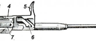
The idea of a piston valve is that a special piston B is screwed into the breech of channel A (Fig. 9), equipped with a screw thread, like a screw. The threads of the piston and its sockets are cut in the longitudinal direction on parts (a).
By placing the sector (b) of the cut turns of the piston against the cut turns (a) of the socket, you can freely push the piston in and out. When the retracted piston is rotated through the angle of the sector of turns, the piston cutting bits engage with the socket cutting; in this case, the piston is connected to the tool and cannot. pushed out or expelled by gas pressure. To open the shutter, turn it back to the same angle, and the thread of the piston is disengaged from the thread of the socket. The piston bolt (Figs. 10 and 11) of the 76-mm field gun of the 1902 model consists of a locking, impact and ejection mechanisms and a fuse.
The bolt body A forms a piston with 2 sectors of turns that engage when the piston is turned with the same turns of the sectors of the socket of the locking part B of the barrel. To remove the piston and hold it in the required position, a frame C is used, which runs between the eyes D of the body of the gun and is connected to it by an axis that is integral with the handle E, on which there is a handle F.
When the handle is turned to the right, its spike, acting on a special comb, moves the latter in the groove of the frame. The comb with its teeth turns the piston by its teeth until the threaded turns of the piston come out of engagement with the threaded turns of the socket and the threaded sectors of the piston come against the smooth quarters of the socket; in this case, the coupling of the piston with the barrel stops.
When opening the shutter, the piston rotates 90°. With further rotation of handle E, frame C rotates and moves away from the breech end of the gun barrel. The rotation of the frame occurs until the protrusion on the ear of the frame hits the cut of the ejector block, which then turns on its axis and, hooking the grips of its branches onto the edge of the sleeve, throws it out of the chamber. The shutter is closed by turning the handle from right to left; in this case, frame C, which turns the ejector, acts on the protrusion of the ejector block, which moves forward with its branches. When the frame approaches the breech section of the barrel, the locking wedge O through the frame window presses on the inclined edge of the side recess of the stopper and gradually recesses it, as a result of which the comb becomes free; under the action of the handle spike, it will move to the left and turn the piston from right to left, i.e., it will engage the piston with the barrel. During this rotation, the piston, screwing into the thread of the socket, moves forward slightly (by 2 mm) and finally delivers the cartridge, simultaneously unscrewing by the same amount from the socket of the frame. When the cartridge is chambered, the ejector rotates, and the grips of its branches fit into their sockets on the rear edge of the chamber.
The impact mechanism (firing device) is used to fire a shot and is located in the internal channel of the piston. To fire a shot, you need to sharply hit the primer with the tip; For this purpose, the striker N (Fig. 11) is used, which is sent by the mainspring I.
The ejector mechanism serves to eject the cartridge case (or cartridge) from the barrel chamber and consists of an ejector K and its axis L. The branches M of the ejector pass through a hole in the side wall of the casing, and their grippers, when the bolt is closed, are placed in recesses on the rear section of the barrel tube, where the chamber begins. Safety N prevents the bolt from opening if no shot is fired during release.
A special type of valves are eccentric and ball valves. To open the eccentric shutter (Fig. 12), it is necessary to turn 180° by operating the handle located at the rear.
This device allows you to make the piston very short. The shot is fired by pulling the firing mechanism cord. French field guns of the 1897 model and Norwegian field guns of the 1901 model are equipped with eccentric valves. The Cane ball valve (Fig. 13) is a hemisphere.
When the shutter is closed (Fig. 14), its spherical part fits tightly to the charging chamber; The cartridge case for this bolt has a vaulted concave bottom that matches the shape of the bolt.
When the shutter is open (Fig. 13), its rear part is installed in a horizontal position and thus forms a continuation of the lower surface of the charging chamber.
Automatic shutters of the Krupp and Ergard system are used for field and mountain guns.
Source: Martens. Technical encyclopedia. Volume 8 - 1929
- < Back
- Forward >
Pistol cartridge feeding mechanism
The importance of the cartridge feeding mechanism in pistols
The feeding mechanism performs the most difficult part of the operation of an automatic weapon: it continuously automatically moves cartridges from the magazine to the chamber, this operation is called reloading. The feed mechanism is the most critical part of the automation, difficult to design and capricious to operate. All major malfunctions and delays in the operation of automatic weapons are almost entirely explained by reasons related to the supply of cartridges. The feeding mechanism is the mechanism that needs “debugging” more than others, that is, it necessarily requires experimental work on a finished sample.
Requirements for the cartridge feeding mechanism in pistols
The following basic requirements are imposed on cartridge supply mechanisms: the supply of the next cartridge must be timely; the cartridge must be in the receiving window when the bolt is in the position corresponding to removing the cartridge from the receiving window; the cartridge must be fixed in the receiving window in a strictly defined position, from which it will be sent into the chamber. If this condition is not met, the bolt cannot always remove the cartridge from the receiving window; the path of movement of the cartridge from the receiving window to the receiver must be strictly defined; any deviation of the cartridge from its intended path must be excluded.
Compliance with this requirement eliminates the possibility of jamming or misalignment of the cartridge when chambering it; the feeding mechanism must work in any position of the weapon (horizontal, vertical). The movement of the cartridge along the entire path must be forced; You should not count on the movement of the cartridge under the influence of its own weight, even in a small area; the feeding mechanism must be insensitive to inaccurate processing of parts, to their wear, contamination, etc.; the design of the feeding mechanism must ensure smooth feeding of the cartridge, without jolts and impacts, at the lowest acceleration; when chambering a cartridge from the receiving window into the chamber, it is undesirable for the bullet to rest against the guide surfaces; the feeding mechanism for its operation must require a minimum amount of energy; otherwise, the speed of the moving parts may decrease; the feeding mechanism must satisfy general requirements: sufficient strength of all parts of the feeding mechanism, simplicity of design and manufacture, tolerance of a low degree of accuracy, ease of repair, disassembly and assembly, etc.
The design and principle of operation of the Makarov PM pistol
About the structure and operation of the mechanism
The Makarov pistol is a light weapon (730 gr.), simple in design and operation. It is comfortable to wear and quickly brought into combat condition. The PM is of the self-loading type, with automatic reloading during firing. For automation, the recoil of the bolt is used, which has no grip with the barrel. Safety is ensured by a fuse. It is located on the shutter on the left.
When the trigger is pulled, the hammer hits the firing pin, breaking the cartridge primer and igniting the gunpowder. From the push of the powder gases, a bullet is ejected from the barrel and the bolt is retracted. The sleeve, having met the reflector, jumps out through the shutter window, and the trigger becomes in the firing position, and the shutter is returned to its original position by the return spring. When returned, the bolt sends a cartridge from the magazine into the chamber, and the next shot can be fired. In order to fire it, you first need to completely release the trigger, and then press it again.
Components, their purpose
The Makarov pistol contains:
- a barrel inserted into a frame with a trigger guard (it serves to protect against accidental pressing of the trigger);
- a bolt with a firing pin (for opening the primer and igniting the powder charge), a cartridge ejector and a fuse;
- bolt return spring;
- impact and trigger mechanism - with a hammer, a sear with a spring, a trigger hook, a trigger rod with a cocking lever, a mainspring with a bolt) - designed to activate the hammer, the cocking lever and the trigger rod;
- pistol handle, with screw;
- shutter delay device (serves to fix the shutter in the desired location);
- a magazine designed for eight rounds, with a special feeder spring.
The design of the Makarov PM pistol
The process of disassembling and assembling PM
There are two concepts: incomplete disassembly or complete. Incomplete is carried out for visual inspection, cleaning and lubrication of the gun mechanism. Complete - to restore the PM and return it to its fighting qualities after any serious contamination. Or after the gun has been in damp conditions for a long time or in snow, ice, as well as for repairs or switching to a new type of lubricant.
It is not recommended to carry out a complete assembly frequently, since it negatively affects the speed and uniformity of wear of the components and mechanisms of the PM (as well as any other small arms).
In case of incomplete disassembly of the PM:
- The magazine is removed from the handle.
- The shutter is placed on hold and the absence of a cartridge inside is monitored.
- The shutter is removed from the frame.
- The return spring is removed from the barrel.
Assembly - on the contrary, according to the same points.
Upon complete disassembly after these steps, also:
- the frame is disassembled;
- the sear and bolt stop, and then the trigger are separated from it;
- the trigger rod with the lever is removed;
- the trigger hook is separated from the frame;
- the fuse with the firing pin and the ejector are separated from the bolt;
- The magazine is disassembled into the cover, spring and feeder.
Assembly also needs to be done in reverse order and in strict sequence.
You can view and buy spare parts for the Makarov PM pistol in our store in the section: Spare parts (spare parts) for the PM pistol (Makarov)
Feeding from a pistol box magazine
Pistols use box magazines. A box magazine usually consists of a box, a feeder, a spring and a cap. The magazine cover is usually detachable and provides ease of disassembly, assembly and cleaning. The shape of the box depends on the shape of the sleeve. Pistols generally use cylindrical cartridges or very little taper, so the box magazine is straight, making it easy to fit in the pistol grip.
The cartridges in the store are arranged either in one row one after another or in two rows in a checkerboard pattern. The feeder has an upper surface of the appropriate shape, depending on the location of the cartridges. With a single-row arrangement, the upper surface of the feeder is made flat; with a staggered arrangement of cartridges, the feeder has a protrusion that delimits the lower cartridges. The side walls of the feeder should ensure that it is well guided in the box. The rear edge of the feeder often acts as a shutter stop or acts as a stop. The first stage of feeding cartridges is carried out due to the work of the compressed spring when loading.
The spring of the box magazine must be strong enough to overcome the weight of the feeder and cartridges and manage to place another cartridge in time in the place vacated by the removed cartridge. Feed springs are leaf springs; screw prismatic; twisted of a special complex shape. The guides for chambering the cartridge are usually the curved upper edges of the magazine walls. These bends are designed based on considerations of holding cartridges in the magazine; This determines the width distance between the bends. Their length will be sufficient if the case body is covered by them somewhat further than the location of the cartridge’s center of gravity, counting from the bottom of the case.
Failure to comply with this condition leads to the fact that the cartridge cannot take a normal, strictly defined position before being chambered. On the other hand, the longer the magazine grips, the further, as a rule, the magazine will have to be moved away from the breech end of the barrel in order to avoid sticking the cartridges, since in this case the cartridge is later released from the magazine grips and, therefore, is later able to move freely.
Advantages: low “dead weight”; simple device; convenient dimensions; easy to disassemble and assemble. Disadvantages: relatively small capacity; insufficient wall strength; the possibility of dents, which leads to malfunction; hardening of the walls leads to a large “dead weight”.
How is pressure created?
This is the main component of any pneumatic type device. To transfer the impulse to a bullet to fire, it is necessary to create pressure and accumulate it to the required levels. The principle on which the mechanism will work depends on the inflation system.
Gas cylinders
The most common type is gas cylinders, they are based on a cylinder with compressed gases, another name is CO2 pneumatics. Most models on the market use containers developed back in the Soviet era. Similar ones are used in siphons to convert ordinary water into carbonated water. There are other options, with the addition of various springs, seals and other elements aimed at increasing ease of use and service life. They are also experimenting with sealing schemes to ensure there are no leaks.
The advantages of gas-cylinder pneumatic guns include stability of shooting parameters and ease of maintenance. You can fire many shots before the pressure drops. For budget models - about 20 shots, for higher quality ones - up to 30. There may be more shots, but as the pressure drops, the bullet will not be able to accelerate to the required speed.
There are also disadvantages, the most noticeable of which is dependence on the environment. At low temperatures, the pressure decreases and the bullet does not accelerate to the required speed. In the summer heat, on the contrary, the pressure is built up too high, causing the mechanics to be overloaded. Another disadvantage is that the gun with a loaded cylinder cannot be left for a long time. The seals will become compressed and eventually leak, causing gas to leak.
On average, if you install a can, but do not use a gun, then after a few days the characteristics will change.
The speed at which a bullet is fired depends on its type. For lead balls - starting from 100 meters per second, for metal balls - more than 120 meters per second. The maximum for all types is 240 m per second, acceleration depends on the pressure in the gas container.
In pneumatic pistols, there is an imitation of recoil; the bolt frame moves when fired. This makes the user feel like he is using a full-fledged firearm. The feeling is emphasized by the frame jerking when the safety is removed; this is provided for pistols with a sliding bolt.
In general, gas-cylinder models are popular, but they rather fall into the entertainment category. However, the power of some allows them to be used as a full-fledged means of self-defense. In addition, over time they become more and more advanced and convenient. If you are interested in how weapons are being improved, then pay attention to the article “What can we expect from pistols of the future?”
Spring-piston
Just as basic as the previous ones. Pressure is accumulated by a moving piston. It is driven by human mechanical force, usually requiring the frame to be broken. This is familiar to anyone who has been to Soviet-style shooting ranges. More modern designs involve lever erection. It's simple: by pressing the trigger, we release the pressure, which moves forward, squeezing the air to eject the bullet.
Newer versions include a gas spring. It transmits a strong impulse without increasing the amplitude; greater compression is generated than with a simple spring. The barrel will be rifled, they shoot lead bullets that gain speed of 110-160 meters per second. This is how single-shot pistols are designed, they ensure the uniformity of each volley and are applicable at short distances, for example, in sports shooting competitions.
There is a drawback, these are increased loads on the body in the moments when the piston reaches the far position. Because of them, it will not be possible to take a thin collimator sight and similar devices. If they do not break immediately, they will recalibrate very quickly. To prevent the problem, balancing the spring-piston complex will be required. It will forcefully brake it closer to the extreme point, which will allow you to choose a complex body kit at will. However, then the muzzle power is reduced.
Compression
They work like this:
- the lever is retracted;
- the piston begins to pump out energy;
- pressing the hook opens the release valve;
- the pusher is released when the pressure in the intake chamber becomes equal to the working pressure;
- the piston takes its starting position.
The reverse piston movement coincides with the moment the bullet leaves. Thanks to such opposition, there will be no return. All compression models are single-shot. Each shot occurs with equal parameters due to stable pressure.
Multicompression
The algorithm will be approximately the same. With the movement of the lever, the pusher begins to pump air into the working chamber; several compressions can be created, and with each of them the working pressure will increase, as will the energy transferred to the bullet. In the classic multi-compression version, shots will be fired one at a time. There are also improved schemes in which the air comes out not at once, but in doses. This allows you to pump gas once and fire several shots with it.
Pre-pumping
The essence of the device is clear from the name. The air intake occurs through a cylinder-shaped canister. As a rule, it is located under the barrel and is capable of accumulating pressure up to 300 atmospheres. The release of gas is dosed, each portion comes out with equal parameters, this is determined by the reducer. The larger the volume of the can, the more shots you can fire with one charge. In general, the trigger mechanics will not differ much from the types described above.
Both ordinary atmospheric air and nitrogen can be used as a working gas. You can charge from a pressurized tank. These models come with convenient pumps; they can be mechanical or electric.
A significant advantage is that the bullet flies out at enormous speed, at least 280 meters per second, maximum – 350 m/s, average – 300-330 m/s. One full refill is enough for an average of 20 salvos.
Sights for pistols and revolvers
Pistols and revolvers use mechanical sights, although recently optical and laser sights have begun to be used. Even on the latest samples, they began to provide special platforms for their fastening.
But these sights are not our area. In pistols and revolvers, open-type sighting devices are used, consisting of a rear sight and a front sight, designed for an aiming range of 25m or 50m. The requirements for them can be reduced to the following: the design must be simple; the installation should allow the weapon to be zeroed both by moving either the rear sight or the front sight, or by changing them to ones calibrated in height.