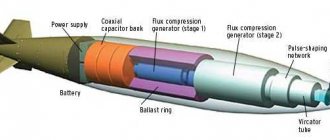
Electromagnetic pulse of a high-altitude nuclear explosion
The high-altitude tests began with the Americans, who on August 1, 1958 carried out the first explosion in the upper layers of the earth's atmosphere over Johnston Atoll in the North Pacific Ocean, 717 nautical miles from Honolulu (Hawaii). Launching from a launcher built on the atoll, the PGM-11A Redstone ballistic missile designed by Wernher von Braun raised a W-39 nuclear warhead to an altitude of 76.8 km. The charge had a power of 1.9 Mt in TNT equivalent. One of the results of these tests was the disruption of power supply in the Hawaiian Islands due to the effects of the electromagnetic pulse of a high-altitude nuclear explosion. Radio transmissions as far away as Australia were also disrupted. On August 12, a similar charge was lifted by an SS-51 rocket and detonated at an altitude of 42.98 km. These high-altitude explosions of powerful thermonuclear charges were intended to test the effectiveness of their use in missile defense (BMD). Immediately after this, in August–September 1958, the United States conducted a series of nuclear explosions directly in space.
A modified Tomahawk missile being launched from a ship during Operation Desert Storm
In 1959–1960 and until August 1, 1961, the USSR did not conduct nuclear tests, participating in a moratorium on nuclear testing together with the USA and Great Britain. Shortly after this moratorium was interrupted, on October 27, 1961, the Soviet Union carried out two tests, the purpose of which was to test the effect of high-altitude and space explosions on the operation of radio-electronic systems for detecting missile attacks and missile defense. Both nuclear warheads were delivered to the explosion site using R-12 ballistic missiles launched from the Kapustin Yar test site. Two charges were detonated above the center of the experimental missile defense system at the Sary-Shagan test site - one at a 300-kilometer altitude, the other at a 150-kilometer altitude.
The generation mechanism of the considered nuclear EMR is the conversion of a small fraction of nuclear energy into electromagnetic energy with a radio frequency spectrum, which is performed in several intermediate processes. The first of these is the production of gamma radiation during the explosion. This gamma ray then interacts with atmospheric gas molecules, producing electrons and positive ions. When charges separate, part of the gamma radiation energy is converted into the kinetic energy of electrons, and their flow causes a current, which is associated with the emission of electromagnetic energy.
High altitude nuclear explosion
It should be noted that at this time (early 60s of the last century) the quantitative characteristics of nuclear EMR were insufficiently measured due to the following reasons:
- firstly, there was no control and measuring equipment capable of recording extremely powerful electromagnetic radiation, existing in millionths of a second;
- secondly, the electronic equipment of that time used electric vacuum devices that were little susceptible to the effects of EMR, which reduced interest in its study.
The creation of semiconductor devices, and then integrated circuits, especially digital devices, and the widespread introduction of these means into radio-electronic equipment forced military specialists to reassess the threat of EMP. The greatest danger is the stage of EMR growth, at which, in accordance with the law of electromagnetic induction, due to the extremely rapid increase in the current pulse, the induced voltage in various circuits can reach significant values (up to thousands of volts).
When exposed to the considered pulse overvoltages on radio-electronic and electrical equipment, the following may be observed:
- breakdowns of pn junctions in semiconductor devices;
- breakdowns of vacuum and gas-filled gaps;
- melting and breaks of current-carrying paths and resistive elements, places of soldering (welding) of wires due to thermoelectrodynamic stresses;
- device malfunctions;
- breakdowns of insulating materials that are irreversible and lead to complete failure of products (capacitors, cables).
Since the beginning of the 70s. last century, the issues of protecting weapons and military equipment from EMP began to be considered by the defense ministries of the great powers as having the highest priority. It should be noted that the effect of EMP is not selective in nature, as a result of which military and civilian systems that are not direct or indirect targets of a nuclear attack will be subject to strong EMP effects during a nuclear attack on distant targets. And above all, the use of nuclear weapons from the point of view of human morality cannot be explained and justified.
A. D. Sakharov
Nevertheless, the effect of electromagnetic radiation turned out to be so effective that the question immediately arose: is it possible to create a “clean” non-nuclear electromagnetic EMP weapon that is selective in nature, and ensure its precise delivery to the area of the target being hit?
Explosive magnetic generator EMP
Explosively pumped Flux Compression Generator (FCG) has proven to be the most mature technology available for the development of such non-nuclear electromagnetic bombs.
It is known that an explosion is a powerful source of mechanical and thermal energy. In 1951, the Soviet physicist Andrei Dmitrievich Sakharov, an academician of the USSR Academy of Sciences since 1953, expressed the idea of the possibility of converting this energy into the energy of a magnetic field, and he also proposed designs for sources of super-strong magnetic fields and electric currents based on rapid deformation explosion of current-carrying circuits. The possibility of explosive compression of an axial magnetic field was also discussed in a short article by Yakov Petrovich Terletsky, a professor at the Faculty of Physics at Moscow University, published in 1957. Explosive magnetic sources of this type were called MK (magnetic cumulation) generators.
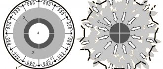
Rice. 2. Scheme MK-1
In the spring of 1952, R. Z Lyudaev, E. A. Feoktistov, G. A. Tsyrkov, A. A. Chvileva carried out the first explosive experiment in the USSR to produce super-strong magnetic fields. The diagram of such an axial magnetic field compression generator, called MK-1, is shown in Fig. 2. Inside the hollow metal cylinder 1 (liner), when capacitor bank C is discharged, a longitudinal magnetic field is created through the solenoidal winding 2. To ensure rapid penetration of the field into the cylinder, a narrow oblique cut was made in it, which subsequently slammed shut (not shown in Fig. 2). A charge of 3 explosives is placed outside the cylinder. A converging cylindrical shock wave is excited in this charge. To excite it, an electrical multipoint initiation system is used using detonators 4. The moment of initiation is selected so that compression of the cylinder begins at the moment of maximum current in the solenoid winding. In Fig. 2 also shows designations 5 and 6 - the sequentially studied sample and explosion products. Under the influence of a detonation wave, the cylinder is compressed at a speed exceeding 1 km/s. At the same time, its cross section decreases, and currents are induced in the walls of the cylinder-liner, tending to keep the magnetic flux constant. During the compression of the cylinder, work is done against the ponderomotive forces of the magnetic field, as a result of which the energy of the compressed field will increase. For ideally conducting pipe walls, the magnetic flux remains constant, and the strength and energy of the magnetic field increase in inverse proportion to the square of the inner radius of the cylinder.
Of course, in the real case there is a decrease in the magnetic flux. In experiments of this type, carried out in 1952, there is usually a decrease in flux by a factor of 2-3. In addition, at a certain value of the internal radius of the cylinder, its movement stops due to the counteraction of the magnetic field. Nevertheless, already in the first experiments with aluminum pipes of small diameter (about 100 mm), magnetic fields with a strength of 1 x 10⁶ Oe were obtained. Subsequently, in one of the experiments with a stainless steel pipe with a final diameter of the cylindrical cavity of about 4 mm, the value H was recorded , equal to 25 x 106 Oe. The advantages of the above explosive magnetic generator are the high density of magnetic energy on the axis with fairly uniform axial compression and simplicity of design. However, such a generator is only a magnetic field generator, which is not a current generator, since the azimuthal current in the cylinder is closed on itself and cannot be transmitted.
Rice. 3. Scheme MK-2
As mentioned above, an explosive magnetic high current generator was also developed by Sakharov and his employees and was named MK-2. In Fig. 3 and 4 show a diagram and photograph of the MK generator, and in Fig. 5 - stages of its work (a, b and c).
The MK-2 generator consists of a central conducting pipe 1 and a coaxially located external cylindrical spiral (solenoid) 2, which turns into a solid cylinder (glass) 3, the base of which is connected to the pipe. A long cylindrical charge of explosives is placed in the central tube, initiated using a CD primer at one point at the end on the spiral side. The electrical circuit of the MK-2 generator, formed by a pipe, a glass and a spiral, discharges a battery of capacitors. Under the influence of explosion products, the central tube is stretched in the form of a cone, and at the moment when the value of the discharge current passes through the maximum, its walls fly up to the beginning of the spiral. With further propagation of detonation along the pipe, the point of contact of the cone with the spiral moves along a helical line; the number of spiral turns remaining open decreases, and, accordingly, the inductance of the generator decreases. After the pipe walls approach the beginning of the glass, the generator turns into a coaxial. At the last stage of operation of the MK-2 generator, with sufficiently rapid continuous deformation of the pipe, the compression of the magnetic field occurs in a decreasing volume between the outer and inner walls of the coaxial. This process is accompanied by an increase in current through the electrical circuit and an increase in its energy. The increase in magnetic energy occurs due to the work done against the ponderomotive forces of the magnetic field by the walls of the central pipe.
Using the MK-2 generator, currents of 5 x 10⁷ A were obtained; in some experiments in 1953, the current reached 1 x 10⁸ A or more. In a magnetic field, it was possible to store energy of 1–2 x 10⁷ J. This energy was 10–20% of the energy released during the explosion of explosives located in the pipe inside the glass.
The consumer of electromagnetic energy is connected to the MK-2 generator using a transformer (the consumer is connected to the electrical circuit of the MK-2 generator by inductive interaction). This makes it possible to use the MK-2 generator for loads with significantly higher inductances. Experiments have shown that with the help of a transformer, a significant part of the magnetic energy obtained during explosive deformation of the circuit can be transferred to the consumer. For example, it was possible to remove 50% of the magnetic energy from the small-diameter MK-2 generator. This also opened up the possibility of creating a multi-stage MK system. In such a system, the magnetic energy obtained in the first generator is transferred to the second using a transformer, during the operation of which this energy is amplified and transferred to the third, etc.
Another method of transferring electromagnetic energy from the generator to an external load was also implemented - by breaking the electrical circuit with current under the action of an additional explosive charge and transferring the magnetic flux from the final part of the MK-2 generator to the load (using extra breaking currents). In this way, it was possible to transfer more than 50% of the energy generated by the MK-2 generator to an external active-inductive load. In a number of experiments, the time of energy transfer to the load was 0.5 x 10⁻⁶ s.
Rice. 4. Photo MK-2
For the sake of historical justice, it should be said that since 1952, the American physicist Clarence Maxwell Fowler was successfully developing an explosive magnetic generator at the Los Alamos National Laboratory (USA). It was created and demonstrated by him and his colleagues Garn and Kaird in the second half of the 50s. such a generator.
It is especially important to note the fact that the MK-2 generator, due to the physics of the process, generates a powerful electrical pulse, the frequency of which is below 1 MHz.
The next important step in the creation of electromagnetic weapons was the solution to the question of what exactly the pulses generated by these weapons should be, taking into account the specifics of their use for attacking distributed and concentrated objects.
K. M. Fowler
Coal dust
The first test of a vacuum charge was carried out in 1943 by a group of German chemists led by Mario Zippermayr. The principle of operation of the device was suggested by accidents in flour mills and mines, where volumetric explosions often occur. That is why ordinary coal dust was used as an explosive. The fact is that by this time Germany was already experiencing a serious shortage of explosives, primarily TNT. However, this idea was not brought to actual production.
In fact, the term “vacuum bomb” is not technically correct. In reality, this is a classic thermobaric weapon in which fire spreads under high pressure. Like most explosives, it is a fuel-oxidizer premix. The difference is that in the first case, the explosion comes from a point source, and in the second, the flame front covers a significant volume. All this is accompanied by a powerful shock wave. For example, when a massive explosion occurred in an empty storage facility at an oil terminal in Hertfordshire (England) on December 11, 2005, people woke up 150 km from the epicenter to the sound of glass rattling in their windows.
Requirements for EMO impulses
Electromagnetic weapons that use a pulse whose frequency is below 1 MHz can be called low-frequency. The use of this weapon will be effective when affecting power lines and communication lines, which will be induced by high-voltage voltage pulses.
In most cases, any cable wiring includes linear sections that are connected to each other at approximately right angles. Whatever the orientation of the weapon's electromagnetic field, there will always be more than one linear section of cable wiring oriented in such a way that a high efficiency of energy absorption will be achieved.
Rice. 5. Stages of operation of MK-2
Equipment connected to irradiated lines, namely power supplies and input devices of various systems, can be damaged by these high-voltage voltage pulses. In addition, powerful electromagnetic radiation can penetrate the target through the “front door”, namely through the antenna, the presence of which is typical for radar and communications equipment, and damage its electronic and electrical components.
High power electromagnetic pulse weapons operating in the centimeter and millimeter ranges have an additional mechanism for energy penetration into electronic and electrical equipment through ventilation holes and gaps between panels.
Any opening leading into the equipment allows a high-frequency electromagnetic field to form a spatial standing wave inside it (the equipment). Components located at opposite nodes of the standing wave will be exposed to a powerful magnetic field. Because high-frequency electromagnetic fields penetrate equipment more easily than low-frequency electromagnetic fields, and in many cases bypass protections designed to stop low-frequency energy from penetrating equipment, high-frequency pulse weapons have the potential to have greater lethality than low-frequency electromagnetic weapons.
Vircator
There is a wide range of high-power microwave devices: relativistic klystrons, magnetrons, vircators, etc. From the point of view of the possibility of using such a high-power microwave device in the development of electronic bombs and warheads, vircators were of significant interest, since they are capable of generating powerful pulses of energy, are structurally simple, and are small in size, durable and capable of operating in a relatively wide band of ultra-high frequencies (microwave).
The diagram of an axial type vacuum vircator is shown in Fig. 6, where 1 is the cathode, 2 is the insulator, 3 is the anode, 4 is the virtual cathode, 5 is the output window. In a vircator, negative potential is applied to the cathode and the anode is usually at ground potential. The fundamental idea behind a vircator is to accelerate a powerful flow of electrons through a mesh anode. A significant number of electrons will pass through the anode, forming behind it a cloud of space charge, the so-called virtual cathode VC, after which this device received the name “virtual cathode oscillator” (vircator).
Rice. 6. Vircator
At beam currents greater than the critical value for a given structure, the VC begins to oscillate. This process proceeds as follows:
- in the case when the “height” of the potential barrier created by the VC is greater than the kinetic energy of the incoming electrons, the electrons stop in front of the VC and turn around, which is equivalent to a displacement of the VC and the maximum space charge density towards the anode;
- In addition, the density increases rapidly, since almost all incoming electrons are captured by the virtual cathode moving towards the anode. As you approach the anode, the “height” of the potential barrier decreases and at a certain moment becomes less than the kinetic energy of the incoming electrons, which easily overcome the decreased potential barrier, moving from the anode behind the VC, which itself moves away from the anode. As a result, the VC moves until a potential barrier of sufficient “height” is restored, and then the process is repeated.
Moreover, the studies performed have shown that VC oscillations act as a certain disturbing force for beam oscillations around the anode between the cathode and the virtual cathode. All this taken together leads to the fact that the vircator makes it possible to generate powerful microwave oscillations with a fairly high efficiency. A powerful flow of electrons in the vircator is ensured by the use of a cold cathode operating in explosive emission mode. When the electric field strength is 5 x 10⁹ V/m and higher, field-electronic currents appear on the cathode with inhomogeneities in a vacuum, causing heating and explosion of the micropoints. Due to the explosion of many micropoints and due to the ionization of the cathode material, near-cathode plasma is formed, the front of which is the main emitter of the electron flow. The emission capabilities of such a plasma are very high, and it can provide an emission current density from the cathode exceeding 1010 A/cm2. Thanks to the use of explosive emission cathodes, it became possible to obtain electron beams with currents of up to 106 A.
When the explosive emission cathode operates, the resulting plasma moves towards the anode. Accelerated electrons hitting the anode cause the formation of near-anode plasma, which moves towards the cathode. Plasma cathode and anode torches, propagating towards each other, short-circuit the diode gap of the vircator in a time of the order of 1.0–1.5 μs. Therefore, the vircator generates a single pulse of electron current with a duration of several hundred nanoseconds to several microseconds. Typically, a vircator is built into a cylindrical waveguide structure. Power is typically coupled through a waveguide into a horn structure that serves as an antenna. He proposed using beams of relativistic electrons to generate electromagnetic oscillations back in the 40s. last century, outstanding Soviet and Russian theoretical physicist Vitaly Lazarevich Ginzburg, academician of the USSR Academy of Sciences since 1966, Nobel Prize laureate in physics 2003. However, only after the creation of the first high-current electron accelerators SEU in 1966–1967. A new promising direction began to take shape - high-frequency relativistic electronics. In the USSR, the most significant contribution to its formation and development was made by the Gorky (Nizhny Novgorod) school of physicists, headed by Andrei Viktorovich Gaponov-Grekhov, academician of the USSR Academy of Sciences since 1968.
On May 23, 1983, US President Ronald Reagan announced the Strategic Defense Initiative (SDI) program - a long-term complex of research and development work to create missile defense. The SDI program provided for the creation of active means of destruction of intercontinental ballistic missiles, including radio frequency electromagnetic weapons, based on new principles.
As for the vircator itself, a vircator based on a transit diode without an external magnetic field was proposed and experimentally implemented in 1985 at the Los Alamos National Laboratory (Los Alamos, New Mexico, USA). It had the following characteristics: P = 500 MW, f = 17 GHz, timp = 20 ns, efficiency. = 0.005. In 1987, at the Livermore National Laboratory. Ernest Lawrence (Livermore, California, USA) created a more powerful vircator (P = 4 GW, f = 6.5 GHz, t pulse = 40 ns, efficiency = 0.033).
In the USSR, in 1986, at the Research Institute of Nuclear Physics of the Tomsk Polytechnic Institute (NII YaF TPI), a vircator was created that had the following characteristics: P = 200 MW, f = 15 GHz, timp = 70 ns, efficiency. = 0.05, and in the same place in 1988 - another more powerful vircator: P = 2 GW, f = 5.5 GHz, tpulse = 30 ns. The most detailed study of the vircator in the USSR and in Russia was carried out at the Research Institute of Nuclear Physics TPI and at the Institute of High Temperatures of the Russian Academy of Sciences under the leadership of Andrei Nikolaevich Didenko, corresponding member of the USSR Academy of Sciences since 1984.
Vietnam experience
Thermobaric weapons were first used in Vietnam to clear jungles, primarily for helipads. The effect was stunning. It was enough to drop three or four of these volumetric explosive devices, and the Iroquois helicopter could land in the most unexpected places for the partisans.
Essentially, these were 50-liter high-pressure cylinders, with a brake parachute that opened at a height of thirty meters. About five meters from the ground, the squib destroyed the shell, and a gas cloud formed under pressure, which exploded. At the same time, the substances and mixtures used in air-fuel bombs were not anything special. These were ordinary methane, propane, acetylene, ethylene oxide and propylene.
It soon became clear experimentally that thermobaric weapons have enormous destructive power in confined spaces, such as tunnels, caves, and bunkers, but are not suitable in windy weather, under water and at high altitudes. There were attempts to use large-caliber thermobaric shells in the Vietnam War, but they were not effective.