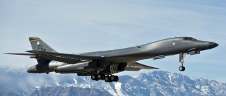
The General Dynamics F-111 long-range tactical bomber was the world's first production aircraft to incorporate the variable-angle wing concept. At maximum angle, the wings were practically adjacent to the tail stabilizer. There was a gap of 250 mm between the trailing edge of the wing and the leading edge of the tail.
The machine did not have an official name throughout its service life, and only in 1996 it began to be called Aardvark (anteater). The assignment of the name occurred at the time the F-111 aircraft was removed from service. Due to the high cost, the aircraft was practically not exported. Apart from the US Air Force, the vehicle was used only by Australia, where it was unofficially designated Pig (pig).
History of creation
In the late 50s, the US Air Force realized the need to create a replacement for the F-105 fighter-bomber that was in service. The requirements for the new aircraft were extremely contradictory - the aircraft had to carry a large bomb load and have a speed corresponding to a fighter.
Moreover, the military’s demands were constantly growing. As requirements changed, applicants for the order were eliminated. By 1962, only Boeing and General Dynamics were vying for production.
The initial design of the future F-111 aircraft was equipped with a fixed wing, but to ensure speed parameters, a variable-sweep wing was best suited, which was implemented on the aircraft. The use of such a scheme led to an increase in the cost of the aircraft and scared off a number of potential customers.
A novelty for its time was a radar station for monitoring the terrain.
Flying in this mode significantly reduced the likelihood of being hit by anti-aircraft fire. This continued until the advent of new types of weapons adapted to defeat air targets flying in terrain repeat mode.
The F-111A prototype flew in 1964, and mass production began three years later. Due to the high cost and problems with matching the profiles of the air intakes and the power plant, the volume of orders for the F-111A has decreased.
Vehicles of various modifications were used by the US Air Force until 1996. Australian vehicles lived longer - they were removed from service only in 2010. Some early American aircraft were converted into electronic warfare vehicles under the designation EF-111A. A total of 42 such aircraft were built.
Summary
Since writing the review on Valkyrie, for me this was the most difficult article in terms of studying the prototype and its hardware. Tommy's article, together with the Naval Fighters book, made it possible to partially unravel the intricate knot of materiel of the most little-known Anteater. The result of the review, whose writing and publication took more than 4 years, was a disappointing result. The Revell model, which at first seemed to be the only option for building a deck modification, turned out to be just a good old model of the early F-111A, made in the spirit of its time. If desired, you can cut out the first two or four YF-111Bs from it. The model is not of real interest today as an option and a basis for building any modification of the F-111. It is a historical artifact of modeling from half a century ago. Such models have their own price and their fans. They also have their own peculiarity - constantly changing owners. As an option, you can simply assemble it from the box in memory of modeling 48 years ago, and not engage in the empty task of sawing through history. Another result of the review was the study of an alternative possibility of optimally building the F-111B from a different model. And it became the Hobby Boss 1/48 F-111C model. A lot of aftermarket products have been produced for the 48th scale, including conversion kits that allow you to assemble the desired modification, including the YF-111B. This article is not an ideal review; there are many shortcomings and understatements in it, and there are still many white spots in the F-111B’s materiel. I just lifted the curtain for readers on the models and equipment of this aircraft. Perhaps someone will risk going down this path and the end result will be an interesting and entertaining model of the ancestor of the great Tomcat - the General Dynamics/Grumman F-111B TFX, the heaviest carrier-based aircraft in the world. I would like to express my gratitude to Pavel Pavel_P for providing the Revell model for review, and, of course, to Tommy H. Thomason for his research and work on the Y/F-111B materiel.
Design
The fuselage of the F-111 fighter-bomber is built according to a semi-monocoque design with a T-shaped power beam, which is the load-bearing element for the power plant.
Aluminum, steel and titanium-based alloys are used in the design of the fuselage power kit.
Machined aluminum panels are exemplary for lining caisson fuel tanks. The remaining areas are covered with sandwich panels made of aluminum sheet and honeycomb core.
The F-111 variable-sweep wing has a power set consisting of four spars. Mechanization includes slats and flaps. The kinematics of the flaps allows their deflection within a certain range of sweep angles.
The deflection mechanisms of slats and flaps are interconnected. Brake flaps are installed on the upper plane of the wing. A characteristic feature of the F-111 aircraft was the blocking of the flaps when the sweep angle increased beyond 26°.
The wing sweep of the F-111 aircraft changes smoothly within the range of 16-72.5⁰. Additionally, there are four fixed positions for takeoff, landing, maximum and cruise speed.
The hinges connecting the rotating part to the fixed part are located inside the structure and practically do not disturb the flat surface of the skin. The F-111 wing drive is hydraulic and controlled by two systems that duplicate each other. The adjustment mechanism does not allow you to set an asymmetrical angle.
The chassis is equipped with a nose and two main struts.
The design of the racks allows the F-111 to be operated from unpaved airfields. There are two wheels installed on the nose strut; cleaning is carried out in the direction opposite to the flight.
The main pillars are retracted into niches made between the air intake housings of the power plant. The main struts of the F-111 aircraft are mounted on a single console and operate from a single hydraulic cylinder.
The niche flap is equipped with a special drive that allows the flap to be used as an additional air brake.
The cockpit on the F-111 aircraft is equipped with two seats installed in parallel. The instrument panels are asymmetrical, the right side of the board is used for navigation and radar equipment. On the left side there are flight equipment and indicators of the power plant operating parameters.
Access to the cabin is through flaps on the canopy. The cabin has a special shield that automatically rises during a nuclear explosion. The shield protects the crew from the light and thermal effects of the explosion.
The F-111's controls are equipped with hydraulic boosters. To eliminate vibrations that occur during flight, an automatic correction mechanism equipped with an electro-hydraulic drive is used.
If an emergency occurs on board, the F-111 cabin ejects.
A parachute is used to reduce speed. An additional shock absorber that softens the impact upon landing is a pneumatic rubber cylinder.
The balloon provides buoyancy to the cabin when landing on the water surface. Shooting of the cockpit is allowed at low altitude or when the F-111 is immersed in water to a depth of 15 meters.
The fuel supply on the F-111 aircraft was located in caisson tanks located in the moving part of the wing console, as well as in a separate keel tank and two additional tanks installed in the fuselage. The fuselage tanks are located in the middle part and in the tail above the power plant.
The tanks are capable of holding 19021...19052 liters of fuel (depending on the model). The tanks are refilled centrally through the neck located in the area of the left air intake.
The F-111 aircraft is equipped with an in-flight refueling system, which is carried out through a special boom. The boom is mounted on top of the aircraft behind the cockpit canopy.
To increase the flight range of the F-111, external fuel tanks were used, which were installed on six pylons under the wings. There were two types of tanks, differing in size and capacity (1700 and 2270 liters, respectively).
The power plant of the F-111 aircraft consists of a pair of Pratt & Whitney model TF-30P turbojet engines equipped with an afterburner.
Depending on the modification of the F-111 aircraft, the engines have a nominal thrust of up to 79.6 kN and a thrust of up to 112 kN in afterburner.
The engine is built on a two-shaft design. On one shaft there is a fan (depending on the modification, it has two or three impellers) and two compressors. The low-pressure compressor is equipped with six compression stages, the high-pressure compressor with seven stages.
On the second shaft there is a high-pressure (one stage) and low-pressure (three stages) turbine. In front of the turbine there is an annular combustion chamber. The afterburner can be adjusted, providing five modes of thrust change.
| Motor housing diameter, mm | 1245 |
| Total length, mm | 6139 |
| Weight, kg | 1807…1816 |
| Air pressure increase rate | 19,8…21,8 |
| Temperature of compressed air in front of the turbine, C° | 1124…1176 |
The spin-up of the compressor and turbines to start the first engine is carried out with compressed air supplied from a ground source. The second engine is started with compressed air taken from the compressor of the running engine. In the absence of a ground compressor, starting is performed with a powder starter.
The F-111 air intakes were equipped with control cones and devices for cutting off the boundary layer of air flow.
Generators are installed on the distribution boxes of turbojet engines. The F-111 aircraft uses two 60 kW generators. Hydraulic pumps are also installed on the boxes, feeding two separate hydraulic systems.
Electricity consumers were avionics equipment, which included three radar stations. The stations provided terrain-following flight in automatic and manual mode.
The F-111 control system includes an autopilot that operates based on data from on-board radars and a radio altimeter. The antennas are located in the forward part of the fuselage, covered by a fairing.
The F-111's armament is located inside the fuselage and on the pylons. The fuselage has a special compartment 4900 mm long, located between the installation points of the nose and main landing gear. Six pylons are installed on the wings. The pylons were divided into fixed (four external) and movable (two internal).
When setting the wing to a sweep above the minimum, the outer pylons were automatically disconnected from the plane. The inner ones rotated with the wing, ensuring parallelism to the flow and reducing drag.
The F-111's weapons are controlled by an on-board system equipped with an infrared direction finder and a target detection and tracking radar.
The pylons could accommodate aerial bombs of the M117A1 type weighing 340 kg, cluster bombs of the GBU-58 model, high-explosive aerial bombs Mk-82 or 83 (weighing 900 and 1350 kg, respectively). The F-111 bomber could carry laser-guided bombs as well as glide bombs.
The pylons made it possible to place Sidewinder-type guided missiles, which were used for self-defense. The fuselage compartment allowed the placement of atomic bombs or was used to install reconnaissance equipment. The F-111's additional armament was the M61 Vulcan six-barreled revolving cannon.
Resin
- 0472 Verlinden 1/72 General Dynamics F-111D/F update set (for Hasegawa) – resin cockpit with etching will come in handy
- Crew 1/72 wheels F-111 – not suitable for modification of F-111B, not currently available.
- Combustion chambers from F-14 nozzles
- Resin conversion kit from SB Castings 1/48 #9601 containing the YF-111B nose cone, tail fin from the first 4 YF-111Bs, landing hook with fairing and 4 missile pylons.
- Resin conversion kit from Fox 3 Studios 1/48 - YF-111B nose cone, wing tips, main landing gear wheels, landing hook, tail boom fairings.
- Resin conversion set from Scaledown 1/48 #48022 F-111B conversion set
- Resin set from Scaledown 1/48 #48001 – F-111 Long Wing/Flap/Slats Set (to suit F-111B/C/G/FB-111A)
Etching:
- 72-073 Eduard 1/72 F-111E Aardvark (for Hasegawa) – wing mechanization, small things, old kit, extremely rare nowadays
- 72-074 Eduard 1/72 FB-111A Aardvark (for Hasegawa) – wing mechanization, small things, old kit, now extremely rare
- 72-075 Eduard 1/72 EF-111A Raven (for Hasegawa) – wing mechanization, small items, old kit, extremely rare nowadays
- SS175 Eduard 1/72 F-111D/E Aardvark (for Hasegawa) – useful only for small things – antennas, some cockpit parts and external small things.
- 72172 Flightpath 1/72 F-111 Aardvark/EF-111A ladders x 2
Modifications
The first production modification was the F-111A bomber, built in the amount of 160 copies. The first 30 vehicles were equipped with the TF30-P-1 power plant, the rest were equipped with the improved TF30-P-3 with increased traction. Several early vehicles did not have an ejection cockpit and were equipped with ejection seats.
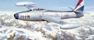
For the needs of the fleet, a version of the F-111B fighter was built, largely unified with the land version.
The naval aircraft had a shortened nose section with the ability to tilt upward. This feature made it possible to place the vehicles on the flight decks and hangars of aircraft carriers.
Due to the more severe conditions of takeoff and landing, tires with increased operating pressure were used. The wing consoles were equipped with additional tips. The radar equipment installed on board varied greatly.
In total, from 4 to 7 F-111B aircraft were assembled. The customer refused to build the machines due to the significant excess weight (almost 9,000 kg).
By order of Australia, the F-111C variant was built, which is a combination of solutions from the F-111A fighter and the FB-111A strategic bomber. The aircraft was equipped with eight external weapon suspension points. The total weight of weapons could reach 14,300 kg.
In 1970, the modernized F-111D fighter-bomber appeared, equipped with improved engines and new on-board electronics.
A total of 96 cars of this version were assembled, which served until 1993.
Problems that arose during the fine-tuning of the electronics led to the creation of the F-111E version, which was an F-111A model with air intakes from modification D. General Dynamics Corporation built 94 aircraft of this model.
Due to the high cost of the new electronic equipment used on the F-111D, it was decided to create a simplified version under the designation F-111F. The aircraft were equipped with a new modification of the TF30-P-100 engine. A total of 106 vehicles were built.
Another option was the F-111G, built on the basis of airframes left over from the UK's refusal to purchase a batch of the F-111K (a special version for the United Kingdom).
On the basis of the fighter-bomber, the FB-111 strategic bomber was produced, which was distinguished by a fuselage extended by 640 mm, which made it possible to increase the fuel supply on board, and elongated wing consoles from the naval vehicle. A total of 77 vehicles were assembled, some of which were subsequently converted to the F-111G standard.
Fuselage
The back of the fuselage is too flat in the area of the wing axes. The relief of the back in the engine area is not entirely accurate. This can be seen from the photo of the model and the aircraft. According to the MK and Bunrindo drawings, the center section is narrowed by 2 mm in the segment between the axes of rotation of the consoles and the stabilizer. According to the Detail&Scale drawings, the fuselage, on the contrary, is 5 mm longer between the nozzles and the wing rotation axes and has no width problems. According to the PKL drawings, the center section is narrowed by 1 mm and is 6 mm longer. The rear hump and its relief are less pronounced on the model. This can be seen from the drawings. The nose part in the area of the cockpit and the radar fairing does not have quite the correct sections - it is too square in the area of the instrument visor. The nose cone is of the wrong shape. It does not correspond in geometry to the fairing of the early and late types - it is 2 mm shorter than the early one, and 9 and a penny of millimeters shorter than the later one, which was on the aircraft with tail number 152714. When viewed from above, the nose fairing is very narrowed. The nose cone for the F-111A fits the drawings well, except that it is a little fuller at the front. The canopy and the hump on the fuselage behind it correspond more to the 5 first Y/F-111B and F-111A aircraft than to the 2 pre-production F-111Bs. The hump itself on the model is too flat. The tail fin between the nozzles is closer in shape to the first four Y/F-111Bs and the early pre-1967 F-111As, but the top and cutouts are incorrect. Therefore, it is quite difficult to make a pre-production F-111B from this plastic.
Performance characteristics in comparison with competitors
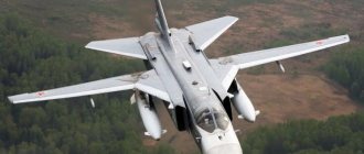
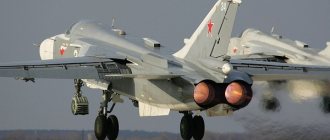
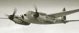
Due to its design, the F-111 has no direct competitors. The only aircraft with similar characteristics is the Soviet front-line bomber Su-24. Sometimes the Tu-22 bomber is compared to the F-111, but this comparison is not correct, since the Soviet machine is twice as large.
| Parameter | F-111E | Su-24M |
| Length, mm | 22 400 | 24 594 |
| Height, mm | 5 220 | 6 193 |
| Wingspan, mm | 19 200 | 17 638 |
| Empty weight, kg | 21 394 | 21 200 |
| Take-off weight, kg | 37 577 | 32 300 |
| Maximum weight, kg | 45 359 | 39 700 |
| Speed max., km/h | 2 655 | 1 700 |
| Ceiling, m | 17 985 | 11 000 |
| Rate of climb, m/s | 131,5 | No data |
| Crew, people | 2 | 2 |
The Su-24 bomber is equipped with unregulated air intake ducts and can only carry weapons externally.
The combat load of Soviet and American aircraft is approximately the same.
Specifications (F-111B pre-production)
F-111B, BuNo 151974, at NAS Moffettfield, California during field testing in the flight control wind tunnel
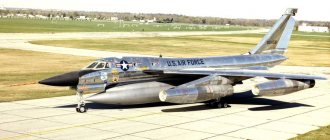
First experimental F-111B 152714
in storage at Davis Monthan AFB in 1971
For pre-production aircraft #6 and #7:
Data from
Thomason, Miller, Logan
General characteristics
- Crew:
2 (pilot and operator weapon system) - Length:
68 ft 10 in (20.98 m) - Span: Spread:
70 ft (21.3 m) - Swept:
33 ft 11 in (10.34 m)
15 ft 9 in (4.80 m)
- Spread:
655.5 ft² (60.9 m²)
550 ft² (51.1 m²)
NACA 64-210.68 root, NACA 64-209.80 tip
46,100 lb (20,910 kg)
79,000 lb (35,800 kg)
takeoff weight: 88,000 lb (39,900 kg)
2 × Pratt & Whitney TF30-P-3 turbofans
- Dry thrust:
10,750 lbf (47.8 kN) each
18,500 lbf (82.3 kN) each
Play
- Mach 2.2 (+1,450 mph, 2,330 km/h)
- Range:
2,100 miles (+1830 NMI, 3390 km); with 6 AIM-54 missiles and 23,000 pounds of fuel internal - Ferry Range:
3,200 miles (2,780 NMI, 5,150 km); with 2 x 450 gallon external tanks - Ceiling:
65,000 ft (19,800 m) - Rate of ascent:
21,300 ft/min (108 m/s) - Wing load: Spread:
120 lb/ft² (586 kg/m) - Swept:
144 lb/ft² (703 kg/m²)
0,47
weapons
- Weapons:
1 × M61 Vulcan 20 mm (0.787 in) Gatling gun (rarely installed) - Hardpoints:
6 underwing ammunition pylons and external fuel tanks - Missiles:
6 x AIM-54 Phoenix long range air-to-air missiles (four under wings, two in weapons bay)
Avionics
AN/AWG-9 - pulse Doppler radar
Combat use
F-111 aircraft entered combat within a few months of being put into service. The first battlefield was Vietnam, where two or three vehicles were lost. Due to losses and identified problems with the wing folding mechanism, the aircraft were withdrawn from active combat operations.
The vehicles were re-entered into battle at the end of the Vietnam War. 54 aircraft took part in the battles, with losses amounting to 6 aircraft.
>In 1986, F-111F aircraft were used during a raid on the residence of M. Gaddafi (Libya).
The strike was carried out from air bases in Great Britain. As a result of the attack, two aircraft were lost (one made an emergency landing, the second went missing).
The second major combat episode in the F-111's career was Operation Desert Storm. It involved 20 Model E vehicles, which were used to drop unguided bombs. There are no official data on losses.
More advanced F-111Fs, equipped with guided weapons, were used more actively and completed 2,500 combat missions. According to official data, five planes were shot down.
Decal
The decal is ancient. The substrate has already turned yellow and is cracked in some places. She herself encircles the decal elements with a reserve. There are color shifts on small OZs. You can't ask much from an old decal, so let's move on to painting options. The decal is offered in 3 options: Option No. 1 – F-111B, VF-101 “Grim Reapers”, bu/no 152714, AD/124, s/n A2-06
The option is pure “What If”.
The plane did not fly any “Grim Reapers” and did not wear any “tail codes” on the fin. Moreover, the location of the tactical number on the wing raises a lot of questions. The inscription NAVY should be along with a red marker marking the boundary of the first row of turbine or compressor blades. The Danger markings on the EO are incorrect. The red triangle must not extend to the rear red line. Option No. 2 – F-111B, VF-121 “Pacemakers”, bu/no 152714, NJ/105, s/n A2-06
Again, pure “What If”.
In the trash... I am attaching a photo of this aircraft from the literature. Option No. 3 – F-111A, USAF, s/n A1-26, bu/no 65-5708
This is one of the first F-111A, from the second series (26th F-111A including pre-production ones). The aircraft had a short flying career and was sent to Davis-Montan in 1971, where it remained until 1997, being dismantled for spare parts for other F-111s. The decal keel code is incorrect. The camouflage itself is not entirely correct - the location of the spots does not match the photo, in particular on the keel. What's the result? The tail number for the first two options corresponds to the 6th aircraft - the pre-production F-111B, which had a specific geometry that had little in common with this model. But more on that later. The decal is definitely in the trash. It is yellow, with incorrect keel codes and designations. There are no small symbols or signs. For modification B, it will not be difficult to remove the side numbers from other decals, taking the NAVY inscription from the same Phantom or Tomcat.
Interesting facts and traces in history
Over the years of operation, out of 563 F-111 aircraft built, 123 aircraft were lost.
Initial calculations showed the cost of the F-111 in the region of 3.7 million dollars per copy. Constant improvements and improvements led to an increase in the development budget to $2 billion.
The first deliveries began at a price of $18.7 million per aircraft, which led to a reduction in production plans by three times.
The F-111 development program was the largest since the end of World War II.
The F-111, despite its rather controversial career, became a springboard for the creation of a more advanced F-14 Tomcat with a variable geometry wing. However, the successor did not gain much fame - out of 712 cars built, at least 166 copies were destroyed in accidents.
Airplanes on display
Australia
F-111C
- A8-109 – Historic Aircraft Restoration Society, Albion Park
- A8-113 – Aviation Northern Territory Historical Society, Darwin
- A8-125 – RAF Museum, Point Cook, Victoria (preserved))
- A8-126 – RAF Center Amberly Kincaid, KLD
- A8-129 – Queensland Aviation Museum, Caloundra
- A8-131 – Moorabbin Aviation Museum, Wiki (cockpit module only)
- A8-132 – Ardagh, RAF Edinburgh, SA
- A8-134 – South Australian Museum Aviation, Port Adelaide, SA
- A8-135 – Caboolture Museum Combat Aircraft, KLD (cockpit module only)
- A8-136 – RAF Center Amberley Kincaid, KLD (cockpit module only)
- A8-138 – RAF Amberley, KLD (gate guard)
- A8-140 – Royal Australian Air Force Association Museum, Bull Creek, WA (cabin module only)
- A8-141 – RAF Center Amberley Kincaid, KLD (cockpit module only)
- A8-142 – RAF Wagg, New South Wales (gate guard)
- A8-147 – Evans Head Memorial Aerodrome Heritage Aviation Association, NSW)
- A8-148 – Fighter World, Williamtown, NSW