Preparing the mortar for checking the zero aiming line
Before checking the zero aiming line, it is necessary to level the mortar in the transverse direction, for which you should:
— install the mortar, if possible, on a flat area, giving it an elevation angle of 63°;
- wipe the control platform on the barrel and install a previously checked control quadrant on it (perpendicular to the axis of the barrel bore along the transverse mark on the platform); set the zero division of the quadrant scale to the pointer;
— bring the quadrant bubble to the middle using a clamp and a precise leveling mechanism.
On the drum 4
5
scale with one hundred divisions is fixed. Every tenth division of the scale is marked with a number (from 0 to 90 inclusive). The price of one division of the drum scale is one thousandth (0-01).
One full turn of the drum 4
rotates the body
15
of the sight in the vertical plane by one division (1-00) of the scale
27
.
There is a fixed pointer opposite the drum scale 13
, which serves to count divisions on the drum scale.
When setting the scale 27
of the elevation angle mechanism to division “10”, and the scale
4
of the drum to division “0”, after the lifting mechanism brings the longitudinal level bubble to the middle, the mortar barrel will be given an elevation angle of 45°, corresponding to the greatest firing range.
Transverse level 23
, mounted on the body
15
of the sight, serves to level the sight.
The sight is inserted into the hole of the bracket with an axis 26
and is secured in it by turning the handle.
On the front wall of the case 15
are engraved: the name of the sight (MPM-44), the manufacturer's brand and the number of the sight.
The ampoules of the levels are luminous. To protect against damage, they are closed with rotating rings with windows that open only when working with the sight.
The MPM-44 sight is stored in a case with a shoulder strap.
13. SIGHT MPM-44M
Since 1956, the modernized MPM-44M optical mortar sight, K-1 gun collimator and Luch-PM2M lighting device were introduced.
The difference between the MPM-44M optical mortar sight and the MPM-44 sight
The MPM-44M optical mortar sight (Fig. 32) is an MPM-44 sight, to which the following changes have been made in order to improve its performance:
1. A tide is introduced on the visor body 1
with a window to illuminate the reticle, which allows you to work with the sight at night.
2. A second transverse level 6 is installed on the sight body, which is used to work with the sight if the aiming point is located behind the mortar.
3. A special reticle is installed in the sight's sight, which ensures operation of the sight with the K-1 collimator, which serves as a universal aiming point.
4. A corrugated eyecup has been introduced, which makes it easier to work with the sight in a gas mask and increases the strength of the eyecup during operation.
5. Restrictive screws have been introduced under the levels, protecting the levels from turning around and allowing for precise installation of spare levels.
6. The handwheels of the protractor and the elevation angle mechanism are secured with nuts, which reduces the time of sight alignment.
A
b
Rice. 32. Sight MPM-44M ( a
- back view;
b
- front view):
1
— tide window illumination of the grid;
2
— corrugated eyecup (
17
);
3
- first transverse level (
Sb11
);
4
— nuts for fastening the handwheels of the angular and sighting mechanisms (
9
);
5
— bracket for the sight cover;
6
- second transverse level (
Sb12
);
7
- screws limiting rotation of the level (M0.4×5 with head)
7. Sight lighting has been introduced to illuminate the reticle, scales and sight levels in low visibility conditions; The lighting is mounted on the bracket of the sight cover.
8. Caps have been introduced onto the objective and eyepiece parts of the viewfinder, protecting optical parts from damage.
Otherwise, the MPM-44M sight is no different from the MPM-44 sight.
Weapon collimator K-1
The MPM-44M sight works in tandem with the K-1 gun collimator (Fig. 33), which is a universal aiming point.
The description, rules for handling the collimator and the method of aiming the sight at the collimator are given in the Service Manual - Gun Collimator K-1.
Luch-PM2M regimental mortar lighting device
When shooting in conditions of reduced visibility (at night, in fog, etc.), three special devices are used to illuminate the sight, the commander’s and equipment’s workplaces (Fig. 34).
Commander's device
The commander's device (Fig. 35) is designed to illuminate the commander's workplace during recordings, calculations and when checking sight settings on a mortar. The device consists of a wire 1
with a socket and a chip, a bracket
2
, a reflector
3
, a lamp
4
, a box
5
with batteries and a belt
6
for carrying the battery.
Bracket 2
is attached to the shoulder belt using a spring and can move along it. When the switch located on the battery box is turned on, the beam of light reflected by the reflector falls obliquely downward.
Rice. 33. General view of the K-1 collimator on a tripod with night lighting
Senior outfitter's device
The senior equipment operator's device (Fig. 36) is designed to illuminate the fuse installations.
The device consists of a wire 1
with a cartridge and a chip, a reflector
3
blue light
lamp
4 8
, a box
5
with batteries and a belt
6
for carrying the battery.
The base 8
has a loop
7
for putting on the index finger of the left hand and a strap
9
for attaching the base to the hand.
On the front side of the base there is a bracket 2
3
with a socket and a blue light lamp
4
is inserted and secured .
Rice. 34. General view of the Luch-PM2M lighting device with the lid of the storage box open
Rice. 35. Commander's device:
1
- wire with socket and chip;
2
— bracket;
3
- reflector;
4
- lamp;
5
— box with batteries;
6
- belt
Rice. 36. Senior loader's device:
1
- wire with socket and chip;
2
— bracket;
3
- reflector;
4
— blue lamp;
5
— box with batteries;
6
and
9
— belts;
7
- loop;
8
- base
Sight illumination device
The device for illuminating the sight consists of a wire branched into two branches with cartridges, a light cable and a box with a battery.
The cartridge illuminating the reticle of the viewfinder has a window through which the light beam passes, and a latch for attaching the cap to the boss of the viewfinder body. The light guide has slits through which the light beam passes and illuminates the scales and levels of the sight.
Note
. One battery is designed to illuminate the K-1 collimator.
Box for storing lighting fixtures
The lighting device, accessories and spare parts for them are placed in a special wooden box (see Fig. 34). The box has a tension lock and a shoulder strap with a buckle for carrying the box over the shoulder. The presence of special sockets, partitions and clamps guarantees the reliability of lighting devices in the box. Place items in the box according to the list attached to the inside of the box lid.
Alignment of the MPM-44 sight (MPM-44M)
The sight levels were not verified in the troops, since they cannot be adjusted in any way under military conditions.
To align the sight, you must select an aiming point (tree, pole, pole, etc.) located at a distance from the mortar of at least 400 m.
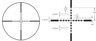
If it is impossible to select an aiming point at a distance of at least 400 m in front of the mortar, then you can make a sighting fan using a special shield, which should be placed in front of the mortar at a distance of at least 10 m, without removing the mortar from the firing position. To do this, you need to draw two brightly visible parallel lines, each 200-250 mm long and 3-5 mm wide, on a piece of plywood board, wall or bottom of the box.
The distance between the lines should be 136 mm. On a light background, lines should be drawn with dark paint (black, blue or charcoal). On a dark background, lines should be drawn with white paint or chalk.
Place the shield in front of the mortar so that the lines on the shield are vertical (check the installation of the shield using a plumb line).
After selecting the aiming point or installing the shield, aim the mortar barrel roughly by eye at the aiming point or shield. In this case, the slab and biped must be placed on the ground in such a way that during further work at the mortar they do not change their position. Therefore, it is most advisable to align the sight without removing the mortar from the firing position; The barrel must be securely secured in the shock absorber cage so that the white line on the barrel is not pushed to the side when looking at the barrel from behind.
Align the sight in the following order
Alignment of elevation angle scales
Give the mortar barrel an elevation angle of 63° with the greatest accuracy along the control quadrant, carefully installed on the control platform of the barrel.
Bring the transverse level bubble to the middle (using the sight leveling mechanism).
Then, rotating the drum, bring the longitudinal level bubble to the middle. In this case, the indicator line should coincide with the “7” mark on the scale, and the “0” of the drum scale should coincide with the pointer line. If the position of the scales does not correspond to the specified, then it is necessary:
— unscrew the four screws one turn and, holding the drum with one hand, turn the scale with the other until the zero division aligns with the pointer and screw the four screws in completely; at the MPM-44M sight, the blind nut securing the drum is unscrewed and screwed in accordingly;
— unscrew the locking screw one turn and the indexer locking screw two turns, move the index until its marks line up with the “7” mark on the scale, then screw both screws in completely.
To avoid friction, check for the presence of an end gap between the pointer and the scale; the gap must be at least 0.15 mm.
Alignment of the zero line of sight
Behind the mortar, at a distance of 10-15 m from it, install the compass so that the line of sight from the compass to the aiming point (or the right line on the shield) passes approximately through the middle of the ball heel of the breech of the mortar being tested.
Then, by rotating the compass monocular and working with the rotating mechanism of the mortar, align the white line on the mortar barrel and the aiming point (or the right line on the shield) with the vertical crosshair line in the compass monocular. The bubbles of the longitudinal and transverse levels should be in the middle.
By rotating the drum, align the vertical line of the crosshair of the sight mounted on the mortar with the aiming point (or the left line on the shield). In this case, the pointer line should coincide with the “30” mark on the protractor’s large division scale, and the pointer line should coincide with the “0” division on the protractor’s small division scale.
If the position of the scales does not correspond to the specified one, then it is necessary to loosen the locking screws securing the scale of large divisions of the protractor by half a turn and move this scale until the division “30” aligns with the pointer stroke, after which screw the screws until they stop.
Then loosen the four screws on the drum by one turn and, holding the handwheel with one hand, turn the scale with the other until the zero division aligns with the pointer, after which tighten the screws until they stop (in the MPM-44M sight, respectively, unscrew and screw in the blind nut securing the drum). Check whether the aiming of the mortar or sight has weakened.
Note: If there is no compass, then aiming the white line on the mortar barrel at the aiming point (or the right line on the shield) can be done using a sight mounted on the second mortar behind the mortar being tested at a distance of 10-15 m, or a plumb line suspended behind the mortar at distance 3-5 m).
Check the swivel level in the following order: give the mortar an elevation angle of 63° (along the quadrant) and accurately orient the swivel using the precision leveling mechanism along the transverse level of the sight, while the swivel level bubble should be in the middle.
If the swivel level bubble is not in the middle, then loosen the fastening screws, turn in one direction or the other and bring the bubble to the middle, then secure the level again with the fastening screws.
Note: 1. If the mortar has a sight swing mechanism, then before adjusting the level of the swivel it is necessary to align the marks on the swing mechanism clamp. 2. If coordinated with the sight level at an elevation angle of the mortar of 63? the level of the swivel moves away from the middle when the elevation angle of the mortar changes (within the limits of the operation of the lifting mechanism by more than 0.5 divisions of the level), then you cannot use this level of the swivel; in this case, when aiming the mortar, use only the sight level.
Checking the sight stand
After checking the sighting devices, it is necessary to check the stand attached to this mortar and determine the error of the stand. To determine the error of the stance, you need to mark at any aiming point with a sight mounted on a mortar without a stand, then mark at the same aiming point with a sight mounted on a mortar with a stand and determine the difference in marks both by the protractor and by the elevation angle. To determine the difference in marks by elevation angle, you need to use the sight's elevation angle drum to bring the bubble of the longitudinal level to the middle and. subtract its reading from the obtained elevation angle scale reading before installing the sight on the stand. This difference will be the error of the stand (without taking into account the measured strokes of the sight) in the elevation angle.
A stand error of no more than 0-05 is allowed (by protractor and elevation angle). The actual error of the rack must always be taken into account when working with it. If the rack error exceeds 0-05, then the rack must be taken to a workshop.
Collimator sights. Part 3: USSR. Collimators in aviation, artillery and small arms
The Soviet Union was one of the countries that successfully developed, improved collimator sights and put them into service. First of all, collimators were used in aviation, then in artillery: they were installed on mortars, from the mid-20th century on howitzers, and were also used in anti-aircraft installations.
The content of the article
Collimator sights in aviation
One of the first aviation collimator sights was the PAK-1 sight.
PAK-1 on an I-16 fighter, 1936
Then the PBP-1 sight appeared...
...which was installed on Il-2 attack aircraft.
The PBP-1 sighting reticle is illuminated by a red LED, and in the original by an incandescent lamp, and, accordingly, should be yellow.
Again, an example of the action of a collimator.
Later, other CPs were developed, but the basic design of the aircraft sight remained the same.
Collimator sights in artillery
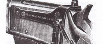
The next area of military application of collimator sights is artillery. Initially, in the 30-40s, collimators were used as mortar sights. These were MP-82 and MP-41.
MP-82 mortar collimator sight
The collimator is located on the rotating cover of the protractor mechanism. Thus, the collimator, goniometric mechanism and sight are one whole. The collimator and the goniometer mechanism, taken together, represent a simplified panorama that serves to guide the mortar to the target.
The collimator is used for sighting at the aiming point. It consists of a lens glued together from two lenses 1 and 1a (in the figure below). At the focus of the lens there is a plane-parallel plate 2 with a light slit. The light slit is a 0.05 mm wide slot in the silver layer covering the plane of the plate on the lens side.
MP-82 mortar collimator sight
Later, collimator sights on mortars were replaced by optical ones, which were more convenient. In the mid-20th century, collimator sights were added to artillery panoramic sights.
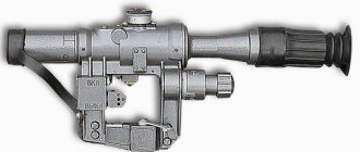
Sight K-1
The K-1 gun collimator is designed for horizontal aiming of a gun (mortar) in the absence of natural remote aiming points, as well as in conditions of poor visibility. K-1 is used for ground artillery guns and mortars. Each gun (mortar) is assigned one K-1. The K-1 can only be used in conjunction with the PG-1 panorama on guns and with the MP-46M or MPM-44M sights on mortars. When working with K-1 during the day, natural light is used to illuminate the reticle, and in poor visibility conditions, a rechargeable battery is used.
Anti-aircraft installations
At the end of the 30s of the 20th century, military designers came to the conclusion that in high-speed small-caliber anti-aircraft guns it would be advisable to replace the foreshortened sights with collimator sights, but the war made its own adjustments. Collimator sights became widely used in anti-aircraft installations after the war.
ZPU-2 (model 1944)
The K10T collimator sight was used as a ZPU-2 sight.
ZPU-1 (model 1948)
The ZPU-1 used a more advanced sight VK-4(M).
Scale of sights VK-4 and VK-4M.
The DShKM and KPVT tank anti-aircraft machine guns were fired using K10-T and VK-4 collimator sights, respectively.
ZU-23-2
ZU-23-2 uses the ZAP-23 sight...
Which includes optical and collimator sights.
Regardless of the type of collimator sights - aviation or anti-aircraft - one scheme was used.
It should be noted that collimator sights were widely used in the USSR; they were constantly developed and improved, but this primarily concerned aviation, air defense and artillery. Things were not so good with red dot sights for small arms.
Collimators for small arms in the USSR
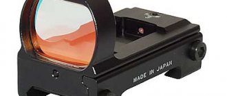
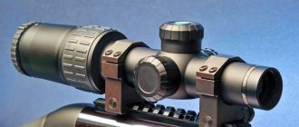
As I said, in the Soviet Union, collimator sights were used quite widely, but not in individual small arms. Around the end of the 80s, collimator sights for small arms began to appear. These were closed-type sights, with a red luminous dot as an aiming mark.
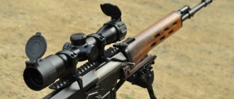
Sight "Firefly T-1"
The picture shows the Vyuga-45-2 collimator sights for Kalashnikov assault rifles (left) and the Firefly T-1 for hunting rifles (right).
For illumination in the daytime, ambient light was used, the aiming mark was red, and at night a tritium light element was used, the mark was green. A similar solution was found in the Armson OEG sight.
Initially, closed sights were called sights that did not have a transparent lens, but only projected an aiming mark into the shooter’s eye. The target was not displayed in the eyepiece, aiming was carried out binocularly when observing the aiming mark with one eye and the target with the other, a combination of images from both eyes, characteristic of binocular vision, occurred in the shooter’s brain.
However, the binocular vision of shooters may have various deviations from the norm. In some cases, these deviations manifest themselves in the form of hidden strabismus. With this lack of vision, a person may experience spontaneous deviations of the visual axes caused by the separation of visual images, which is a characteristic feature of “closed” sights. Also, hidden strabismus can manifest itself in a person under conditions of excitement, fatigue, under the influence of medications, etc.
In other words, the main disadvantage of “closed” type sights is that aiming with their help is less predictable. Therefore, such sights were abandoned by the troops. Just like in the US Army in the 70s, which I wrote about earlier.
Sights using light separation were developed.
The same principle was used in Weaver QuickPoint sights.
In the late 80s and early 90s, they began to develop open sights for both civilians and the military. It is interesting that, unlike military sights, civilian ones used electric batteries to illuminate the mark. This is understandable - batteries are in short supply, the sight’s operating life is short, and the LED’s operation is unreliable.
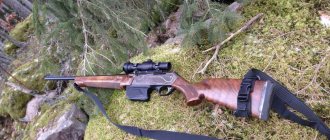
Collimator sight "Taiga", for use on hunting weapons.
Collimator sight “Rusak” from Kazan OMZ, for use on hunting weapons.
At that time, collimator sights also appeared for the military.
Sight "Zapev"
Sight "Thread"
These sights also used the principle of dividing the light flux. A tritium light element was used to illuminate the aiming scale at night.
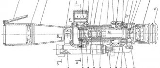
Optical design:
They functioned as follows:
The target is observed through protective glasses 1 and 3, a beam splitting mirror 2 and a switchable neutral density filter 11. The image of the aiming mark printed on the plate 10, after passing through a lens consisting of lenses 5, 6, is projected into the field of view using mirrors 4 and 2. In daytime conditions, grid 10 is illuminated by natural light (mirrors 8 and 9 are shifted down - switch position D). In twilight and night time, mirrors 8 and 9 are shifted upward (switch position H) and project light from source 7 onto the aiming mark. On the surface of the plane-parallel plate 10, located in the focal plane of the lens, a square, two short horizontal strokes and a long vertical stroke are applied, which are visible through transmission. The rest of the plate is covered with opaque varnish.
The sighting mark is similar to the “Thread” sight, day and night.
The “Thread” sight was further developed, several modifications of it appeared, the Internal Troops of the Ministry of Internal Affairs of the Russian Federation used it during the fighting in Chechnya, it was adopted by various units of the Ministry of Internal Affairs of Russia.
In fact, about the “Zapev” and “Thread” sights, it is difficult to say what type they are - open or closed. Soviet developers initially followed the path of using radioactive light elements; later, most collimator sights use this method of illuminating the aiming mark.
PS The article turned out to be meager due to the lack of materials. It is extremely difficult to find anything about Soviet collimator sights for small arms. Therefore, I ask you to complement it. And I especially want to know the Vyuga-45-2 sight.
Author - Sergey Zybin (solikama)
Continuation:
- Collimator sights. Part 4: Oxford Lightning Illuminated Gunsight and Single Point Collimators
Previous parts:
- Collimator sights: Operating principle, history and prospects
- Collimator sights. Part 2: Holographic Sight