For other uses, see Rocket launcher (disambiguation).
A portable device that launches an unharmed missile
| This article requires additional links for verification . |
An American soldier takes aim with an M1 Bazooka base.
Rocket
is a device that fires an unguided, rocket-propelled projectile, although the term is often used to refer to mechanisms that are portable and capable of firing actual missiles.
History[edit]
Main article: History of rockets
Rocket carts from
Wubei Zhi
Image of the "long snake" grenade launcher from
Wubei Zhi.
The earliest rocket launchers recorded in Imperial China consisted of arrows modified by attaching a rocket motor to a shaft a few inches behind the arrowhead. The rocket was propelled by burning black powder in the engine; they should not be confused with early fire arrows, which were ordinary arrows carrying small tubes of black powder as an incendiary agent that only ignited after the arrow had reached its target). The rocket launchers were made from wood, wicker and bamboo tubes. [1]The launchers separated the missiles with frames designed to separate them, and the launchers could fire multiple missiles at once. Textual evidence and illustrations of various early rocket launchers can be found in the 1510 edition of the Wujing Zongyao,
translated
by Needham
and others at Princeton University.
(The original Wujing Zongyao
was compiled between 1040 and 1044 and described the discovery of black gunpowder, but predated the invention of the rocket. Partial copies of the original survive, and the
Wujing Zongyao
was republished in 1231 during the Southern Song Dynasty, including military developments dating back to the original publication in 1044 British scholar, sinologist, historian Joseph Needham argues that the 1510 edition is the most reliable in its fidelity to the original and the 1231 version, since it was printed from blocks that were cut directly from the styles of the edition made in 1231 AD .)
The 1510 Wujing Zongyao [2] The text also describes a portable rocket launcher consisting of a belt and a bamboo tube. [3]
Rockets were introduced to the West during the Napoleonic Wars; The Congreve rocket was a British weapon invented by Sir Congreve in 1804 after Indian rockets emerged at the Siege of Seringapatam (1799). Congreve's rockets were launched from an iron chute about 18 inches (45 centimeters) long called a chamber
. [4] These cameras could be anchored to the ground for horizontal launch, mounted on a collapsible copper tripod for high-angle firing, or mounted on frames on carts or the decks of warships. [5]
During the American Civil War, both the Union and Confederate forces experimented with and produced rocket launchers. [6] Confederate forces used Congreve rockets in limited numbers due to their inaccuracies, while Union forces used Hale's patented rocket launcher, which fired seven to ten inch rockets with fins at a range of 2,000 yards.
World War II[edit]
World War II Katyusha grenade launcher mounted on a ZiS-6 truck.
Pre-war military missile research programs undertaken by many major powers led to the introduction of a range of missile and artillery systems with fixed or mobile launchers, often capable of launching multiple missiles in a single salvo. In the United Kingdom, solid rockets were initially used as anti-aircraft missiles; The 7-inch non-rotating shell was fired from single pedestal-mounted launchers on warships, and the 3-inch version was used by shore-based Z batteries, for which several "projectors" were developed. Later developments of these weapons included several Land Mattress launchers for surface-to-surface bombing and RP-3 air-to-ground missiles, launched from rails mounted on fighter-bombers. In Germany, the 15 cm Nebelwerfer 41 was an adaptation of the multi-barrel smoke mortar for artillery rockets. Soviet's Katyushas were self-propelled, mounted on trucks, tanks and even trains. The United States Army deployed the tank-mounted T34 Calliope system late in the war. [7]
Rocket artillery launchers
The article presents the results of an initial analysis of the technical development of rocket artillery launchers in the period from the 19th century to the present day in the world, including their classifications and definitions, with an emphasis on domestic developments. The article will be updated as information is processed.
The source base of the article consists of technical descriptions and albums of drawings for products, specialized periodicals and Internet resources, without which it would be impossible to create a wide illustrative part. At the same time, the author warns readers that if they go to the Internet resources indicated in the sources, some of them may not load over time, both due to technical problems and due to the deletion or blocking of site materials.
The study of this issue was carried out by the author as part of the preparation of a final qualifying work (GQR) (1999-2000) and a diploma project (2001-2002) while studying at Tula State University, preparing the book “Multiple launch rocket systems. Review" (end of 2004 - first half of 2006) and its updated version (2007-2014), preparation of a dissertation and a textbook under the working title "Rocket Artillery. Introduction to the Specialty" (2007-2014), teaching on which, regarding the introduction to the design of the components of multiple launch rocket systems, should be provided after reading to students (cadets, listeners) the course "Designs of machines and mechanisms" and using a specialized terminological dictionary on MLRS , prepared by the author of the article.
The article is intended for students of defense specialties of civilian secondary and higher educational institutions, cadets of military schools and institutes, students of military academies, engineers, researchers, analysts, database compilers, specialists involved in the identification of weapons and military equipment at the initial stage and all those interested in this question.
The author expresses gratitude to the management staff and staff of the museum, archive and scientific library of the Military Historical Museum of Artillery, Engineer Troops and Signal Troops (VIMAIViVS, Russia, St. Petersburg), staff of the Russian State Library (RSL, Russia, Moscow), Russian National Library (RNL, Russia, St. Petersburg), Scientific and Technical Library of JSC NPO SPLAV (Russia, Tula), Mikhailovsky Military Artillery Academy (MVAA, Russia, St. Petersburg) for assistance provided in the collection of information. The author also expresses his gratitude to the General Director of JSC NPO SPLAV (Russia, Tula) N.A. Makarovts and the administrator of the site “Rocketry” (Russia, St. Petersburg) Klochkov A.V. for the financial support provided.
The author’s analysis of the development of rocket artillery launchers in the above period in the world allowed us to establish that:
Rocket artillery launchers mean:
- combat vehicles (,,,,,,,
,,,
,,,,,). - launchers: towed (
,
,,,,
,
,,,,,). - portable (
,,,,
,,
,,
,
,). - railway (,,,).
- stationary: underground (
,,). - underground-ground (,
,,
,,,).
).
Classifications
Rocket artillery launchers, both in general and in particular, can be classified according to the following criteria:
By type of movement:
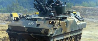
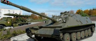
- self-propelled, which include combat vehicles, railway launchers, motorcycle launchers (PU) and buggy-mounted launchers.
- towed, which include launchers of rocket launchers on carriage chassis and on trailer chassis.
- portable, which includes portable launchers that can be disassembled for transportation in combat and training conditions.
- stationary, which include underground installations and underground-ground installations.
- stationary-mobile, which include launchers installed both on the ground and on a self-propelled base (in the back of trucks).
Based on chassis type, self-propelled launchers (combat vehicles) can be classified as:
- wheeled, i.e. the running parts of which are the chassis of trucks, wheeled armored personnel carriers (), motorcycles (,), buggies (fast attack vehicles) (,), combat reconnaissance patrol vehicles (,,), as well as railway platforms (,,,) (the latter are currently are not used).
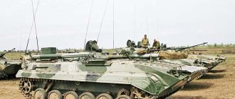
- tracked, i.e. the running parts of which are the chassis of tanks and tracked armored personnel carriers ().
- half-tracks, i.e. the front undercarriage is wheeled, and the rear is tracked (not currently used) (
).
According to the design and layout scheme, combat vehicles can be classified as:
- classic (two-component), i.e. with chassis and artillery unit (
). - combined (multicomponent), i.e. combining the design of a combat and transport vehicle () or a combat and transport-loading vehicle (
,,), as well as with several artillery units (,,)
Based on the type of auxiliary on-board equipment, combined combat vehicles can be classified as:
- with on-board automated loading equipment ().
- with a set of shelves arranged longitudinally (
,) in relation to the length of the chassis, and across (in the transverse position) (
).
Based on the type of guide package, combat vehicles can be classified as:
- with a permanent package, i.e. irreplaceable after firing and, depending on the design, reloadable either manually by crew numbers, or by means of a transport-loading machine.
- with a replaceable package, i.e. with transport-launch containers, depending on the type of which, it is either replaced after firing by means of an on-board crane of a combat vehicle or a transport-loading vehicle, or manually reloaded by crew numbers.
Transport and launch containers can be classified:
by type of sealing:
- unsealed, i.e. rechargeable at the factory with the ability to recharge without replacing the container in the field.
- sealed, i.e. loaded with projectiles and sealed in the factory. Reloading shells with crew numbers manually or using a transport-loading machine in the field is impossible. Only replacement of transport and launch containers is possible.
by type of use of basic materials:
- metal, i.e. the main structural elements are made of metals.
- metal-composite, i.e. in which the body is made of metal elements, and the guides are made of composite materials.
Based on the type of support, portable starting devices can be classified as:
- tripod.
- bipedal: without rear support plate ().
- with rear base plate ().
By type of application, towed launchers can be classified as:
- terrestrial, i.e. transferred to a combat position on the surface of the earth.
- onboard, i.e. installed in truck bodies. This method is intended to be used in extreme cases.
By type of development option, starting devices can be classified as:
- official, i.e. the development of which is carried out on the instructions of the Ministry of Defense or a foreign customer by specialists from specialized scientific and technical organizations with factories engaged in pilot production, and assembly is organized at official industrial enterprises in compliance with all technical control standards.
- unofficial (initiatively, in some cases over time with the transition to the level of official development), i.e. the development of which is carried out on an initiative basis by specialists from specialized scientific and technical organizations without receiving an official assignment from the Ministry of Defense or a foreign customer, as well as by self-taught people in technical fields of knowledge. The latter direction is inherent during combat operations.
Based on the type of production and repair option, starting devices can be classified as:
- industrial, i.e. assembly and repair are organized at official industrial enterprises or repair shops in compliance with all technical control standards (,).
- non-industrial, i.e. assembly and repair are organized in non-industrial conditions (for example, in garages, open areas) (,,).
In turn, industrial production samples can be classified as:
- licensed, i.e. production is organized with officially issued permission (license) from organizations of the developing country (or developing countries).
- unlicensed i.e. production is organized without officially issued permission from organizations of the developing country (or developing countries), as a rule, in the production of analogues of captured samples during combat operations.
Design features of starting devices
War vehicles
A combat vehicle is a type of rocket artillery weapon that includes a modified wheeled or tracked chassis of a vehicle on which the artillery unit is mounted.
Combat vehicles on modified truck chassis
Currently, combat vehicles on modified truck chassis are the main type of rocket artillery launchers. A relatively detailed description of the structural elements of only this type of rocket artillery launching devices can be given using the example of domestic models from the period of the Great Patriotic War to the end of the 80s of the twentieth century. Judging the structural elements of foreign combat vehicles of this type, as well as other types of launching devices, can only be superficial due to the lack of open detailed information.
The analysis of the designs of combat vehicles showed that throughout the entire world development, their two main parts are: the artillery unit (during the Great Patriotic War in the Union of Soviet Socialist Republics (USSR) it was called a throwing unit) and a specially equipped (modified) vehicle chassis, on which the artillery unit is mounted.
By equipping the chassis with special equipment (modification) we mean installing on it the equipment necessary for operating the combat vehicle after final assembly.
In general, the following modifications (i.e. equipping with special equipment) have been installed on the chassis for combat vehicles of different generations:
- modification of the chassis side members for attaching the subframe (base, lower machine) of the artillery unit (throwing unit) through various types of connections (by means of bolts, clamps or in combination with these two types of connections).
- equipping the cabin with protection (armoring) to protect it and the crew numbers located in it from the action of a gas jet of a projectile when fired, protection from fragments of the rocket chamber in the event of its rupture, as well as fire from small-caliber weapons and fragments of artillery shells.
- equipping with fastenings (brackets, brackets) for cabin protection, a gas tank for placing entrenching tools (shovels, crowbar).
- equipping the cabin with an intercom to transmit commands from the cabin.
- equipping the cabin with a bracket for a fire extinguisher, designed to localize small fires and in the event of a small engine fire. In the event of a severe fire, it is not advisable to extinguish the source or sources of fire, since the gas tank may explode and, if there is ammunition in its guides, detonation may occur.
- equipping an (additional) cabin to accommodate equipment for preparing a combat vehicle for firing, crew numbers and their personal property and weapons, life support devices, and communications equipment.
- equipped with protection for gas tanks and the gas sump from mechanical damage and the effects of a gas jet.
- equipped with a platform for mounting a spare wheel.
- equipped with footrests (right and left) for ease of climbing onto the equipped chassis. To prevent slipping, dots are welded onto the sheets of the running boards, as well as on the platform. You can use the drop-down side board as steps (stairs) (,,
). - equipping the seat behind the cockpit to accommodate the crew numbers of the combat vehicle.
- equipping under-seat drawers to accommodate alkaline batteries, remote reel, panorama, tools, spare parts and accessories.
- equipped with covering sheets to protect the installation from contamination - they covered the space between the chassis frame side members.
- equipping a frame with wings. The frame serves to attach the artillery part of the combat vehicle to the chassis side members and to attach the rear folding wings of the combat vehicle. The wings serve to protect the artillery unit and crew from dirt and dust when the combat vehicle moves.
- equipping the chassis with jacks to ensure leveling of the combat vehicle before firing, unloading the springs of the rear axles and imparting stability (reducing vibration) to the combat vehicle during firing.
- equipping electronic and electrical systems to ensure guidance and launch of missiles from the cockpit of a combat vehicle
The artillery unit is a structural part of a combat vehicle, which includes structural elements through which guidance and firing of ammunition and, if necessary, transportation of missiles are ensured, both with a fully charged package and a partially charged guide package.
The main structural elements of the artillery units of the main installations (combat vehicles) during the Great Patriotic War, which received the indices M-13, M-8-48 and BM-31-12, are presented in Table 1. For definitions of terms for structural elements, see after Table 1.
Table 1
| M-13 combat vehicle | Combat vehicle BM-8-48 | Combat vehicle BM-31-12 | |
| Base | |||
| Swivel frame | |||
| Swivel mechanism | |||
The main elements of the artillery unit are the base and the rotating part.
The composition of the artillery unit from bottom to top:
The base (or subframe - according to post-war terminology) is a structural element of the throwing installation (hereinafter referred to as the artillery unit in modern terminology) on which the artillery unit units were mounted. It also served to strengthen the chassis side members and distribute the load along their length and to mount the artillery unit on the vehicle chassis. The base was attached to the chassis using bolts and clamps or four bolts on each side.
The rotating frame is a structural element of an artillery unit that ensures the rotation of the main structural elements of the throwing system in the horizontal plane in a certain range of pointing angles. The rotation was performed using a turning mechanism. To perform the movement of the combat vehicle, the rotating part was locked using a mechanism for fastening the rotating frame in a stowed manner (or with a stopper for fastening in a stowed manner).
Rotating mechanism - a structural element of an artillery unit, designed to impart movement (rotation) to the rotating frame to ensure the setting of the azimuth angle (horizontal guidance).
A lifting mechanism is a structural element of an artillery unit, designed to impart movement in a vertical plane to a truss with guides in order to set the elevation angle.
A truss is a structural element of an artillery unit, attached to a rotating frame and serving as the basis for attaching a package of guides.
A package (or a package of guide cells) is a structural element of an artillery unit, consisting of guides attached to the truss, each of which is designed to give the initial direction of movement to rocket projectiles.
The main structural elements of the artillery units of the main post-war combat vehicles adopted for service in the 50s - 60s of the twentieth century, which received the indices BM-24, BM-14, BM-14M, BM-14MM, BMD-20 are presented in Table 2 For definitions of terms for structural elements, see after Table 2.
table 2
| BM-24 combat vehicle | Combat vehicles BM-14, BM-14M, BM-14MM | BMD-20 combat vehicle |
| Rotary mechanism (,) | ||
| () | ||
The subframe was a welded rectangular structure, which was the base of the artillery part of the combat vehicle, mounted on the side members of the vehicle chassis.
The stand was fixedly mounted on a subframe and served as a support for the rotating part of the combat vehicle.
The rotating frame, under the action of a rotating mechanism, rotated on a stand, on which it rested on three vertical rollers. Six horizontal rollers centered the rotation of the rotating frame and kept it on the stand from tipping over.
A worm-type rotary mechanism served for horizontal guidance of the guides in a certain range of guidance angles.
A screw-type lifting mechanism served to impart elevation angles to the guides in the horizontal firing sectors.
The balancing mechanism was spring-type, pushing type, and served to reduce the force on the handle of the lifting mechanism drive.
The lifting and balancing mechanism served to give the guides elevation angles and balance the swinging part.
The truss was a spatial welded structure. It was installed in the bearings of the rotating frame brackets and, together with the guides mounted on it, formed the swinging part of the combat vehicle.
A package of pipes (or a package of guides) is a structural element of an artillery unit, consisting of guides attached to the truss, each of which is designed to give the initial direction of movement to rocket projectiles.
Analysis of the data in Table 1 and Table 2 led to the conclusion that the main structural elements of post-war rocket artillery combat vehicles basically remained the same, only their design changed and, in some cases, their name changed. The base became known as a subframe. New structural elements have appeared - a cabinet and a balancing mechanism. In the design of the BMD-20 combat vehicle, the balancing mechanism was combined with a lifting mechanism and the new structural element became known as the lifting and balancing mechanism (later, a similar structural element was used in the designs of the 9A52 and 9A52-2 Smerch MLRS combat vehicles). The attachment of the subframe (base) to the chassis side members was identical.
The main structural elements of the artillery units of the main combat vehicles adopted for service from the early 60s of the 20th century to the end of the 80s of the 20th century, which received the indices BM-21, 9P140 and 9A52-2, are presented in Table 3. Definitions of terms for structural elements, see after table 3.
Table 3
| BM-21 combat vehicle | Combat vehicle 9P140 | Combat vehicle 9A52, 9A52-2 |
| () | Lower machine | |
| Shoulder strap | Shoulder strap | |
| Base (turning part) | Upper machine (, ) | (with all components mounted on it constitutes a rotating part) |
| Guidance Mechanisms | Lifting and balancing mechanism | |
| Swivel mechanism | ||
| (forty pipes, the cradle assembly and the balancing mechanism make up the swinging part) | The cradle (with all the components mounted on it forms the swinging part) (,
| (with all the units mounted on it, it makes up the swinging part) |
| Package (guides) | Package (guides) | Package (guides) |
BM-21 combat vehicle
The assembled frame serves as a support for the rotating part of the combat vehicle. The main parts of the frame assembly are the cross member and the frame. The frame has three support points: two front ones - on beams mounted on the chassis side members, and the third - in the transverse beam.
The shoulder strap is a bearing support for the rotating part of the combat vehicle. The fixed ring of the shoulder strap has teeth cut into it, with which the main gear of the turning mechanism meshes. The rotating ring of the shoulder strap is attached to the lower ring of the base, and the fixed one is attached to the frame assembly.
The base is a welded structure in which the combat vehicle components are mounted: electric drive equipment, guidance mechanisms, travel-locking mechanisms for the combat vehicle and some parts of pneumatic equipment. A ring is mounted at the bottom of the base, which attaches it to the shoulder strap. The base with all the parts and assemblies mounted on it constitutes the rotating part of the combat vehicle.
Guidance mechanisms serve to guide the combat vehicle's tube package in the vertical and horizontal planes within certain ranges of guidance angles. They are driven electrically or manually.
The balancing mechanism serves to partially balance the swinging part of the combat vehicle and is located in the cradle. It consists of two identical torsion bars - packages of steel plates that work in torsion. One end of the torsion bar is embedded in the cradle, and the second end is connected to the base by a system of levers.
The cradle is used to assemble a package of pipes on it and is connected to the base by two axle shafts, on which it rotates (swings) when aimed at the elevation angle.
A package (or a package of guides) is a structural element of an artillery unit, consisting of guides secured to the cradle with tapes, dowels and wedges, each of which is designed to give the direction of flight of the projectile, its rotational movement, as well as for transporting the projectile.
Combat vehicle 9P140
The lower machine serves to install the rotating part (HF) of the combat vehicle on it and is a transition element between the frame of the automobile chassis and the HF. The lower machine is installed on three support points, the two front ones are spheres, and the back point is a pin. Such a hinged fastening eliminates the influence of elastic deformations of the automobile chassis frame on the operation of the shoulder strap.
The shoulder strap is designed for a movable connection of the rotating part with the lower machine. It receives and transmits to the lower machine the load from the rotating part of the warhead and is a large-sized angular contact single-row ball bearing.
The upper machine is made in the form of a welded box-shaped structure, closed with lids on top. The upper ring of the shoulder strap is attached to it.
The rotating part serves to give the package of guides the desired angle of rotation in azimuth (along the horizon, in the horizontal plane). It is an upper machine on which are mounted a balancing mechanism, a shoulder strap, guidance mechanisms and a manual guidance drive, a gunner's platform, a locking mechanism for the swinging part, a hydraulic lock for the swinging part and a locking mechanism for the rotating part.
Guidance mechanisms serve to guide a package of guides in the vertical and horizontal planes in certain ranges of guidance angles. When repairing individual components of the BM or failure of the electric drive, guidance can be carried out manually.
The balancing mechanism serves to partially balance the swinging part of the combat vehicle. It consists of two round torsion bars and two lever systems. When raising or lowering the swinging part, the system of levers, acting on the torsion bars, changes the angle of their twist. The moment of force created by the twisted torsion bars balances the moment of force created by the mass of the swinging part.
The cradle assembly is the base of the swinging part of the combat vehicle. It consists of a cradle and a sector. The sector serves to transmit rotation from the main gear of the vertical guidance mechanism to the swinging part to give it elevation angles.
A package (or a package of guides) is a structural element of an artillery unit, consisting of guides attached to the cradle, each of which is designed to give the direction of flight of the projectile, its initial rotational movement, as well as for transporting the projectile.
Combat vehicles 9A52, 9A52-2
The lower machine supports the rotating part and is attached to the upper and rear supports mounted on the chassis frame.
The upper machine is designed for mounting parts of the lifting-balancing and rotating mechanisms, installing the cradle, and the gunner's platform. At the bottom of the machine there is a base to which the gear sector of the rotary mechanism is attached. The upper machine with all the components mounted on it constitutes the rotating part of the combat vehicle.
The lifting and balancing mechanism serves to guide the artillery unit along the elevation angle and balance the swinging part.
The rotary mechanism is used to guide the artillery unit in azimuth (horizontally, in the horizontal plane) in a certain range of pointing angles.
The cradle serves to install a package of guides on it; it is connected to the upper machine by two axle shafts, on which it rotates (swings) when aimed at the elevation angle. The cradle with all the components mounted on it makes up the swinging part of the combat vehicle.
A package (or package of guides) is a structural element of an artillery unit, consisting of guides attached to the cradle, each of which is designed to give direction to the flight of the projectile and its rotational movement, as well as to transport the projectile when the combat vehicle is loaded on the march.
Transportation of rocket artillery combat vehicles is carried out by the following types of transport:
- ground (trailers (
), railway transport (
,
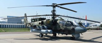
). - air (transport aircraft (
), helicopters (). - sea ().
Launchers
Rocket launchers launchers (towed launchers)
A towed launcher is a type of weapon that includes a modified combat travel (chassis) of a trailer or cannon (carriage) and the structural elements necessary for deployment, guidance and firing; essentially, like combat vehicles, it consists of a chassis and an artillery unit.
Transportation of launchers is carried out either by towing by ground transport (trucks (
), pickup trucks (), railway platforms), animals, and for short distances, calculation numbers (
,
), or by air (transport planes, helicopters) and sea modes of transport.
In the 19th century, such installations were called machines, descents, rocket field carts, rocket carts. The main structural elements were: a carriage with wheels, a mooring foot, a manual gear or screw mechanism for vertical guidance, a package of guides, a staple (fire chain) (,,
). There was a version of the machine that, according to modern terminology, combined a rocket launcher and a transport vehicle (). Towing of launch vehicles of this type was carried out by horse teams ().
The main structural elements of the RPU-14 Rocket Launcher (USSR) launcher are described below.
designed for connecting pipes into a single package and for assembling contact devices that ensure the firing of a shot.
The cradle is a welded structure consisting of sheets and pipes, with sixteen nests (holes) for the trunks.
On the back sheet of the cradle, contact devices are mounted that keep the pipes from longitudinal displacement and from rotation, ensuring the fixation of projectiles during loading and on the move, as well as the supply of electric current to the spark plugs of the projectiles to ignite the charge when firing a shot.
Pipes (barrels) are designed to direct the flight of projectiles. The pipes are located parallel to each other and fixed in the cradle in four rows, four pipes in each row.
The cradle with contact devices and sixteen pipes (trunks) is .
designed to rotate the cradle with barrels in a horizontal plane around the vertical axles of the lower machine. A cradle is mounted on the upper machine in the pins; The lifting and rotating mechanisms are fixed on the left wall of the upper machine, and the clutch bracket is fixed on the front wall.
sector type, provides the swinging part with vertical aiming angles.
screw type, provides horizontal aiming angles in a given angle range.
The lower suspension machine is a hollow steel casting within which the torsion bar suspension and leveling mechanism are assembled. The lower machine is the base of the rotating part of the launcher.
The beds (right and left) are tubular type, with constant coulters; The frame is hingedly attached to the lower machine.
Combat movement and suspension: wheels from a GAZ-AA truck with a GK tire and a hub from a D-44 cannon. The torsion bar suspension is turned on and off automatically when the beds are brought in and out.
Sights are designed to aim the rotating part of the launcher at the target.
Electrical equipment serves to ignite the powder charge of the rocket part of the projectile.
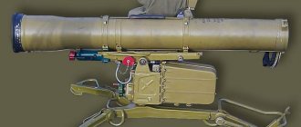
Man-portable launchers
As a rule, the design of portable launchers consists of a tripod, guidance drives, a guide or guides and a basket of sighting devices. Homemade versions with wooden or metal bipeds are also known.
The tripod serves as the basis for ensuring the stability of the launcher and mounting the guidance drives, guide (or guides) and basket of sighting devices. Structural elements mounted on a tripod machine constitute the rotating part of the launcher. The tripod machine consists of three folding supports, fixed in the combat position by means of stoppers and a base on which the rotating part is mounted.
The biped serves as the front support for a series of portable launchers. Four design solutions have been established for installations of this type:
- a biped attached to the bottom of a launch container containing an unguided missile.
- a wooden biped, on which an unguided rocket is placed (a homemade version with a biped formed by the crosshairs of two wooden sticks and tree branches).
- a metal biped on which an unguided missile is applied (homemade version (
). - biped, tubular guide, rear base plate, sight basket.
Stationary launchers
Underground launchers
Underground launchers are launchers located underground in basements or pits. Due to limited information in their design, only the following structural elements can be distinguished: the base, the guide package, presumably, and the lifting mechanism. In the combat position, the guides extend beyond the upper level of the basement or pit.
Underground-ground launchers
There are two known variants of underground-ground launchers. One of them was deployed in the Gaza Strip (,,
,), and the other (in several copies) in Iraq (,,
).
Due to limited information in the design of the first sample, the following structural elements can be distinguished: base, vertical guidance mechanism, guide package. Most likely, loading is done from the muzzle side.
In the stowed position, the installation is located underground (or partially underground) in an underground space (room) specially created for this purpose, closed (or partially covered) with doors. In the combat position, the guide package is located slightly above ground level.
In the design of the second option, the following structural elements can be distinguished: a box with a base for attaching the cradle, a cradle, a vertical guidance mechanism, and a package of guides. Most likely, loading is done from the muzzle side.
In the stowed position, the installation is located underground in a box specially created for this purpose, presumably covered with available material (a piece of metal, plywood, etc.) and covered with soil.
Railway launchers
Railway launchers were used in the USSR during the Great Patriotic War and during the war in Yugoslavia in the 90s of the twentieth century.
Domestic railway launchers structurally consisted of modified propelling parts (artillery parts) of installations (combat vehicles).
The design of the Yugoslav railway launcher used an aircraft gun block as a guide package.
The installation of the launchers was carried out on armored railway platforms as part of armored trains.
Stationary-mobile launchers
Stationary-mobile launchers are structurally composed of:
- bases (pedestals) (including the option with a built-in lower part of the turning part).
- guidance drives (mechanisms).
- farms.
- package of guides.
- console (for mounting a sight).
Stationary-mobile installations can be installed both on the surface of the earth and in the body of a car.
To be continued.
Date of first publication of the article: December 29, 2014
Last modified date: 05/21/2020
Some of the article’s materials were published in the following publications:
- Gurov S.V. Some aspects of the development of MLRS // News of Tula State University. Series Technical Sciences. Problems of special mechanical engineering. Issue 3 (Special Issue No. 12). Tula: Tula State University Publishing House, 2011. – pp. 47-50.
- Gurov S.V. From the history of the development of technical solutions for the components of rocket artillery systems in Russia // Ammunition and special chemistry. Scientific and technical journal. Issue No. 2, 2013 – Moscow. – pp. 145-153.
- Gurov S.V. Classification of ammunition and launching devices for rocket artillery // Institute of History of Natural Science and Technology named after. S. I. Vavilova. Annual scientific conference (2015). T. 2: History of natural science and technology. M.: LENAND, 2015. – P. 430,432-434.
- Gurov S.V. Historical and technical stages of improving rocket artillery in Russia // News of Tula State University. Technical science. Vol. 3. Tula: Tula State University Publishing House, 2016 – pp. 59-69.
- Gurov S.V. Design features of combat vehicles of domestic rocket artillery // Ammunition and special chemistry. Scientific and technical journal. Special issue of JSC NPO SPLAV, 2016. – Moscow. – pp. 142-148.
Types[edit]
From the shoulder[edit]
Main article: Backpack rocket
The rocket launcher category includes shoulder-launched weapons, any weapon that fires a rocket projectile at a target but is small enough for one person to carry and fire while holding it on the shoulder. Depending on the country or region, people may use the terms "bazooka" or "RPG" as generic terms for such weapons, which are actually specific types of rocket launchers. The bazooka was an American anti-tank weapon that was in service from 1942 to 1957, and the RPG (most commonly the RPG-7) was a Soviet anti-tank weapon.
A smaller variant is the gyrodrive, a small arms rocket launcher with slightly larger ammunition capacity than a .45 caliber pistol.
Recoilless rifles are sometimes confused with rocket launchers. A recoilless rifle launches its projectile using a powder charge rather than a rocket motor, although some such systems have sustaining rocker arms.
Rocket capsule[edit]
Su-20 aircraft with UB-32 missile pods, each carrying thirty-two S-5 missiles.
A missile pod is a launcher that contains multiple unguided missiles held in individual tubes, intended for use by attack aircraft or attack helicopters for close air support. In many cases, rocket pods are streamlined to reduce aerodynamic drag. The first capsules were developed just after World War II as an improvement over the previous design of launching rockets from rails, racks or tubes mounted under the wings of aircraft. Early examples of rockets launched from capsules were the American folding fin aerial rocket and the French SNEB. [8]
Large scale[edit]
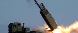
Larger scale devices that serve to launch missiles include the multiple launch rocket system, a type of unguided rocket artillery system.
How does a ballistic missile launcher work?
From the 60s to the 80s, there were 18 Titans in combat readiness around Tucson. Their launch silos were controlled from two underground bunkers. The current director of the museum, Yvonne Morris, one of the world’s first commanders of strategic missile launch crews, served in one of them.
“When the alarm sounded, I only had three minutes to get to the bunker. If I was even 10 seconds late, people below began to suspect that a war had broken out on the surface,” Yvonne recalls. From 1980 to 1984, she commanded two launch crew members and an intercontinental ballistic missile with a warhead capable of wiping out a major city.
The missile positions are well camouflaged. A half mile south of the main highway and you find yourself in the desert with rattlesnake warnings stuck in the sand. In addition to them, several low metal structures, a pair of antennas and a staircase leading underground are scattered across the hot plain. “After going down the first flight of stairs, I called down and the first door was opened for me. I went down another flight of stairs and called again, giving the password for that day,” Morris said. The crew inside looked at the monitor of the tracking system to make sure that it was really their commander, and there was no villain nearby holding a gun to his head.
If everything was in order, an electric lock on the 2.7-ton steel door would open. It is hung so skillfully that you can open it with your finger. Behind it begins a protected missile silo, mounted on giant shock absorbers, and the ceiling lights hang on springs to survive a nuclear strike. A tunnel reminiscent of the inside of a submarine with cables along the walls leads to a small round room, the launch control center. Along the walls there are racks with equipment, displays of vintage computers, intercoms. In the center there is a control panel with light displays and a chair that moves along rails embedded in the floor.
— There was only one chair, although two people were on duty at the control panel at the same time. This caused some inconvenience, but it did not lead to conflicts,” Yvonne smiles. Behind the operator's left shoulder is a red safe where confirmation codes were stored. Having received the order to launch from the command, the crew had to open the safe and make sure that the codes matched. The World War III passwords were kept behind two combination locks. The crew commander knew one combination of four numbers, and his assistant knew the other. The locks were supposed to be opened at the same time.
On the floor above there is a household compartment: a bathroom, a kitchen and a recreation area with beds. This is the only place where American missilemen could be alone. At the control center they were supposed to be in sight of each other for support. This led to funny situations. “When turning in a shift, we were supposed to vacuum the orange carpet on the floor of the control center. The vacuum cleaner is located behind the chair, it has been preserved. So, one member of the launch crew was operating a vacuum cleaner, another was standing against the wall, the third was in the center of the room, at the control panel. And everyone was in sight of each other. It’s impossible to do otherwise, because it’s impossible to entrust control of a rocket launch to one person,” Morris said.
If the worst happened, the first thing the missilemen should have heard was the siren in the bunker. Fortunately, it didn't happen. “During my military service, I slept better because when we went on duty we received detailed instructions about the world situation. And going down into the bunker, I knew: today this day has not come yet,” Yvonne smiles. And new members of the crew were always introduced to the rocket - another corridor leads to it from the control point. Once in the launch silo, the first thing a person saw was the General Electric emblem on board the Titan and the slogan. This phrase invariably caused laughter.
Help "RG"
The LGM-25 Titan II intercontinental ballistic missile was in US service from 1963 to 1987 and was equipped with the most powerful warhead in US history - a monoblock thermonuclear yield of 9 megatons. It was intended to destroy well-fortified structures, such as the secret Soviet submarine base in Balaklava. Over the years, from 50 to 60 missiles were on duty. Preparing the Titan II for launch took 58 seconds.
Links[edit]
- ↑
Joseph Needham (1974). Science and civilization in China: military technologies. The Gunpowder Epic. Cambridge University Press. item 488. ISBN. 978-0-521-30358-3. - Jump up
↑ Needham 1974, p. 493harvnb error: no target: CITEREFNeedham1974 (help) - Jump up
↑ Needham 1974, p. 495 harvnb error: no target: CITEREFNeedham1974 (help) - Congreve, William (1814), Parts of a Rocket System by J. Whiting, London (p. 19)
- Bailey, Jonathan B. (2004), Field Artillery and Firepower, Naval Institute Press, Annapolis, ISBN 1-59114-029-3 (p.177)
- Andrews, Evan. "8 Unusual Civil War Weapons". Story . APRIL 9, 2013
- Bishop, Chris (2002), Encyclopedia of World War II Weapons, Metrobooks, ISBN 978-1586637620 (pp. 169-178)
- Vectors Website - 7.0 Unguided Rockets
| Authoritative control |
|
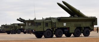
How the Soviet tactical missile system "Tochka U" was created
Back in the mid-60s, at the instigation of the USSR Ministry of Defense, work began on creating a project for a Soviet short-range operational-tactical missile capable of delivering precise strikes on enemy defenses to a depth of 100 km. For the first time, Soviet weapons relied not on the power of the warhead, but on achieving high accuracy. Previous experimental firing and work carried out in this direction clearly demonstrated the correctness of the chosen course. The military pointed out that only high-precision weapons can provide the necessary results on the battlefield. Artillery shooting at squares is a thing of the past. It was necessary to have powerful tactical fire support weapons in the front line of defense, capable of precisely hitting a specific object in the defense line of a potential enemy.
M11 Storm
The start of the project to create a new Soviet limited-range missile system was the March Decision of the Council of Ministers of the USSR in 1968. In accordance with the requirements stated in the terms of reference, the project was to be based on developments made on the basis of the M-11 “Storm” sea-based missile system. In particular, the rockets of this missile system were used for the work. Initially, the solution to the problem of creating a tactical missile system was carried out at the Fakel design bureau, which prepared the design documentation for the Yastreb complex. In the new project, the rocket control system during flight would have to rely on control from the ground. In other words, to achieve the required hit accuracy, the missile's course had to be constantly adjusted.
However, this control and guidance option did not suit the military. Soviet designers needed to completely change the missile's target guidance system. These works became the reason that the new development was called “Tochka” back in 1965. The engineers left the main components and parts of the rocket unchanged, installing a simpler inertial guidance system instead of an electronic flight control unit.
Since 1968, the mechanical engineering design bureau in Kolomna (Moscow region) has been closely involved in the creation of a new missile system on the basis of existing working projects. This enterprise was the design domain of maestro S.P. Invincible, the creator of the best examples of rocket technology.
S.P. Invincible
For reference: Under the leadership of S.P. Invincible, effective weapons were created in the Soviet Union at different times. In particular, the Shmel and Malyutka anti-tank guided missiles burned hundreds of Israeli tanks during military operations in the Middle East. Soviet Strela MANPADS became for a long time one of the main air defense systems of the ground forces at the battalion and regiment level.
The Kolomna Design Bureau team was tasked with creating a missile system that would have high shooting accuracy for destroying small targets. Before the new weapon saw the light of day, Soviet designers had to go through a difficult and thorny path. In the course of subsequent work, the developers decided to abandon previous design developments, leaving the very concept of the missile system unchanged.
Point before launch
The design documentation was completely revised and supplemented with a number of technical innovations. It should be noted that the working design created by the Kolomna Design Bureau team turned out to be acceptable for development by Soviet industry. In addition, it was possible to achieve a significant reduction in the cost of the technological part of the project. Subsequent tests, which lasted for as long as 5 years, made it possible to create a weapon that was ahead of its time. In this case, a curious situation occurred. The complex was still undergoing state tests, and serial production had already been launched at the Votkinsk Mechanical Plant in 1973. Officially, the new Soviet operational-tactical missile system "Tochka" was put into service in 1976.
Present day[edit]
Soviet IRBM base filmed during the Cuban Missile Crisis. The inability of ground-based launch facilities like this to move makes them vulnerable to detection and long-term monitoring by airborne and/or space-based surveillance systems, leading some nuclear powers to place more of their weapons on more mobile platforms such as ballistic missile submarines or transport-assembly launchers.
- China has silo-based weapons but is currently concentrating its development on expanding its submarine and mobile weapons suitable for road use, especially for tunnel networks. [6]
- Iran has silo-based weapons, having built a system of underground missile silos to protect missiles from detection and (above-ground) launchers from air strike.
- Russia has silo-based weapons, but has reduced its arsenal to a few mobile and silo-based weapons with a large number of submarine-launched Delta IV ballistic missiles. The Strategic Missile Forces of the Russian Federation (RVSN RF) (RVSN) control Russia's ground-based intercontinental ballistic missiles
- The United States has many silo-based warheads in its inventory, but has reduced its number to about 1,800 and moved most of its missiles to nuclear submarines and focused on more advanced conventional weapons.
Decommissioned missile silos[edit]
The increasing number of decommissioned missile silos has prompted governments to sell some of them to private parties. Some buyers turn them into unique homes, ultimate safe rooms, or use them for other purposes.
In 2000, William Leonard Pickard and his partner were convicted in the largest lysergic acid diethylamide (LSD) manufacturing case in history, conspiring to produce large quantities of LSD at the decommissioned SM-65 Atlas missile silo (548-7) near Wamego. Kansas. [7]