Kalashnikov PKM machine gun – video
Influenced by the experience of the Second World War, in which the Wehrmacht successfully used single machine guns MG 34 and MG 42, already in 1946 (when the RP-46 machine gun was adopted) the GAU approved the tactical and technical requirements for a single machine gun to replace the Maxim and heavy machine guns. SG-43. In the USSR, the idea of a single machine gun suitable for installation on bipods and field machines was proposed by small arms designer Vladimir Fedorov in the early 1920s.
In this regard, active design of a new class of machine gun chambered for the 7.62x54 mm R rifle cartridge for the Soviet army began. The earliest projects were Georgy Garanin's machine gun from 1947 and Vasily Degtyarev's machine gun from the same year. The first option was rejected, and there was no one to finalize the second due to the death of the creator.
At the end of the 1950s, Izhevsk designers led by Mikhail Kalashnikov became involved in the process. In addition to him, the developers of the future machine gun included V.V. Krupin, V.N. Pushchin, A.D. Kryakushin and others. They took as a basis the proven design of the Kalashnikov assault rifle, which was distinguished by its reliability and simplicity.
Kalashnikov PK machine guns
The Kalashnikov machine gun (factory index E-2) was the latest project among competitors; only in 1959 did it undergo evaluation tests, unlike, for example, its main competitor - the Tula machine gun designed by Nikitin and Sokolov, which already had working prototypes in 1956. This forced the team of workers and designers to work in emergency mode, making up for lost time. The final competitive tests of 1960 revealed advantages over the Nikitin-Sokolov machine gun:
– use of standard SGM/Maxim/RP-46 tape; – less sensitive to the gap between the piston and the gas tube; – much less sensitive to soaking, which is critically necessary for use on armored vehicles, which must necessarily cross water barriers; – there is an adjustment of the locking unit, which facilitates the interchangeability of barrels; – incomparably easier in incomplete disassembly; – less carbon pollution and easier cleaning of the pipe; – more durable parts; – 300 grams less body weight.
On October 20, 1961, by resolution of the Council of Ministers of the USSR No. 953-405, the Kalashnikov machine gun was adopted by the army. PK and PKS (GRAU index: 6P6 and 6P3) were adopted into service by order of the Ministry of Defense No. 0287 on December 28, 1961, and PKT (GRAU index - 6P7) by order of the Ministry of Defense No. 269 on December 2, 1962.
The production of machine guns was carried out at the Kovrov Mechanical Plant.
And in 1969, a modernized PC appeared on a machine designed by Stepanov. The machine gun's weight was reduced from 9 to 7.5 kg, production and ease of use were simplified. Stepanov’s machine gun is 3.2 kg lighter than Samozhenkov’s machine, the ratio of the weight of the machine to the weight of the machine gun itself has decreased from 0.86 to 0.6, and the weight of the machine gun on the machine (without belt) is up to 12.0 kg, but the accuracy of fire is not the same worsened. Accordingly, new versions of the machine gun were designated PKM, PKMS, PKTM and PKMB. In the new competition, the PKM’s main competitor was again a machine gun designed by Nikitin, but with a different design.
Options and modifications
PC - Kalashnikov machine gun with bipod.
The PKB and PKS variants differ from the PC only in the factory configuration that determines their purpose:
– if the PC is installed on a tripod machine, it is called PKS (machine machine). – if the PC is installed on an armored personnel carrier (using a rotating bracket), then it is called PKB (armored personnel carrier). The swivel bracket is officially called the “Installation”. The machine gun was installed only on armored personnel carriers that do not have a turret (armored personnel carriers with a turret use the PKT).
The tripod machine for the PKS and the installation for the PKB had a serial number and were assigned in the unit to a specific machine gun by an entry in the form. All three machine guns (more precisely, one with three names, depending on where it is installed) were put into service in 1961 to replace the RP-46, SGM and SGMB, respectively.
A tripod machine for PKS facilitates targeted shooting of a machine gun from a bunker or trench, shooting at air targets and shooting in mountainous areas.
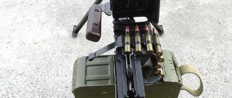
The installation for the PCB consists of a swivel (providing horizontal aiming), a sector (providing vertical aiming), a holder (holding a high-capacity cartridge box for 200/250 rounds), a spring shock absorber softening recoil, a frame (connecting the machine gun with the installation) and a cartridge case catcher (allowing to avoid cluttering the internal space of the armored personnel carrier). The design of the PCB included a non-removable bipod and butt as on a regular PC, which made it possible, if necessary, to use it outside the combat vehicle.
The PKB was used on armored personnel carriers that had an open-top design without a rotating turret (BTR-40, BTR-152, BRDM-1, BTR-50) as well as on the turretless early versions of the BTR-60 - BTR-60P and BTR-60PA. Since these types of armored personnel carriers were almost completely removed from service with the USSR Armed Forces, this modification is rare.
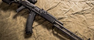
PKM is a modernized Kalashnikov machine gun. Adopted into service in 1969 to replace the PC. Differs in less weight.
PKMS and PKMB respectively .
At the same time, a new 6T5 tripod machine designed by Stepanov was adopted for use in the PKMS version. While maintaining all the positive qualities of the previous machine, it is 3 kg lighter, and in addition it has: - special belts for fastening boxes with tapes in the stowed position; thus, in the stowed position, up to 2 boxes with belts of 200 rounds of ammunition are carried along with the machine; — mounting on the legs of the machine for a box with tape in the firing position; thus, in battle, one soldier can carry a machine gun along with the machine and the cartridge box without removing the belt from the machine gun. In addition, just like in the Samozhenkov machine, the new machine can be equipped with a machine gun for anti-aircraft shooting.
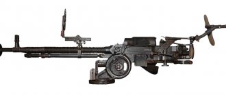
PKT is a Kalashnikov tank machine gun, with a heavier barrel and equipped with an electric trigger. It is installed in the turrets of tanks and other armored combat vehicles (BMP, BMD, BTR-60PB/70/80/90, MT-LB, BMPT, BRDM-2, BRM-1K). Adopted into service in 1962 to replace the SGMT machine gun.
Kalashnikov PKM machine guns
PKTM is a modernized Kalashnikov tank machine gun. Adopted into service in 1998.
AEK-999 “Badger” - PKM with a new machine-gun barrel produced by the Kovrov Mechanical Plant. The biggest change in the weapon's design compared to the single PKM machine gun is the new non-replaceable barrel, which uses aircraft-grade materials. It is equipped with a removable low-noise firing device, which allows to significantly reduce the acoustic load on the members of the machine gun crew and reduce visibility by reducing noise and eliminating the muzzle flash. There is evidence that the sound of a shot, depending on the type and terrain, is no longer audible at a distance of 400-600 m. A heat dissipator is located above the machine gun barrel, which reduces the distorting effect of warm air on the aiming line and makes the barrel structure rigid. Barrel life is 33-40 thousand shots.
Pecheneg - PKM with a barrel of forced cooling due to the energy of powder gases. Developed at TsNIITochmash.
Type 80 - Chinese PKM. The machine gun entered service with the PLA in the 1980s in 1983. At first it was assumed that the Type 80 would replace the Type 67, previously developed in the PRC, which had proven itself well at the military district training ground in Chengdu. However, then the development was curtailed, and only the Type 67 remained in service. Several Type 80 samples were tested in the Chinese Navy, then they were modernized, and the ground forces received a modification of the Type 86, which was put into service with the PLA.
Zastava M84 - Serbian PKM. One of the differences is the stock is made of solid wood.
Design
The Kalashnikov machine gun uses gas-operated automatics; the barrel is locked using a rotating bolt. Fire is fired only in bursts, from an open bolt. In the infantry and armored personnel carrier versions, the machine gun is equipped with a folding bipod, a skeleton stock and a pistol grip fire control. In the easel version, the machine gun is mounted on a universal folding tripod machine. To fire at air targets, the machine has a special adapter rod. The sights are open and adjustable. The machine gun can also be equipped with optical or night sights. PKM of the Hungarian army
The trigger mechanism with a return spring provides only automatic fire. The gas outlet unit has a three-position gas regulator. The barrel is air-cooled, the barrel is quick-changeable and has a carrying handle for easy replacement. The cartridges are fed from a non-scattered metal tape, the tape is fed only from the right.
Incomplete disassembly of the PKM machine gun
The cartridge feed from the belt is two-stage; when the bolt group moves back, the cartridge is pulled out of the belt by the extractor grips and lowered to the feed line. Then, after pressing the trigger, the bolt group moves forward, the cartridge is sent into the barrel. The combat cock is located on the bolt frame, and the firing pin is connected to it. When, after locking the bolt, the bolt frame continues to move forward, the firing pin, under its action, moves along the channel in the bolt frame and breaks the primer. In the tank version of the machine gun (PKT), instead of a trigger, an electromagnetic trigger mechanism (electric trigger) is installed, activated by a button located on the gun pointing unit on a tank or infantry fighting vehicle or located on the turret rotation handle on an armored personnel carrier. The electric trigger is connected to the on-board network of the armored vehicle with a cable protected by a flexible tube made of twisted wire 50 centimeters long. In case of failure of the electric trigger or lack of voltage in the on-board network of the armored vehicle, the tank version of the machine gun (PKT) is equipped with a mechanical firing system. The mechanical trigger is located above the electric trigger block on the butt plate of the receiver and is represented by a horizontal trigger held by a vertical safety bar. Machine guns of the PK / PKM series are distinguished by exceptionally high reliability and enjoy deserved popularity among the troops.
PKT tank machine gun
The tank version has a heavier and longer barrel, as well as a modified gas exhaust unit to reduce gas contamination in the fighting compartment. A heavy barrel with thicker walls allows for more intense fire without replacing the barrel. The tank version lacks mechanical sights, a stock, a pistol grip and a bipod. To open fire, an electric trigger is used, connected to the on-board network.
If there is no voltage in the on-board network, in the back of the PKT receiver, above the electric trigger block, there is a mechanical trigger, made in the form of a vertical trigger, held by a spring-loaded fuse located in the horizontal plane. The fuse fits into the slots of the trigger with its protrusions, thereby securing it. In this case, to fire, you need to press the safety down and press the trigger in the direction of the shot. At the end of firing, the trigger and safety lever return to their original position under the influence of springs when the safety locks the trigger.
The only standard specialized device for PKT is the so-called Cold Sighting Tube (TCP), which serves to align the tank machine gun and sight, and is individually attached to each machine gun.
Conversion of the PKT machine gun into an infantry version
During numerous local conflicts in the early 90s, in the territory of the former USSR, representatives of illegal armed groups developed an acute demand for light machine guns as the main means of supporting infantry. At the same time, the warring parties acquired a large number of PKT machine guns, stolen from military units, taken from armored vehicles damaged in battles or disabled. A natural step to overcome such a shortage should be considered small-scale production of converting PKT tank machine guns into an infantry version in civilian mechanical workshops.
The conversion scheme that became most widespread was as follows: — The electric trigger unit was removed from the machine gun. — To the vacant space on the butt plate of the receiver, a butt with a pistol grip made of a single piece of plastic or repeatedly glued layers of plywood was attached with a riveted connection using steel plates on the sides of the receiver. — The safety bar was removed, and the partially cut trigger was connected to a homemade hook, under which a slot was cut in the bottom of the receiver. — On the barrel gas outlet assembly, a tin bracket with a bipod made of a thick steel rod with pointed ends was bolted. — A protrusion with a front sight was attached to the barrel in the front part by welding. — A steel corner with a radial cutout, which played the role of a sighting bar, was attached to the receiver cover with a riveted connection.
Due to the maximum simplification of the conversion process, the resulting machine guns did not have such elements of the PKM infantry machine gun as: a fire safety device, a bracket for attaching a box of cartridges, a safety guard on the trigger, a holder on the bipod for a prefabricated ramrod, sockets in the butt for an oil can and for a pencil case with cleaning supplies. Due to such simplifications, the converted PKT machine gun was inferior to the PKM in terms of size and weight, ease of carrying in combat, safety and accuracy of aimed fire. The only advantage of the converted PKT over the PKM was the ability to conduct more intense and prolonged fire thanks to the weighted barrel. Machine guns of a similar design were widely used during the Karabakh War, during the First and Second Chechen Wars, in the Civil War in Tajikistan, in the South Ossetian War (1991-1992), in the Georgian-Abkhaz War (1992-1993).
During the military operations in Donbass, converted PKTs were used by militias from Gorlovka and Ukrainian troops.
Production
Azerbaijan: two versions of the PKM are produced (chambered 7.62x54 mm R): the general-purpose UP-7.62 (weight 7.5 kg) and the special HP-7.62 (weight 7 kg).
Bangladesh: Produced by Bangladesh Ordnance Factories under the symbol BD-14.
Bulgaria: in 1971-1973, serial production of the PK machine gun was mastered and started, and in 1976-1978 - of the PKT tank machine gun, now PKM is produced; subsequently, modified versions of the PKM machine gun chambered for 7.62x51 mm NATO cartridge were developed;
Iran: Produced by Defense Industries Organization;
PRC: PKT is produced under the name Type 59T; The PKM is produced under the name Type 80. The export version chambered for 7.62 NATO cartridge is produced under the designation CF06 or CS/LM4;
DPRK: produced under the name Type 73 in a version with combined power supply: 30-round magazine or cartridge strip.
Poland: PKM, PKT machine guns and their modifications have been produced since 1968; after the transition to NATO standards in 1997-2000, the Tarnow Mechanical Plant developed the UKM-2000 variant chambered for 7.62x51 mm.
Russia: PKM, PKTM, PKMS, PKMB are produced;
Romania: the PKM machine gun is produced by the Romarm company (a division of the Kujira Arms Factory) under the name Mitraliera md. 66 and PKT under the name MMB;
Serbia: the PK machine gun is produced under the name Zastava M84, PKT - under the name Zastava M86;
Sudan: Manufactured by Military Industry Corporation under the name Mokhtar;
Ukraine: PKM (under the name KM-7.62) and PKT (under the name KT-7.62) are produced
Chapter II DISASSEMBLY AND ASSEMBLY OF A MACHINE GUN
Chapter II
DISASSEMBLY AND ASSEMBLY OF A MACHINE GUN
5. Disassembly of a machine gun can be incomplete or complete: incomplete - for cleaning, lubricating and inspecting the machine gun; full - for cleaning when the machine gun is heavily soiled, after being in the rain or snow, when switching to a new lubricant and during repairs. Excessively frequent disassembly of a machine gun is harmful, as it accelerates the wear of parts and mechanisms.
Disassemble and reassemble the machine gun on a table or clean mat; Place parts and mechanisms in the order of disassembly, handle them carefully, do not place one part on top of another and do not use excessive force or sharp blows. When assembling a machine gun, compare the numbers on its parts: for each machine gun, the number on the receiver must correspond to the numbers on the gas tube, bolt frame, bolt, receiver cover and other parts of the machine gun.
Training in disassembly and assembly on combat machine guns is allowed only in exceptional cases and with special care in handling parts and mechanisms,
6. The procedure for incomplete disassembly of the machine gun:
1) Install the machine gun on the bipod. Holding the machine gun by the fore-end in a vertical position with your left hand, release the legs of the bipod from the spring fastener with your right hand, move the bipod away from the barrel so that its legs take a fixed position; place the machine gun on the bipod with the muzzle to the left.
2) Separate the store. Holding the machine gun with your left hand by the neck of the butt, grab the magazine with your right hand (Fig. 3); Pressing the latch with your thumb, push the bottom of the magazine forward and separate it. After this, check to see if there is a cartridge in the chamber , to do this, lower the translator down, move the bolt handle back, inspect the chamber, release the bolt handle and release the hammer.
Rice. 3.
Store branch
3) Take out the pencil case with the accessory. Press the cover of the butt socket with the finger of your right hand so that the pencil case comes out of the socket under the action of a spring; Open the pencil case and take out the cleaning cloth, brush, screwdriver, drift and pin.
4) Separate the cleaning rod. With your left hand, pull the end of the cleaning rod away from the barrel so that its head comes out from under the stop of the front sight base (Fig. 4), and pull the cleaning rod forward. When separating the ramrod, it is allowed to use a drift.
Rice. 4.
Cleaning rod compartment
5) Separate the receiver cover. With your left hand, grab the neck of the butt, with the thumb of this hand, press the protrusion of the guide tube of the return mechanism, with your right hand, lift up the back of the receiver cover (Fig. 5) and separate the cover.
6) Separate the return mechanism. Holding the machine gun with your left hand by the neck of the butt, with your right hand push forward the guide tube of the return mechanism until its heel comes out of the longitudinal groove of the receiver; lift the rear end of the guide tube (Fig. 6) and remove the return mechanism from the bolt frame channel.
Rice. 5.
Receiver cover compartment
Rice. 6.
Return mechanism compartment
7) Separate the bolt carrier with the bolt. Continuing to hold the machine gun with your left hand, with your right hand, pull the bolt frame back as far as it will go, lift it along with the bolt (Fig. 7) and separate it from the receiver.
Rice. 7.
Bolt carrier compartment with bolt
 Separate the bolt from the bolt frame. Take the bolt frame in your left hand with the bolt up (Fig. 8); With your right hand, pull the bolt back, turn it so that the leading lug of the bolt comes out of the figured cutout of the bolt frame, and move the bolt forward.
9) Separate the gas tube from the barrel lining. Holding the machine gun with your left hand, with your right hand put the accessory case with a rectangular hole onto the protrusion of the gas tube contactor, turn the contactor away from you to a vertical position (Fig. 9) and remove the gas tube from the gas chamber pipe.
Rice. 8.
Separating the bolt from the bolt frame
Rice. 9.
Rotating the gas pipe closure using the accessory case
7. The procedure for assembling the machine gun after partial disassembly:
1) Attach the gas tube to the barrel lining. Holding the machine gun with your left hand, with your right hand push the gas tube with its front end onto the gas chamber pipe and press the rear end of the barrel lining to the barrel; Using the accessory case, turn the contactor toward you until its lock enters the recess on the sight block.
2) Attach the bolt to the bolt carrier. Take the bolt frame in your left hand, and the bolt in your right hand and insert the bolt with the cylindrical part into the channel of the bolt frame; turn the bolt so that its leading protrusion fits into the figured cutout of the bolt frame, and push the bolt forward.
3) Attach the bolt carrier with the bolt to the receiver. Take the bolt carrier in your right hand so that the bolt is held in the forward position with your thumb. With your left hand, grab the neck of the butt, with your right hand, insert the gas piston into the cavity of the sight block and push the bolt frame forward so that the bends of the receiver fit into the grooves of the bolt frame, press it with a slight force to the receiver and push it forward.
4) Attach the return mechanism. With your right hand, insert the return mechanism into the bolt frame channel; compressing the return spring, move the guide tube forward and, lowering it slightly downwards, insert its heel into the longitudinal groove of the receiver.
5) Attach the receiver cover. Insert the front end of the receiver cover into the semicircular cutout on the sight block; press the rear end of the cover with the palm of your right hand forward and downward so that the protrusion of the guide tube of the return mechanism fits into the hole in the receiver cover.
6) Release the trigger and put the safety on. Pull the trigger and raise the translator up to full stop.
7) Attach the cleaning rod.
Insert the pencil case into the butt socket. Place the accessory in the pencil case and close it with the lid, place the pencil case bottom into the butt socket (Fig. 10) and push it down so that the socket is closed with the lid.
Rice. 10.
Inserting a pencil case into the stock socket
9) Attach the magazine to the machine gun. Holding the machine gun by the neck of the butt with your left hand, insert the magazine hook into the receiver window with your right hand (Fig. 11) and turn the magazine towards you so that the latch jumps over the supporting ledge of the magazine cover.
Rice. eleven.
Joining a store
10) Fold the legs of the bipod. Place the machine gun with your left hand in a vertical position; with your right hand, slightly bringing the legs of the bipod together (Fig. 12), press them to the trunk and secure them with a spring fastener.
8. The procedure for completely disassembling the machine gun:
1) Carry out partial disassembly , guided by Art. 6.
2) Disassemble the store:
a) Drum
:
— separate the magazine cover : place the magazine with the bottom of the case on the table; Using a drift, press the stopper of the cover nut with your right hand; turn the nut with your left hand? turn and remove it upward from the feeder axis; resting your thumbs on the neck of the magazine, grab the lid with the rest of your fingers (Fig. 13) and remove it;
Rice. 12.
Bipod leg folding
Rice. 13.
Magazine lid compartment
— separate the feeder : take the magazine with your left hand so that the thumb rests on one of the shaped protrusions of the feeder, and the rest clasps the neck of the magazine; With the thumb of your left hand, turn the feeder slightly clockwise, and remove the rammer from the neck with your right hand (Fig. 14); holding the magazine body with your left hand, with your right hand, smoothly turning the feeder counterclockwise, release the spring and remove the feeder from the axis;
Rice. 14.
Rammer Section
— separate the feeder spring : take the feeder in your left hand with the spring pin upward, and with your right hand, using a drift, remove the end of the spring from the pin; pull the spring out a little, then use the accessory pencil to separate the spring from the feeder (Fig. 15);
Rice. 15.
Feeder spring compartment
— separate the loading lever : place the magazine on the table with the loading lever up, press the stopper with a drift; turn the nut with your left hand? turn and lift it up; holding the magazine body with your left hand, lift the loading lever with your right hand (Fig. 16) and, smoothly lowering the spring, separate it from the body; remove the stoppers with the spring from the feeder axis hole.
b) Box-shaped
. Take the magazine in your left hand with the lid up, the convex part away from you; with your right hand, using a drift, press the protrusion of the locking bar into the hole on the magazine cover with the thumb of your left hand, move the cover slightly forward (Fig. 17), remove the cover from the body with your right hand, while holding the locking bar with the thumb of your left hand; gradually releasing the spring, remove it together with the locking bar and the feeder from the magazine body; separate the feeder from the spring.
Rice. 16.
Loading lever compartment
Rice. 17.
Box magazine lid compartment
Rice. 18.
Return clutch compartment
3) Disassemble the return mechanism. Take the return mechanism in your left hand, place the guide tube vertically (heel down) on the table (stop), compress the return spring down and remove the coupling with your right hand (Fig. 18); remove the spring from the guide tube; separate the guide rod from the tube.
Rice. 19.
Pushing out the pin when separating the ejector and firing pin from the bolt
4) Disassemble the shutter. Use a punch to push out the pin holding the firing pin and the ejector axis (Fig. 19), and remove the firing pin from the bolt channel; push out the ejector axis with a drift and remove the ejector with the spring from the bolt.
5) Disassemble the trigger mechanism (disassembly is carried out under the guidance of an officer or gunsmith):
— separate the single-fire sear, hammer retarder and trigger : holding the machine gun with your left hand by the receiver, use your right hand to press the self-timer lever with a drift and disconnect the self-timer sear from the trigger; pull the trigger; use the thin end of a drift to lift the left end of the mainspring and use your fingers to place it behind the cocking mechanism; use a screwdriver to remove the long end of the self-timer spring from the annular groove of the trigger axis; Using a drift, move the trigger axis to the left and remove it; gradually removing the drift, with the fingers of your left hand, remove the single fire sear, its spring, the retarder spring and the trigger retarder from the receiver; use a hammer to lift up the right end of the mainspring and place it behind the cocking mechanism with your fingers (Fig. 20); pressing the index finger of your left hand from below on the tail of the trigger, lift the trigger upward and remove it from the receiver with your right hand (Fig. 21);
Rice. 20.
Inserting the right end of the mainspring behind the cocking protrusion
Rice. 21.
Removing the trigger from the receiver
— separate the trigger : by pressing the long end of the self-timer spring with a screwdriver, remove it from the annular groove of the trigger axis and use a drift to move the trigger axis to the left; holding the trigger with your right hand, remove the trigger axis with your left hand; turn the trigger so that the left trunnion is directed towards the chamber, and remove the trigger from the receiver (Fig. 22); separate the mainspring from the trigger;
— separate the self-timer : use a drift to move the self-timer axis to the left and remove it; remove the self-timer with the spring through the magazine window (Fig. 23); separate the spring from the self-timer;
— separate the translator : turn the translator up to a vertical position, move it to the right and separate it from the receiver.
Rice. 22.
Removing the trigger from the receiver
Rice. 23.
Removing the self-timer with a spring from the receiver
6) Separate the forend (the forend is separated in rare cases: when removing warehouse grease, after the machine gun gets into water, etc.). Take the machine gun with your left hand by the fore-end, with your right hand, using a screwdriver or accessory case, turn the fore-end lock half a turn forward; with the thumbs of both hands, move the coupling (Fig. 24) from the forend to the gas chamber; move the forend forward and separate it from the barrel.
Rice. 24.
Shifting the coupling
9. The procedure for assembling the machine gun after complete disassembly:
1) Attach the handguard. Holding the machine gun with your left hand by the receiver, with your right hand, attach the fore-end from below to the barrel and slide it towards the receiver so that the protrusion of the fore-end fits into the socket of the receiver; push the coupling onto the forend and turn the lock half a turn back.
2) Assemble the trigger mechanism (to avoid mixing up the parts of the firing mechanism of several machine guns, before assembling, you must check the numbers on the single-fire sear, trigger retarder, trigger, hammer and self-timer):
— attach the translator : holding the machine gun with your left hand, with your right hand insert the translator sector into the shaped hole in the right wall of the receiver so that the trunnions fit into the holes in the walls of the receiver; put the translator on automatic fire (AB);
— attach the self-timer : insert the short end of the spring into the hole in the self-timer protrusion and insert the self-timer with the spring into the receiver through the magazine window; put the self-timer lever in its place and insert a drift on the right into the holes for the self-timer axis and spring; holding the self-timer with the spring with your right hand, insert the axis with your left hand (Fig. 25);
Rice. 25.
Inserting a self-timer axis
— attach the trigger : put the mainspring on the trigger pins with a loop from the cocking side (Fig. 26) and place its ends behind the cocking cock; holding the trigger and the ends of the spring with the fingers of your right hand, insert the trigger into the receiver with the left pin facing the chamber; with the index finger of your left hand, press the long end of the self-timer spring to the bottom of the receiver, turn the trigger and align its hole with the corresponding holes in the receiver; insert the trigger axis on the left, pushing it to the right until it stops (a click should be heard); Using the fingers of your right hand, remove the right end of the mainspring from the cocking mechanism and lower it to the bottom of the receiver;
Rice. 26.
Mainspring position on trigger
— attach the single-fire sear and trigger retarder to the trigger : insert the spring into the hole in the single-fire sear; holding the trigger by the tail in your left hand, place the single-fire sear on it with your right hand so that the lower end of the sear spring fits into the notch of the trigger, then between the sear and the right wall of the trigger place the trigger retarder spring with the long end up and forward; Align the fingers of your right hand with the holes for the axle on the trigger, sear and retarder spring, insert a pin into them on the left side with the pointed end (it is stored in the accessory case); put the trigger retarder on the pin on the right side and push it to the right until it stops; using a drift, insert the long end of the spring into the groove of the trigger retarder latch;
— attach the trigger : put the trigger in its place in the receiver; use a hammer to lift the right end of the mainspring upward and place it on the rectangular protrusion of the trigger; insert the trigger axis with your left hand, gradually pushing the pin to the right side; the long end of the self-timer spring should be on top of the axis; use a drift to insert the long end of the self-timer spring into the annular groove of the trigger axis; With the fingers of your right hand, remove the left end of the mainspring from the cocking mechanism and place it on the rectangular protrusion of the trigger.
By pressing a drift on the ends of the self-timer axes, hammer and trigger, check that the axes are locked with the long end of the self-timer spring; cock the self-timer.
3) Assemble the shutter. Insert the ejector with the spring into the shutter cutout; Having pressed the ejector, insert the ejector axis into the hole so that the cutout on the axis faces towards the cylindrical part of the bolt. Take the bolt with your left hand with the leading protrusion to the right, the cylindrical part towards you, and insert the firing pin into the bolt channel with the large cutout upward; From the side of the leading protrusion, insert a pin into the bolt hole.
4) Assemble the return mechanism. Insert the guide rod (notched end first) into the guide tube from the protrusion side; insert the cleaning rod with the head forward into the guide tube and, placing the cleaning rod with the guide tube and rod vertically on the table (stop), put the spring on the guide rod and tube; compress the spring so much that the end of the guide rod comes out of it; place the coupling on the end of the guide rod; release the spring; remove the cleaning rod from the guide tube.
5) Assemble the store:
a) Drum
:
— attach the loading lever : insert stoppers with a spring into the hole in the feeder axis; insert the end of the spring of the loading lever into the hole in the bottom of the housing; pressing the lever to the bottom of the case, turn it counterclockwise, overcoming the resistance of the spring, until the pusher hits the window of the bottom of the case; secure the lever with a nut;
— assemble the feeder : insert the inner end of the spring into the feeder; insert the wipe into the hole in the accessory's pencil case, insert the pencil case into the hole in the front wall of the feeder so that the spring hook fits into the hole on the pencil case; turning the pencil case clockwise by rubbing (Fig. 27), insert the spring into the feeder until the outer end of the spring engages the feeder pin;
— attach the feeder : put the feeder on the axle, turn the feeder clockwise one to one and a half turns and, holding it in this position, insert the rammer into the neck and release the feeder;
— attach the magazine cover : put the cover on the feeder axle and secure it with a nut.
Rice. 27.
Attaching the spring to the feeder
b) Box-shaped
. Attach the feeder to the magazine spring by inserting the first turn of the free end of the spring under the bend of the feeder; insert the spring with the feeder into the magazine body; push the locking bar into the body and, holding it in this position, put the magazine cover on the body so that it is held by its grips on the bends of the body, and the protrusion of the locking bar slides into the hole in the cover (a click should be heard).
6) Further assembly should be carried out in accordance with Art. 7.
Photo of the PKM machine gun
Kalashnikov PKMS machine gun on a 6T5 machine designed by Stepanov
The butt plate of the PKM stock (on the right) is equipped with a folding shoulder pad, designed for more rigid fixation of the machine gun when firing
Slotted machine gun flash suppressors (from bottom to top): PK, PKM of early releases, PKM currently in production
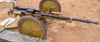
PKS machine gun (PK on a 6T2 Samozhenkov machine) with an ammunition box with a belt for 250 rounds