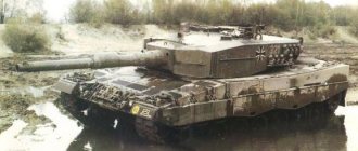
The heavy tank "Tiger" has long and firmly become a symbol of the armored forces of Nazi Germany. Despite the fact that it was far from the most popular vehicle, it is with it that most people associate the Panzerwaffe of the Third Reich.
Why did she appear?
Because soon after the invasion of the USSR, the Germans became convinced that they did not have an adequate response to the Soviet KV and T-34 tanks. They maintained parity only thanks to the “acht-acht” – 88-mm FlaK-18/36 anti-aircraft guns. Mounted for direct fire, they proved to be very effective against Soviet tanks.
A gun of this caliber was installed on the new Tiger tanks, developed and put into mass production in August 1942.
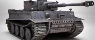
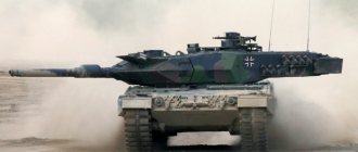
Pz.Kpfw.VI Tiger
How much does the Tiger tank, the German “predator No. 1”, weigh? The combat weight of the Pz.Kpfw.VI Tiger tank is 57 tons.
German tank T-6 "Tiger" - characteristics
The first 250 Tigers received a 12-cylinder Maybach HL 210P30 gasoline engine with a power of 650 hp. All subsequent ones are Maybach HL 230Р45 with 700 hp. For use in North Africa, air filters were additionally installed at the rear of the tanks.
The capacity of the tank's four gas tanks was 534 liters, and the rated fuel consumption was 270 liters per 100 km (when driving on the highway), 480 liters when driving off-road. In reality, this tank “ate” even more gasoline - 5-6 liters for every kilometer it traveled.
The Maybach semi-automatic gearbox provided 8 forward gears and 4 reverse gears. To switch them, you only had to move the lever, and the servo would engage the desired gear without the participation of the driver.
The tank's chassis included 24 road wheels, arranged in 4 rows on one side, in a checkerboard pattern. The torsion bar suspension provided excellent ride smoothness, which was important for good aiming while moving.
The tracks were used for combat - 725 mm wide and transport - 520 mm wide (they were used when driving on paved roads and transporting tanks by rail.
The overall dimensions of the Tiger tank are as follows: length - 6.316 m; with a cannon - 8.45 m; width – 3.705 m; height – 3 meters exactly. Travel speed – up to 38 km/h.
Internal layout
Thanks to rational design, the Tiger had a fairly large volume of the fighting compartment, which comfortably accommodated 5 crew members. Namely, the driver, gunner, loader, gunner-radio operator and commander. Everyone had their own comfortable place, equipped with everything they needed.
The standard driver's seat, equipped with a comfortable seat and a new steering wheel, had excellent visibility and excellent security. The gunner had at his disposal effective observation devices that allowed him to fire at enemy targets from a long distance. Not far from the loader there was an individual embrasure, which allowed him to observe the battlefield. The gunner-radio operator, whose main weapon was the MG-34 machine gun, had a powerful FuG-5 radio station, which made it possible to transmit information over a distance of up to 9.4 kilometers in Morse code mode and up to 6.4 kilometers in telephone mode. The crew commander was located directly above the gunner and had a periscope panorama, thanks to which he monitored the battlefield even with the hatch closed.
German tank "Tiger" - weapons
The gun of this tank - 88 mm KwK-Z6 L/56 - became a special tank version of the Flak-18/Z6 anti-aircraft gun from the Krupp concern. The gun barrel was equipped with a 2-chamber muzzle brake and an electric trigger. The length of the gun barrel was 493 cm. Its full ammunition load consisted of 92 shells.
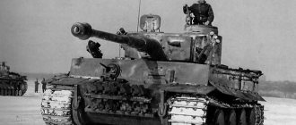
Tiger I
The Tiger tank was also armed with two MG34 machine guns installed in the hull and turret. Their ammunition consisted of 4800 rounds. The smoke grenade launchers, which were initially installed on the turret, were later replaced with grenade mortars - a means of protection against enemy infantry.
The tank's armament was equipped with telescopic sights with 2.5x magnification and a field of view of 23 degrees. The MG34 KZF2 machine gun also had a 1.8x telescopic sight. All this was excellent optics from Carl Zeiss.
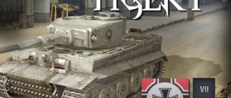
KwK 36 L/56 for Tiger I
Background
Developed in 1942 in response to the appearance of the Russian KV-1 and T-34 tanks on the Eastern Front, the Tiger I (German: Panzerkampfwagen VI) was decided to be equipped with an 88 mm cannon as its main armament.
The choice of the developers fell on the anti-aircraft 88-mm Flak 36, which served as a prototype for the creation of a tank gun.
And to understand why the anti-aircraft gun served as the basis for the creation of a tank gun, you need to go back to the times of the Spanish Civil War of 1936-39.
To help the Spanish nationalists, the German authorities sent a military contingent known as the "Condor Legion", which consisted mainly of Luftwaffe personnel and was equipped with the new 88 mm Flak 18 anti-aircraft guns (predecessor of the Flak 36). From the beginning of 1937, "Flak" artillery was used more and more in battlefields where its accuracy, rapid fire and range were most suitable. Ultimately, this led to the use of the Flak in the last great offensive of the Spanish War, in Catalonia, in the following proportions: 7% against air targets and 93% against ground targets of the total number of rounds fired from the guns. It was at this time that the Germans saw the future potential of the 88 mm gun as an anti-tank gun.
Tank gun
To install a heavy anti-aircraft gun with strong recoil in the Tiger turret, a muzzle brake was installed on the tank version of the gun, which significantly reduced the amount of recoil. Also, to improve the ballistic characteristics of the gun, the barrel length was increased from 53 calibers to 56. The horizontal sliding bolt used on anti-aircraft guns was replaced with a vertical one, and the mechanical trigger with an electric one, as was customary for all German tanks during the war.
The tank gun received the designation KwK 36 L/56 (German: Kampfwagenkanone 36). It was attached to the front of the cradle to a massive cast gun mantlet. The mask, in turn, had pins and rotated in a vertical plane along with the gun.
Structurally, the gun included: a barrel with a casing; two-chamber muzzle brake; breech with locking mechanism; cradle; hydraulic retractor and hydropneumatic retractor; crew protective frame with a tray for spent cartridges attached to it.
Trunk
The barrel had a fastening casing located in the place of the highest gas pressure (a section approximately 2.6 meters long from the breech). The casing, dressed with interference, created compressive stresses in the barrel, and itself experienced tensile stresses. As a result, the inner and outer layers of the barrel metal more evenly absorbed the stresses created by the pressure of the powder gases when fired, which made it possible to increase the maximum pressure in the barrel.
A retaining ring was installed at the end of the casing.
The overall length of the gun (from the muzzle brake to the breech) is 5316 mm. Barrel length - 56 calibers, i.e. L=88*56=4930 mm. Thanks to the increased barrel length, the projectiles received a high initial velocity, which provided them with a very flat flight path and greater armor penetration. The barrel was rifled to give rotation to the projectile and launch it along a more accurate trajectory. There were a total of 32 helical riflings, turned to the right side, with a depth of 1.5 mm, a width of 3.6 mm and a distance of 5.04 mm from each other. The length of the rifled part of the barrel is 4093 mm.
The KwK 36 L/56 turned out to be a very powerful and accurate gun. German authorities thoroughly tested the accuracy of the 8.8 cm gun. The dimensions of the target in the tests were 2.5 m wide and 2 m high. Shooting was carried out from fixed distances, for example the Pzgr 39 projectile hit the target with 100% accuracy at 1000 m, at 2000 m the accuracy decreased to 87% and to 53% at 3000 m. However, these impressive figures should be regarded as taken from a controlled “test” » environment. With variations introduced by barrel wear, quality of ammunition and human error, the accuracy percentage drops significantly at long ranges and will undoubtedly decrease in accuracy in combat conditions where there are additional factors such as terrain, atmosphere and difficult circumstances operating in combat.
There is no doubt that the cannon gave the Tiger an advantage on the battlefield. It could hit most enemy tanks, at ranges beyond which the enemy could fire back effectively.
A total of 1,514 guns were assembled and accepted by inspectors from the Army Weapons Office (German: Heereswaffenamt, abbr. HWA). The guns were produced by two main assembly companies: DHHV (short for Dortmund-Horder Huttenverein AG) and Wolf Buchau. Each barrel cost 18,000 Reichsmarks.
The guns were marked with a mark on the cut of the breech. In the lower left corner they put the year of manufacture (two digits) and the manufacturer's code. DHHV had the code "amp" and Wolf Buchau "cxp" (author's guess). In the lower right corner was the serial number of the gun, consisting of the letter R (short for German Rohr - gun) and numbers. Under the number in small print was indicated the contract number with the manufacturer, consisting directly of two letters FL (abbreviated from German Fertig Lieterant - Completed Delivery), serial number and manufacturer code.
Below is a photo of the breech of the Tiger 131. As you can see, the gun of this machine was produced in 1942 (number “42”) under contract number 79 and has the serial number R179. The stamp line "S: M: 79 FL amp" presumably indicated another contract marking.
As is known, a total of 1354 Tigers were produced, which means that only 160 “spare” barrels remained. Barrel life was estimated at 6,000 rounds and depended on the type of shells used, which wore out the barrel and made the gun slightly less accurate. For this reason, it was unlikely that most tanks would have their barrels changed during their service life.
Muzzle brake
To reduce recoil and facilitate the operation of recoil devices, the KwK 36 was equipped with a large two-chamber muzzle brake. The muzzle braking system works by trapping the expanding gases that escape the barrel after the projectile has ejected. The gases push the barrel forward from the tank and thereby counteract some of the recoil force. Tigerfibel stated that the muzzle brake fitted to the Tiger reduced recoil by 70%, and warned that the gun should not be fired if the brake had been shot off or damaged.
The muzzle brake was screwed to the end of the barrel and secured with a locking ring.
Some changes were made to the muzzle brake during production, so it is worth knowing that there were also early and late versions of it.
Balancer and locking device
A heavy muzzle brake on a long barrel shifted the center of mass of the gun towards the barrel, which led to an imbalance of the gun relative to the trunnions of the gun mantlet. To eliminate this problem, on early versions of the tank, the gun was balanced by a heavy spring located in a tube along the starboard side of the turret and attached to the gun mantlet through a system of levers.
On later versions, the balancer was placed at the rear of the turret with a slight vertical tilt behind the commander's seat. Now the balancer connected the protective frame of the crew and the floor of the turret basket.
When the gun was not in use, it was secured with a lock located under the turret ceiling above the breech. In the stowed position, the lock-clamp clung to the studs on the sides of the breech, thereby protecting the structural elements from unwanted stress and eliminating possible movements of the barrel. The lock design changed during the Tiger's production run as crews complained about the time it took to release and fire the gun.
It should be recalled that the tiger had to stop in order to make an accurate shot. Firing on the move from an unstabilized gun was extremely inaccurate and led to a waste of ammunition.
Cradle
The cradle was intended to accommodate the barrel and recoil devices. It was attached to the gun mantlet with its front part.
The recoiler and knurler, in turn, were attached to the sides of the cradle. The barrel passed through the central pipe of the cradle and rested on two brass guide rings pressed into it.
When fired, the barrel rolled back, sliding along the rings, and was slowed down by recoil devices.
Knurl
The hydropneumatic knurler was charged with gas and liquid in direct contact and absorbed 5% of the recoil force. The liquid cylinder was located at the bottom of the outer gas cylinder. The center lines of both cylinders are parallel. The liquid cylinder was completely filled with a solution of glycerin and water, and the rest of the mechanism was filled with nitrogen to the proper pressure.
The knurl works as follows. After recoil, the knurling rod and piston stop in the rear position, and the liquid is transferred from the liquid cylinder to the gas cylinder. The gas is compressed as the volume of the cylinder decreases, thereby reducing the recoil energy. While the knurl absorbs some of the recoil energy, the recoil pad absorbs the rest of the recoil energy and further adjusts the length of the recoil. During rolling, the driving force is the expanding gas, which tends to return the liquid back to the liquid cylinder, thereby activating the rolling piston. The forward force is dampened by the recoil brake. After several shots, the gas and liquid emulsify. This condition, however, does not change the pressure-volume relationship, and the liquid is still effective for use, provided the chamber is sufficiently sealed.
The piston rod is made hollow to eliminate the vacuum that would be caused in the sealed cylinder. This passage allows air to escape from the rear of the piston head.
Recoiler
The rollback brake was completely filled with brake fluid and absorbed 25% of the rollback force.
It consists of a coaxially located outer cylinder, a spindle with a moderator and a rod with a piston. The cylinder is filled with liquid at atmospheric pressure. The spindle is connected to the cylinder motionlessly.
During recoil, the piston and spindle control the stroke of the breech. As the weapon recoils, some of the fluid is forced out through the annular gap between the piston head and the spindle. Another part of the liquid passes through the moderator valve and fills the increasing cavity of the rod behind the moderator. The compressed fluid, flowing through the narrowing channel, takes away most of the recoil force and gradually brings the gun to a complete stop. Part of the recoil force is also absorbed by the increase in nitrogen pressure in the knurl. Next, the rolling action is activated by expanding nitrogen in the knurling device. The brake fluid that is now at the front of the piston head flows back through the ring gap. The rod with the piston slides back, and the spindle with the moderator penetrates deeper into the rod, displacing liquid from it. The valve closes, the liquid is pumped and exits through the grooves in the stem and holes in the moderator. The rolling force is thus reduced and the gun comes to a resting state without impact. Below, for a better understanding, is a general diagram of a similar design of a taktnik not from the Tiger.
Crew protective frame with shell tray, recoil indicator
A protective frame was attached to the rear of the cradle, protecting the crew from being hit by the breech when the gun rolled back.
Under the frame there was a canvas tray for spent cartridges.
A barrel recoil indicator was installed on the frame. It was a reminder of the brake fluid contained in gun hydraulics. During the rollback, the breech of the gun moved the pointer. The gun could move back up to 620 mm, but during normal operation of the recoil devices, the rollback was 580 mm, as evidenced by the inscription “Feuerpause” (German: Ceasefire) above the corresponding mark.
Breech
The breech had a square cross-section with a side of 320 mm. A vertically sliding wedge bolt slid into a bored rectangular hole in the breech, which absorbed the recoil from the barrel and bolt. Parts of the bolt mechanism and the rods of the recoil devices were attached to the breech.
Drive mechanism
The drive mechanism that opened and closed the bolt consisted of a drive rod, opening and closing coil springs, a separating plate, a trigger lever, and the left and right parts of the housing.
The springs were inserted into the left and right housings. A separating plate was installed between the housings. The assembled housing was placed on the drive rod. Next, the rod was inserted into the breech, passing through it, while the mechanism body was located to the right of the breech. On the other side of the drive rod, a slide was attached (the left side of the breech). When rolling back, the link engaged with the track; when rolling up, it moved along the track, initiating the operation of the automation.
The drive rod also passed through the trigger lever, which in turn engaged with a hole in the right side of the bolt. It was through the trigger lever that the forces from the springs were transmitted to the bolt to close and open it.
The left side of the drive mechanism housing had a handle designed to open the shutter manually. When the bolt mechanism is set to manual mode, the spring is disengaged from the actuator and the bolt can be opened and closed without the action of the spring.
Bolt mechanism
The bolt mechanism had a vertically sliding wedge gate and semi-automatic control. In semi-automatic mode, after firing, the empty cartridge case was automatically ejected from the chamber, while the bolt remained open, ready to load the next round. The bolt was held open by the ejector, contrary to the action of the closing spring. When loading the projectile, the protruding rim of the cartridge case hit the ejector, it was triggered, and allowed the bolt to close.
The ejector consisted of two vertical rectangular rods connected by a common horizontal axis. On top of the rods there were hooks that held the bolt in the open position. At the bottom of the rods there were protrusions designed to trigger the ejector when the shutter was opened. The bolt, moving down, hit the protrusions, thereby turning the ejector at a small angle, and it, in turn, knocked the cartridge case out of the chamber. After the bolt was fully opened and the cartridge was removed, the upper hooks of the ejector engaged the bolt and held it in the open position.
Mode switch
The switch for semi-automatic and manual modes was located on the right side of the breech and had two positions.
To enable manual mode, you had to move the switch to the “Sicher” position, which means “Safe” in German. In manual mode, the loader could open and close the shutter himself. This mode was used primarily to open the bolt when loading the first shot. In addition, the electric trigger did not work in manual mode, that is, one might say, the gun was on safety. For semi-automatic mode, the switch was moved to the “Feuer”, “Fire” position. In this mode, after the shot, the shutter automatically opened and the cartridge case was thrown into the tray. Thus, after the automation was operational, the gun was immediately ready to load and fire the next shot.
Electric escapement
The KwK 36, like all Wehrmacht tanks, was equipped with an electric trigger. This means that the ignition of the ignition bushing occurred from heating when an electric current flowed through it. Electric ignition, compared to impact ignition (used on the Flak 18/36), has a shorter response time and makes it possible to fire a shot at any time at the request of the shooter by pressing just one button.
As can be seen from the circuit diagram, there were two emergency switches that opened the circuit in the event of improper operation of the recoil devices. The switches eliminated the possibility of firing a shot that would damage the gun. The first switch was electrical; it opened the circuit if, after firing, the gun did not return to its original position. The second is hydraulic, which opens the circuit when the pressure on the knurl decreases (the author’s assumption).
The shot was carried out by the gunner by pressing the release lever (which had the shape of an arc) located behind the gun's vertical aiming flywheel. As a result of pressing the lever, the electric trigger current circuit, powered by a 12-volt battery, was closed.
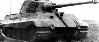
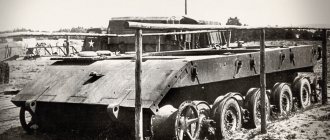
German tank "Royal Tiger"
In March 1944, a new modification of the Tiger tank, the Pz.Kpfw VI Tiger II "Königstiger", was put into serial production. Before the end of the war, German industry managed to produce about five hundred “Royal Tigers”.
"Royal tiger"
This vehicle differed from the Tiger I in its sloping armor, which provided better protection. The disadvantages of the Königstiger were the insufficient engine power for such a high combat weight, as well as the associated unreliability and poor driving performance.
How much did the German Tiger II tank weigh? 68 tons.
Ammunition.
Since the German theory of tactical use of tanks assumed the widespread use of tank guns in the interests of countering enemy armored vehicles, several types of shots with BS were created for the gun:
- Panzergranate 39. The most common were BS with an armor-piercing head and a ballistic tip - Panzergranate 39. Just like the bulk of BS from the 2nd World War, it was chambered, that is, inside it there was a small explosive charge, which was initiated after breaking through the armor of the enemy tank . According to the German leadership, it was believed that it was capable of hitting absolutely all types of armored vehicles, at all reasonable distances.
- Panzergranate 40. Sub-caliber BS with a tungsten core. This type of armor-piercing projectile usually has a high initial velocity and therefore high armor penetration. However, there were also disadvantages - due to the lighter weight of the projectile, its characteristics - armor penetration and accuracy - dropped sharply; tungsten, which made up the projectile core, was available in extremely limited quantities.
As a result, they tried to save ammunition.
Armor penetration of the 8.8 cm Kwk 36 gun.
Pzgr. 39 Pzgr. 40 Gr. 39HL Projectile weight
(Kg)10.2 7.3 7.65 Initial speed
(m/s)773 930 600 Distance 100 m 120 mm 171 mm 90 mm 500 m 110 mm 156 mm 90 mm 1000 m 99 mm 138 mm 90 mm 1500 m 91 mm 123 mm 90 mm 2000 m 83 mm 110 mm 90 mm Probability of hitting a target measuring 2 x 2.5 m.
Projectile Pzgr. 39 armor-piercing caliber Pzgr. 40 subcaliber Gr. 39 HL cumulative Distance (m) At the training ground (%) In battle (%) At the training ground (%) In battle (%) At the training ground (%) In battle (%) 100 100 100 100 100 100 100 500 100 100 100 100 100 98 1000 100 93 100 89 94 62 1500 98 74 97 66 72 34 2000 87 50 89 47 52 20 2500 71 31 78 34 — — 3000 53 19 66 25 — —
German designers also developed a cannon cumulative projectile. In addition to its main purpose, it was believed that the cumulative projectile had a sufficient fragmentation effect. According to the German leadership, the scattering of fragments was 20 meters to the sides and 10 meters forward and had a very sensitive fuse. This ammunition was considered effective when firing at anti-tank guns, artillery crews, loopholes, machine gun nests, vertical walls of bunkers and manpower.
The gun's ammunition is completely interchangeable with that of an anti-aircraft gun, with the exception of the primer sleeve.
The Tiger tank was equipped with ninety-two rounds of ammunition. Sixty-four of them were stored in bots below the turret level in the fighting compartment. There, under the polycom, there are four more shots in four containers.
Having used up the “first shot”, before each subsequent shot, it was necessary to rotate the turret 90 or 180 degrees in the direction of the tank so that the loader could get a shot from the right or left side ammunition rack.
This process was most cumbersome and inconvenient in the command modification of the Tiger tank, because an additional generator was mounted on the right side of the fighting compartment, which also led to a reduction in the ammo capacity to 66 rounds.
German tank "Tiger" / "Tiger II" in modern museums
Very few authentic German heavy Tiger tanks survived into the 21st century. There is one Tiger I in museums in the UK, USA, and Germany; two each in France and Russia.
"Royal Tiger" at Bovington Museum, England
There are two Tiger IIs in museums in the UK, one each in Germany, Belgium, Switzerland, France, Russia and the USA.
Assembling a German Tiger tank from Zvezda becomes the first step in this hobby for many novice modelers.