Er-2 Dimensions. Engine. Weight. Story. Range of flight. Service ceiling
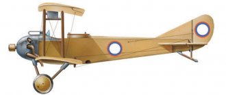
The aircraft, which in the future became the Er-2 bomber, has its own interesting history. At the end of August 1939, the Stal-7 aircraft took off from the Shchelkovo airfield. To the crew of N.P. Shebanov had to set a world speed record on a 5,000 km route. The passenger plane covered a distance of 5068 km in 12.5 hours at an average speed of 405 km/h, which significantly exceeded the previous record of pilot V.K. Kokkinaki on a TsKB-30 plane. The crew was solemnly welcomed in Moscow, and the creator of the aircraft, R.L. Bartini at this time was “rewinding” his ten years on a prison bunk with the label “enemy of the people.”
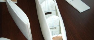
The design of the Steel-7 aircraft was started by R.L. Bartini in 1933, in accordance with the requirements of the Civil Air Fleet State Administration. In its final form, the result was a rather original aircraft with a “reverse gull” wing. This design made it possible to install engines and a lighter landing gear at the fracture site of the wing. The first flight and factory tests, which began at the end of 1936, were carried out by pilot E.I. Schwartz. However, the arrest of R.L. Bartini slowed down all work on the passenger plane. Then Bartini ended up in TsKB-29 of the NKVD, where, under the leadership of A.N. Tupolev was developing the 103 bomber. Bartini refused to work with Tupolev, and as a result, all employees of TsKB-29 were released early, and Bartini completely “rewinded” his sentence, and in addition was demoted for another five years.
The conversion of the Stal-7 passenger aircraft into the Er-2 (DB-240) bomber was carried out under the leadership of engineer V.G. Ermolaev, chief assistant to R.L. Bartini. The Stal-7 aircraft had excellent flight characteristics and was promising in its parameters. It had excellent aerodynamic properties and high weight efficiency. The DB-240 aircraft was built in accordance with the resolution of the Defense Committee of July 29, 1939. The task was to create a long-range bomber with M-106 engines with a power of 1000 hp. at an altitude of 6000 m. But the development of this engine was delayed, and then less powerful M-105 engines were installed on the first machine. In August 1939, the bomber mock-up was defended. Despite the external similarity of the DB-240 to the Stal-7, the bomber became a completely different machine, retaining only its aerodynamic configuration. First of all, it turned into an all-metal monoplane with a two-fin tail. The new fuselage had two crew cabins and a bomb bay. Defensive armament consisted of a BS machine gun in the upper turret and two ShKAS in the bow and hatch installations. The bomb bay housed bombs of various calibers, including the largest domestic FAB-1000 bombs.
The Er-2 (DB-240) aircraft made its first flight in 1940, piloted by the crew of N.P. Shebanova. The state tests carried out revealed a number of comments: the fuel tanks on the vehicle were not protected, which means that if they were shot through, a fire could not be ruled out; there was no heating for the crew cabins and no anti-icing devices for the airframe and propellers. Following the first prototype, aircraft with AM-37 and diesel M-40F engines were built. The aircraft with the AM-37 engine significantly exceeded all domestic Soviet serial bombers in speed, but due to the lack of mass production of engines, it was not built in series. The aircraft with the M-40F also required fine-tuning, but it remained experimental. The main drawback of the DB-240 aircraft was its long takeoff run, which limited its deployment location, but it was nevertheless put into production. A large series of aircraft with the ACh-30B diesel engine was also built. In accordance with the order of the NKOP dated December 9, 1940, DB-240 was renamed Er-2. Er-2 aircraft actively participated in the Great Patriotic War. A total of 391 vehicles were built, the last one leaving the assembly shop in 1945. V.G. died in 1944. Ermolaev, and a small team of designers handed over to P.O. Sukhoi. One of the production machines was used in flight tests to fine-tune pulsating engines for V.N. Chelomeya. Some of the aircraft were used in civil aviation.
Literature
- Irkutsk Aviation Plant during the war // Takeoff. 2015. No. 5;
- Khvoshchevsky G.I. Pages of the history of aircraft plant No. 39 named after. Menzhinsky: from Moscow to Irkutsk: chronicle-documentary history. Irkutsk, 2012;
- Shavrov V.B. History of aircraft designs in the USSR 1938–1950. M., 1994.
V.V. Ignatenko
The article was prepared for the Encyclopedia of the Irkutsk Region. Published for public review purposes. You can make your comments on the Irkipedia website or send the editors of the Encyclopedia to the following address:
Performance characteristics of Er-2
— Chief designer: V.G. Ermolaev - First flight: May 14, 1940 - End of operation: end of 1946 - Units produced: 462
Er-2 crew
— 4-5 people
Dimensions Er-2
— Length: 16.23 m — Wing span: 21.65 m — Height: 4.82 m — Wing area: 72.1 m² — Leading edge sweep angle: 13° — Wing transverse V: +7° — Load on wing: 166 kg/m²
Weight Er-2
— Empty weight: 7,076 kg — Curb weight: 12,000 kg — Maximum take-off weight: 13,460 kg — Fuel tank capacity: 5440 l
Engine Er-2
— 2× M-105 water cooling — Power: 2× 1100 hp (809 kW) — Propeller: VISH-22E with a diameter of 3 m — Thrust-to-weight ratio: 140 W/kg
Speed Er-2
— Maximum speed at altitude: 445 km/h — Maximum ground speed: 395 km/h — Cruising speed: 390 km/h — Climb rate: 5.5 m/s — Takeoff length: 580 m (with a weight of 11,300 kg)
Flight range of Er-2
— 4,100 km
Practical ceiling Er-2
— 7,700 m
Armament of Er-2
Machine gun: - 1x 12.7 mm machine gun in the upper fuselage turret, 400 rounds - 2x 7.62 mm machine gun in the nose (500 rounds) and in the hatch under the fuselage (1075 rounds)
Bomb load: - normal: 1,000 kg - maximum: 5,000 kg (for later modifications)
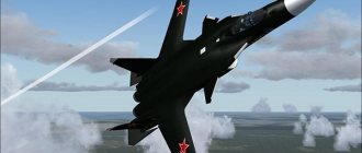
The Er-2 aircraft (Ermolaev) is a classic monoplane with an empennage consisting of two fins, as well as a landing gear with two wheels on the tail support.
Airplane fuselage.
The fuselage of the aircraft is all-metal, monocoque type. Technologically, it was divided into nose, middle and tail sections, the fairing of the tail section. The fuselage frame consisted of forty frames and thirty-six solid stringers. In addition to the uncut stringers, four spars ran along the fuselage: two along the bottom of the fuselage, and two along the sides. The frames (excluding the first, tenth and fifteenth), spars and stringers were made of duralumin profiles. Between the tenth and fifteenth frames, the longitudinal frame was strengthened with double stringers. In the central compartment of the aircraft, external spars were installed on each of the two sides.
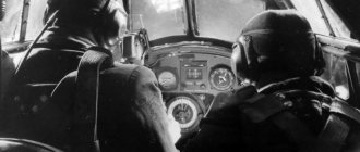
At the front of the aircraft were the cockpits of the pilot and navigator. The pilot's seat was located on the left between the sixth and eighth frames. The floor of the cabin was a pedestal, the frame of which was riveted from duralumin profiles and covered with thick plywood. The navigator's seat was mounted on the right. A bow gun mount was installed on the ring of the first fuselage frame. The forward part of the fuselage also contained aircraft controls, instrument panels and other equipment.
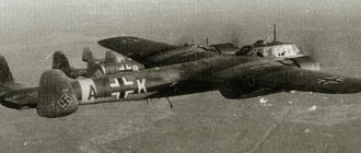
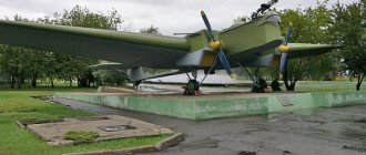
Airplane Er-2 documentary photo
In the middle part of the fuselage there were fuel tanks and bomb weapons. Between the eighth and tenth frames, four fuel tanks were mounted, two of which were installed at the top, and the other two were attached to special patterns on the right and left sides so that a technical corridor remained between them. The bomb bay was located between the tenth and fifteenth frames. Its hatch was divided by a central beam into two halves, right and left. The hatch doors were closed by cables, and opened by spring pushers. The bombs were placed so that the central beam provided passage to the rear of the aircraft. Two more fuel tanks were suspended above the bomb compartment. The gunner and radio operator were located in the rear fuselage. The radio operator's seat was located on the left side between the fifteenth and sixteenth frames. A radio station was mounted behind it on the starboard side. The gunner's seat was located in the upper shooting mount, placed between the twenty-first and twenty-fourth frames in a special hatch.
There was a hatch in the wooden floor of the rear fuselage, intended for the crew to enter and exit the aircraft and fire from the hatch installation. The hatch was locked from the inside with a lid. The stabilizer was attached to the thirty-third, thirty-fifth and thirty-seventh frames; the edging of the cutout was reinforced along the contour. The tail fairing was attached to the thirty-seventh frame. It contained a nest for storing a crutch wheel. The engine compartment was attached to the power frames (tenth and fifteenth). The frames of these frames were welded from steel pipes. The fifteenth frame was covered with a wall made of duralumin; there was a door in the center. The door frame was riveted from profiles of the same metal, and the trim was made of plexiglass. There was a similar door on the eighth frame. Both doors are of a sliding type; when opening and closing, they moved thanks to rollers along the guides. Reinforced contour frames were made from two duralumin channels mounted together with tape. The fuselage was sheathed with duralumin sheets 1-1.2 mm thick. Between the fourteenth and seventeenth frames, reinforcing 1.5-mm sheets were placed on top of the main skin. The riveting was hidden, the skin sheets were applied end-to-end to the frame. The radio operator and gunner's cabins were also glazed with plexiglass.
Airplane lantern.
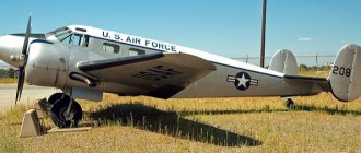
Er-2 side view
The frame of the navigator's canopy is welded, the glazing is made of plexiglass. To create a smooth surface of the lantern, the glass along the contour was milled to the thickness of the edging. At the top of the canopy there was a hatch for astronomical purposes, which opened into the fuselage. Between the second and fifth frames at the bottom there was an entrance hatch located to the left of the fuselage axis. The navigator's cabin had plexiglass windows. There were movable windows on both sides. The pilot's canopy, shifted to the left side, was made from fixed and moving parts. The frame was made of metal pipes, to which plexiglass glazing was attached with screws using external duralumin edging and special clamps. As on the navigator's canopy, the plexiglass was milled along the contour to the thickness of the edging. The moving part of the lantern with the window moved along guides on rollers. The left window of the moving part is opening.
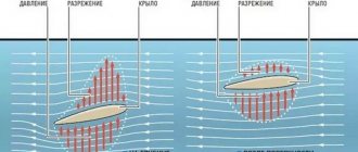
Airplane wing.
The wing is a cantilever, two-spar, “reverse gull” type. The plan had the shape of a trapezoid with rounded ends. Each half-wing was divided into an engine compartment and consoles. The connection of the wing engine compartment spars with the tenth and fifteenth fuselage frames was carried out using butt combs and cone bolts. The spars of the engine compartment and consoles were also connected using butt combs and cone bolts. Between the spars of the cantilever part of the wing there were three gas tanks, which were mounted and dismantled through the lower hatches. In the cantilever part of the wing, an engine radiator with an air intake in the leading edge of the wing was installed through a hatch in the lower skin. Its lower edge was movable. The outlet from the radiator duct louvers was located on the upper surface of the wing behind the rear spar. Ailerons and flaps of the Schrenk type were mounted on the trailing edge of the consoles. The ailerons of the Frize type were divided into two compartments connected by a loop. The aileron frame made of duralumin was a box-section spar and ribs. The toe was sheathed with sheet duralumin, and the rest with canvas. Cast iron weights for weight compensation were placed in the toes of the second aileron compartments. Each aileron was suspended from the wing on four brackets. The aileron of the left wing console had a trimmer compensator, controlled from the pilot's cabin. An oil radiator was located behind the front spar of the engine compartment. The air that cooled it entered through a channel inside the compartment. On the lower surface of the engine compartment there was a shield intended for landing the aircraft.
Airplane control.
The tail of the glider is two-finned. The cantilever horizontal tail had a transverse V=7 degrees. The elevators were suspended separately from the stabilizer and had weight compensation and trimmers. Rudders with weight compensation were hung on the keels. The right rudder was equipped with a trimmer. The control of the rudders, ailerons and flaps is rigid, the trim tabs are controlled by cable, and the landing flaps are hydraulically controlled. The pilot's control column was mounted between the sixth and seventh frames of the fuselage. The navigator also had an aircraft control station with a handle and pedals. The navigator's control lever was connected by rigid rods to the pilot's control column controls. The control wheels for the rudder and aileron trim tabs were installed to the right of the pilot. The elevator trimmer was deflected using a steering wheel located on the left side near the instrument panel.
Airplane landing gear.
The landing gear is tricycle, with a tail wheel. The main supports were retracted back into the engine nacelle fairing, while the wheel was placed between the side members of the engine compartment and protruded outward. After raising the chassis, the hatch flaps were automatically closed. The control of raising and releasing the landing gear was hydraulic, the emergency release was mechanical. The struts had oil-pneumatic shock absorbers. The wheels of the main supports are semi-balloon, 1100x400 mm in size, with two pneumatic-hydraulic brakes. The chassis position alarm is electrical. Crutch - oriented, with oil-pneumatic shock absorption; the wheel is a balloon type, measuring 400x150 mm. The crutch installation was retracted back into the fuselage niche.
Aircraft power plant.
The aircraft's power plant consisted of two liquid-cooled M-105R engines with metal three-blade variable-pitch propellers VISH-22E with a diameter of 3 m. The thrust vector of the propellers was directed at an angle of -1 degree to the chord of the wing. The engine unit was covered with a fairing, which included a propeller spinner, a hood and a chassis fairing. The propeller spinner consisted of front and rear parts. The front part had outer and inner fairings, which formed an annular channel between themselves for blowing the engine and its components in flight. The hood was made from the front ring, five beams and six covers that provided access to the engine. The sub-engine frame was welded from steel pipes. The engines were equipped with ejector-type exhaust pipes - one for three cylinders. The engines were started with a compressed carbureted mixture using a pneumatic self-starter. Compressed air was stored in cylinders, which were charged from an airfield cylinder by a drive compressor (while the engine was running). The use of a manual compressor was also provided.
The fuel was placed in fourteen protected tanks with a total capacity of 5440 liters, forming the right and left wing and fuselage groups. There were three tanks in the fuselage, and four in the engine compartment and wing console. The tanks are welded, made of AMTSM alloy. The engine mounts and main landing gear were attached to the wing engine compartment. Between its side members there was a gasoline tank, inserted from below. The removable sock contained an oil tank, installed together with the sock and held in it by tapes. The plane had a combined system for draining and filling gas tanks with carbon dioxide. It prevented the formation of a vacuum in them and protected them from ignition when shot by incendiary bullets. Oil tanks with a capacity of 380 liters, welded from AMCM and covered with a tread, were located in the leading edges of the engine compartments.
Aircraft radio and electrical equipment.
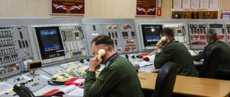
The radio and electrical equipment included an RSB-bis radio station, an RPK-2 radio semi-compass and two GS-650 generators installed on each engine. A 12A-30 battery operated in parallel with the generators. The aircraft had a Y-shaped rigid three-beam antenna with a retractable mast under the fuselage. To ensure night flights, the aircraft had navigation and tail lights, two PR-8 parachute rockets (between the 25th and 26th frames) and an FS-240 headlight (500 W) in the toe of the left wing console. Communication between crew members was provided by the SPU-4bis intercom, three-color alarm lamps and sirens. The cabins of the navigator and gunner-radio operator were connected to each other by a pneumatic mail, powered by an incoming air flow. The PVD tube and clock in each cabin were heated with electricity. The crew members had electrically heated overalls (including insoles and gloves).
Aircraft oxygen equipment.
There were four KPA-3bis oxygen devices on board. The supply of oxygen was stored in eight 12-liter cylinders (two per device). It was enough for 8 hours of flight at an altitude of 8000 m. The cylinders were located in the rear fuselage. There, between the 26th and 27th frames on the floor there was a nest for installing an AFA-B camera.
Aircraft fire fighting equipment.
The fire-fighting equipment included two cylinders with carbon dioxide installed under the pilot's floor in front of the control column, two cylinders with carbon tetrachloride in the wing engine compartments, sprayers located on the fire barriers, and pipelines. The aircraft also carried a flare gun and an outside air thermometer.
Aircraft armament.
Bomb armament was placed on both internal and external slings. There were six cassette holders in the bomb bay: in the front and rear parts there were two KD-2-240 (for bombs with a caliber of up to 100 kg), and in the middle there were two KD-3-240 (from 250 to 500 kg). On the CD -2-240 it was also possible to hang ABK-240 ampoule cassettes (two for each). In addition, bombs could be suspended on two external beams Der-19-20 (for bombs up to 1000 kg). The normal bomb load in the bomb bay did not exceed 1000 kg and was allowed in the following versions: 10xFAB-100 or 4xFAB-250 or 2xFAB-500. The maximum that could be placed inside the fuselage: 12xFAB-100, or 4xFAB-250, or 4xFAB-500 . The bombs were suspended from internal cassette holders using a BL-4 manual winch located in the radio operator's cabin.
Outside, it was allowed to hang two bombs of caliber from 100 to 1000 kg or two pouring chemical devices VAP-500U or UKAP-500. The maximum bomb load reached four tons. Bombing was carried out during the day using an OPB-2M sight with electrical heating, and at night - NKPB-3. To drop bombs there was an ESBR-5 electric release device and an emergency mechanical ASSh-340. The latter was installed between the navigator and the pilot, so both could use it. The defensive armament of the Er-2 consisted of three machine guns. In the forward part of the fuselage there was a DB-3F type installation, on which a 7.62-mm ShKAS machine gun was mounted in a ball joint. The latter was powered by a collapsible belt from a box with 1000 rounds of ammunition. The spent cartridges and links were collected in a bag attached to the machine gun.
In the lower hatch there was a retractable MV-2 installation with a second ShKAS machine gun. In the stowed position it was hidden in the fuselage, but in the combat position it went down (the hatch had to be opened first). The shooter fired from his knee, aiming through the OP-2L periscope sight. The part of the installation protruding into the flow was covered with a fairing, the side flaps of which were made of plexiglass. The limiter pin prevented the barrel from being pointed at the tail wheel. The machine gun was powered by a belt from a box containing 1000 rounds. On top of the fuselage was a shielded TAT-BT turret with a 12.7 mm BT machine gun. It had a retractable aerodynamic compensator. The machine gun was fed from interchangeable magazines, each with a belt for 40 rounds. The ammunition included five magazines, four of which were placed in niches on the sides of the fuselage.
Back - Forward >>
| < Back |