La-11 Dimensions. Engine. Weight. Story. Range of flight. Service ceiling
Continuing to improve its fighters, OKB S.A. Lavochkin built a new aircraft “134” (La-9M) on the basis of the La-9. The first flight on it in May 1947 was performed by test pilot A.G. Kochetkov, who transferred to the design bureau from the Air Force Research Institute. Five days later, a second copy of the 134D with a longer flight range appeared at the Chkalovskaya airfield. Additional fuel tanks were equipped in its consoles; as a result, its fuel supply increased from 825 to 1100 liters.
The two experimental versions of the aircraft, “134” and “134D,” differed from the La-9 by having an oil cooler built into the engine hood and the number of NS-23 guns being reduced to three. The propeller-motor group of these modifications was a single complex. The gun embrasures and the oil cooler air intake were organically integrated into the hood of the ASh-82FN engine, which noticeably reduced the overall resistance of the vehicle in flight.
The 134D aircraft, intended to escort bombers, had an additional oxygen tank and a urinal. The seat was equipped with adjustable armrests and a wide soft back. The weight of the vehicle led to a decrease in flight performance. In July 1947, test pilots I.M. Dzyuba and V.I. Alekseenko completed two long-distance flights at different speeds. The technical range was determined from the condition that during the flight along the route there would be two air battles lasting 10-16 minutes. One flight lasted 4 hours 54 minutes, the other - 2 hours 47 minutes. Despite the continuity of the 134 and La-9 fighters, tests revealed more than a hundred defects in the new aircraft. But the car was still recommended for mass production under the name La-11.
Serial production continued until 1951, in total about 800 vehicles were produced in various versions. In 1946 S.A. Lavochkin is summoned to the Kremlin. In the same year, the first MiG-9 and Yak-15 jet fighters took off in our country. I.V. Stalin asks Lavochkin a direct question: “Which aircraft should be launched into production, the MiG-9 or the La-11?” Semyon Alekseevich answered Stalin: “I think it’s a MiG-9.” Stalin clearly provoked Lavochkin when, during the conversation, he pointed to the already modified La-11 and the still “raw” MiG-9, but Lavochkin did not change his opinion. Not everyone at that moment, at that level, would have been capable of something like that.
In 1948, the idea arose to use La-11 fighters to protect the polar regions of the USSR. At that time, several scientific expeditions of the USSR Academy of Sciences were working in the North Pole area. It was decided to fly the La-11 group to one of the ice floes used by scientists. Three planes made a safe landing on the ice floe. After completing several flights from the ice floe, they returned back. After these flights, La-11s began to regularly keep watch to protect our northern borders. To do this, it was necessary to install an anti-icing system on the planes, improve navigation equipment and ensure take-off from unrolled snow strips.
La-11 fighters even took part in military operations. In 1951, by decree of the Council of Ministers, China received 60 La-11 aircraft. On them, Chinese and Korean pilots repelled American air raids on peaceful North Korean cities. There they won several victories over American aircraft, but they were unable to defeat the B-29. After all, the Yankees flew at altitudes of about 10,000 m, and to reach such a height, the La-11 needed 26 minutes. In the USSR, La-11 fighters participated in the interception of American reconnaissance aircraft. On April 8, 1950, the La-11 flight took off to intercept the target. The American plane did not obey the Soviet pilots who ordered it to land, and they opened fire. As a result, nine crew members died.
Survivors[edit]
China[edit]
- La-11 displayed at the China Aviation Museum, Datanshan, China as Red 24
- La-11 on display at the Beijing Air and Space Museum, Beijing, China, designated Red 09
Indonesia[edit]
- La-11 F-911
on display at the Indonesian Air Force Museum, Adisutjipto AB, Yogyakarta
Russia [edit]
- La-11 on display at the Nizhny Novgorod Military Museum, Russia
United Kingdom [edit]
- La-11 20
, stored awaiting restoration by The Fighter Collection, Duxford, Cambs
United States[edit]
- La-11 10142/N2276Y
, stored awaiting restoration at Kermit Weeks, Orlampa, Florida
Performance characteristics of La-11
— Chief designer: S. A. Lavochkin — First flight: May 1947 — Years of production: 1947 — 1951 — Units produced: 1,182
La-11 crew
- 1 person
Dimensions of La-11
— Length: 8.62 m — Wing span: 9.80 m — Height: 3.47 m — Wing area: 17.59 m²
Weight of La-11
— Empty weight: 2770 kg — Normal takeoff weight: 3730 kg — Maximum takeoff weight: 3996 kg — Fuel weight: 846 kg
Engine La-11
— 1 PD Shvetsov ASh-82FN — Power, hp: 1 x 1850
Speed La-11
— Maximum speed at altitude: 674 km/h — Maximum speed at ground: 562 km/h — Rate of climb: 758 m/min
Flight range of La-11
— 2235 km
Practical ceiling La-11
— 10,250 m
Armament of La-11
— 3x23 mm NS-23 cannon (ammunition — 225 rounds)
Links[edit]
Notes
- ↑
Gordon, Efim (2003). Lavochkin piston fighters. A red star. 10. Earl Shilton, Leicester, UK: Midland Publishing. ISBN 1-85780-151-2. - Details of the accident – VR-HEU – Information about the plane crash
- VR-HEU Passenger Account: Valerie Parish Archived January 27, 2009 at the Wayback Machine - Major Commercial Airline Disasters.
- VR-who Archived 2008-08-20 at the Wayback Machine - The Life and Times of James Harper
- Hong Kong - Plane Survivors Archived 2011-07-27 in the Wayback Machine - News sound film
- Gladniker, David. "An Incomplete Guide to Using an Airfoil". m-selig.ae.illinois.edu
. Retrieved April 16, 2022. - https: //www.m
militaryfactory.com/aircraft/detail.asp?aircraft_id=651
Bibliography
- Gordon, Efim. Lavochkin's piston fighters (Red Star Volume 10)
. Earl Shilton, Leicester, UK: Midland Publishing Ltd., 2003. ISBN 1-85780-151-2. - Copenhagen, W (ed.), Das große Flugzeug-Typenbuch
(in German). Transpress, 1987, ISBN 3-344-00162-0
External links [edit]
| Wikimedia Commons has media related to Lavochkin's La-11 . |
- Walkaround La-11 Fang
- https://web.archive.org/web/20110605030336/https://www.aviation.ru/La/#11
| vteLavochkin's Airplane | |
| Fighters |
|
| Experimental aircraft |
|
| Another |
|
The original version of the article was based on materials from the website aircraft.ru. It was released by the copyright owner under the terms of the GFDL.
I. AIR AIR CONSTRUCTION
Fuselage
The frame of the front part of the fuselage consists of seven main (No. 1-7) and three additional (No. 1a, 2a, 5a) frames, three semi-frames, which are continuations of frames No. 5, 6 and 7, two upper and two lower spars, six main and four additional stringers.
The frame of the rear fuselage consists of nine frames (No. 7a - 15), two additional frames (No. 9a and 10a), fourteen stringers, two upper and two lower spars. The fin is made in one piece with the rear part of the fuselage and consists of a spar, six ribs and one end rib.
On the left side of the fuselage, between frames No. 9 and 10, stringer No. 4 and the lower spar, there is a side hatch. The hatch is closed with a hinged lid.
All frame elements are connected to each other with rivets through angles and brackets. The frame of the tail section and keel is covered with duralumin sheathing made of D17ML1,2. The sheathing sheets are connected to the frame elements with countersunk rivets.
Spars
The spars of the front and rear parts of the fuselage are made of sheet duralumin grade D17M and have a cross-section that varies along the length. The upper spars of the front part of the fuselage have a C-shaped section and are made of a 3.5 mm thick profile; maximum section dimensions 60 × 46 × 30 mm.
The upper and lower spars of the rear fuselage have an angular section that varies along their length. The maximum cross-section of the upper and lower spars of the tail section is 40 × 40 mm; minimum cross-section 16 × 16 mm.
The spars are made of D17M brand duralumin profiles with a thickness of 3 mm.
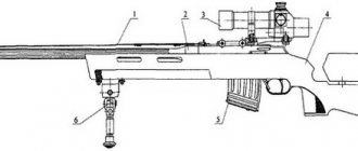
Carriage
The carriage (Fig. 9) is a steel truss welded from 30KhGSA chromansil pipes, to which the engine mount and aircraft armament are attached.
The carriage consists of two longitudinal pipes, two braces, a panel and brackets. Pipes and braces with a cross section of 40 × 35 mm. The box section panel is made of 2mm steel. All elements of the carriage are gas welded and heat treated. At the junction of the longitudinal pipes and struts, attachment points for the motor frame and stiffeners are welded. The bushings, brackets and brackets necessary for installing weapons are welded to the panel.
Flashlight
installed between frames No. 2 and 7 of the fuselage. The lantern consists of a visor, a sliding part of the rails and a fixed rear part. The frames of the visor, sliding part and rear part of the lantern are welded from steel pipes of grade 12GlA and glazed with plexiglass: the visor and sliding part are 5 mm thick, and the rear fixed part is 4 mm thick. The lantern glasses are fastened to the frames and bases using bolts with a diameter of 3 mm with a countersunk head and external duralumin edging. The visor is fixedly bolted to the front side of the cabin. To protect the pilot's head, 60 mm thick armored glass is installed in the front visor.
The visor of the lantern provides for the installation of an S-13 photo machine gun, for which purpose a steel plate with a window for the lens is mounted on the visor. The plate window is closed with a plug, which is removed when installing the machine gun. The plate is fastened to the canopy frame and to the plexiglass with bolts, and rubber sealing gaskets are installed at the joints with the canopy.
The rear part of the canopy occupies a place between frames No. 5 and 7 of the fuselage behind the cockpit and is also fixedly attached to the fuselage skin.
To access the radio equipment and the hydraulic tank, in the rear of the lantern on the left side there is a hatch with a hinged hinge, the lid of which is locked at the bottom with Dzus locks and one spring lock.
To protect the pilot's head from behind, between frames No. 5 and the frame arch of the rear part of the canopy, armored glass 9, 73 mm thick, mounted in steel brackets, is installed.
Cabin ventilation
The aircraft is equipped with a ventilation device that allows you to regulate the air temperature in the cabin. The upper ventilation device is installed on the right side of the canopy (Fig. 14) and consists of a cast intake and a distributor with holes. The distributor is located in front of the sight. The air entering the intake is directed to the distributor and passes through the openings of the latter into the cabin, creating a refreshing flow. To regulate the amount of incoming air, a valve is installed on the intake.
| >>