Description of design
Compiled by a group of tech. descriptions of the plant named after. Ordzhonikidze. Moscow 1945
1
This description is compiled according to the serial drawings that were in force when the first series of the La-7 aircraft were launched into production.
For technical reasons, not all design changes (for example, in the suction system, oil system, etc.) could be included in this publication. In the future, these changes will be published in factory operational* bulletins.
The description is compiled in sufficient detail for all units and can be used as a guide in Air Force schools when studying the La-7 aircraft.
LA 7
Fuselage: I assembled the frame practically unchanged, only entirely from the ceiling and the motor mount has a double ceiling.
Now I would do this: 6,7 single-layer frames, cut holes between 5,6,7. The shelf for the battery and everything connected to it and the rectangle made of plywood are thrown away, the side walls of the battery compartment are made double (the second layer is on the outside). Motor frame single-layer ceiling + plywood. Sheathing: (backing 3mm) The template is a little short, it is necessary to add about 5mm at the front and back (in front, most likely, and behind the engine mounts), the flats in the area of 5 frames generally had to be cut off, but it’s even a miscalculation to sheath. Internal contours: cockpit, hatch, empennage, do not need to be cut out, just outlined to simplify work in the future. We mark the centers on the casing and frame, then carefully tighten the frame, fix it with tape and leave it for a while so that the casing takes shape.
Then we cut the tape along the seam, coat the frame with glue and fix it back with tape and set it aside for a while. Plumage: Everything is simple with the keel, cut it out, carefully bend it, glue it together. But I redesigned the stabilizer a little; according to the author’s idea, the stabilizer was supposed to be mounted on bamboo skewers, I didn’t like it and I made their fastening similar to the Keel. The modification looks something like this:
Then we attach the steering surfaces of the PB loops 2 at a time, the bottom PH 3 is glued into the frame. I glued the PB bracket later, Nylon hinge loop 16x28.5 (10 pcs). In the skin we pass straight holes for the tails (relative to the axes of the aircraft) and glue them. The stabilizer consists of two parts and is joined to the frame; this method simplifies the alignment of the stabilizer when gluing.
The hood was lengthened, two more layers were added (A), it is attached to 4 magnets, two in the fuse, two in the hood and two guide pins.
The motor is attached to a piece of a ruler glued to the titanium fusel with a slight shift up and to the left so that the tilt of the motor is not noticeable. Cabin canopy using bottle technology. It's boring and dirty. The holes for the RV and RN rods were pierced with a barbecue skewer, a bad idea, it is better to do this while sheathing the frame. Wire rods for a welding machine, thickness 1mm (not enough rigidity!!!) And here’s why it’s bad:
The homemade hogs are cut from a cable channel, the rod clamps for the tail are also homemade from Klemik (by the way, the weight of such clamps is 0.9 g per pair). The wing fastenings are two small pieces of some kind of wood, turned with a knife and sandpaper, between them there is a ceiling in one layer, and on the front there are two pieces of a ruler. And on the sides this is already a renovation))).
The tail wheel stand is made of a ruler and the same wire, the wheel is purchased:
Wing: The wing spar is made from 40cm rulers; I did not make poses for the leveling. The strips for the ailerons are made from double ceiling and ground to the required shape. In the center section, the centers of the wheels were marked and pierced; after gluing the wing, I cut out the holes using a compass. The servos are glued with double-sided tape to the bottom of the wing and holes are cut for the rockers. I didn’t do the extreme level. I glued it together and tried it on.
Chassis: I made a mount from a ruler for the retraction. Retractable landing gear SMALL
Pasted as follows:
All the wooden parts were glued together by a carpenter.
Then I bent the struts and cut a groove in the wing for the struts. I installed a servo with a metal gearbox, after sharpening the retraction mechanism they move almost effortlessly, the retractors themselves are locked so that there will be no impact on the servo during takeoff and landing.
The thrust from the servo to the retraction and adjustment of the entire mechanism must be done before the final covering of the wing consoles (then it will be inconvenient). How the servo is installed and how the mechanism works in the video:
The ailerons were cut out according to a template, the ends of the ailerons and the wing were sealed with pieces of the ceiling. Loops, hogs, pulls, Linkage Stopper D1.8mm (10pcs). Then he made the cleats.
Video of the 1st flight:
The CG is a little rearward but the handling is not bad. 2nd flight moved the battery on the shelf as far forward as possible, the result was a little better, 3rd flight (at dusk) never mind the shelf, the battery flies almost right next to the motors WONDERFUL!!! It became clear that I needed speed, twists and turns. raised it higher, took off the gas, plans, but you have to steer carefully. And then I realized that he was already too far and high, I couldn’t make out what position he was in and where he was flying, I gave the gas, I tried to intuitively turn, and the ground was getting closer and closer, I took off the gas, released all the sticks and stomped in that direction of the crash.
Total:
Fuse. practically undamaged except for the wing attachment. I made a new wing. Appearance: First we painted it and covered it with tape:
This is my main assistant, she supports me in all my successful and unsuccessful affairs. Simply put, wife!!! (well, almost a wife, all that remains is to get married :) ).
Weight was about 540g. but because of the paint, the CG became rearward, as a result of which there were 3 crashes and + 25g. ballast in the form of balancing weights for car wheels. that is, the total is 565g. This didn't help much, meaning another crash. Then I decided to do it the old fashioned way, bathed the plane and covered it with colored tape. This is how the watermelon turned out:
Video of the flight (sorry for the quality).
List of completed works
I want to say that I completed all the tasks set for myself. I’ll tell you about the moments of finalizing the model. 1) Completely changed the landing gear niches: made a spar, five pairs of rib tips, added air ducts and some of the hydraulic system. 2) Modified the landing gear: I made shields of the correct shape from foil, added brake hoses, pneumatic shock absorber rods from needles, and fastening the shims to the strut. 3) I installed a PITO tube between the shields of the main landing gear, and also modified the PVD on the console with a needle of the appropriate diameter. 4) The wheels on all the racks were replaced with rubber ones from “Elf” 5) I drilled out the oil cooler air intake channel and gave the leading edge a large-scale thickness. The oil cooler scoop was replaced with an etched one. 6) Antenna stands replaced. The antenna stretch is consistent with the photographs. 7) Installed ANO glass on the consoles and launch vehicle. Modified the propeller spinner, propeller blades, and blinds. 9) Installed pipes from Model Point tubes. 10) Almost all metal cladding is made of foil. 11) Installed the toy soldiers and removed the thickness of the trailing edge of the wing. 12) The cockpit has been improved. This process is shown in the topic. 13) Made a lantern from film. See the manufacturing process there. The sliding part of the lantern can be in an open or closed position.
Armament and armor
The La-7 could be armed with 2x20 mm (ShVAK) or 3x20 mm (B-20) cannons. The guns were equipped with a hydromechanical synchronizer that prevented shells from hitting the propeller blades. Most La-7s were armed with two ShVAK cannons with 200 rounds of ammunition per gun. The ammunition load includes armor-piercing incendiary shells weighing 96.6 g (capable of penetrating armor up to 20 mm thick at normal distance from 100 m) and fragmentation incendiary shells weighing 96 g.
Bombs weighing up to 100 kg can be suspended on two underwing units (each). The most frequently used were high-explosive bombs FAB-50 and FAB-100, as well as incendiary bombs ZAB-50 and ZAB-100; 50 kg and 100 kg respectively. An 8.5 mm thick armored backrest is installed behind the pilot's seat.
Flashlight
Now we come to the main problem of the model - the flashlight. Due to the fact that I did not like not only the shape of the armored glass on the visor, but also the fact that the entire canopy has a thickness of plastic that distorts and covers the entire filling of the fuselage, I decided not to use it. Having twirled the vacuum-formed lantern from Pavla models in my hands, I was disappointed. They simply made a copy of a part from the kit. All that remained was to make the pressed flashlight yourself or go with a more complex, but very interesting method - from film for printing on a printer. I have already shown a similar technology on the Fw190S-8 model. I unwrapped the parts of the lantern in Photoshop. This method made me very happy with the opportunity to get closer in appearance to the prototype and good scale on the model. Plus it makes it possible to get not only flashlight parts, but also ideally fitting masks for both sides. Still, it was not without difficulties. The visor part turned out to be labor-intensive. It is difficult to manufacture, however, I managed to achieve an acceptable result and even wrap the armored glass into a separate binding. After finishing work on the model, I could confidently say that such a lantern is real.
__”... - Guys, who made the suit? They say: “We!...”
A. Raikin “People and mannequins”
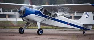
Our club cultivates areas of aerobatic models, both classical aerobatics and 3D. However, there is a direction of aircraft modeling in which we have not had the opportunity to try ourselves. This is the construction of replica models. The direction is very exciting, but requires quite high skill in both manufacturing and piloting. During this winter period, it was decided to try to build a semi-copy. Since we have little experience, after studying the materials, it was decided to build a semi-copy of the LA-7 with a span of 2 m according to the drawings available on the Internet and built more than once by aircraft modellers. The project is collective. The following requirements were presented to the aircraft
- High flight qualities allowing flights in bad weather conditions, from poorly prepared runways
- Be similar to the prototype.
- Don't have an exorbitant budget
To fulfill the first condition, self-adhesive plywood was made from sawn balsa and pine veneer. The veneer strips are carefully adjusted and glued using professional equipment. To maintain a more forward alignment, it is planned to use a non-retractable rear wheel, placing the elevator and direction servos in the central part, using hidden cable control. We plan to cover it with classic film. The model is built for the proven DLE-55 engine with “Extra-330”. If possible, we will try to use a canister. During the construction process, you want to be careful about the weight of the model.
We discuss the project on the forums
https://forum.rcdesign.ru/
https://rc-box.ru
And so we begin:
Dmitry spent 2 weeks adjusting veneer sheets in the evenings and prepared 9 sheets of pine plywood and 3 sheets of balsa plywood measuring 750 by 450 mm. Denis, through an acquaintance, used the services of a professional press and performed high-quality gluing of sheets. Placed the details on sheets.
And now the exciting moment of starting to cut parts
After 4 days of cutting work and the loss of 3 cutters, the cutting job was completed.
Now we are cutting slats from fine-grained pine; in total, more than thirty meters of various slats are needed. The stocks are being prepared for assembly.
Printed drawings in full size
November 17 The slipway for the fuselage was prepared. They provided for convenient dismantling of the racks and pipes, in case something goes wrong