Start
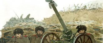
Tanks are the main striking force of ground offensive operations. It is difficult to imagine a modern army that would not have tank units. These armored vehicles first appeared in the armies of European states during the First World War. The military and engineers did not yet fully imagine what this “land cruiser” should look like. England, which was one of the first to build tanks, was once considered the “mistress of the seas.” Therefore, a characteristic feature of British tanks of that time were sponsons, borrowed from naval battleships, and a spacious diamond-shaped layout, which made it possible to move inside the tank without bending over. Such tanks vaguely resembled the captain's cabins of warships. But in 1917, the French army adopted one of the most successful tanks of the First World War - the Renault FT-17. It became the first tank of a classical layout and the first to have a circular rotation turret.
Renault FT-17
Renault FT-17 has been adopted by many countries. Its release was launched not only in France. In Italy, the tank was produced under the name FIAT 3000, and overseas, in the USA, - M1917 (Ford Two Man). They copied it and put it into production in the Soviet Union. It was known as “Renault-Russian”, “Tank M”, “Tank KS” and even “Tank “Freedom Fighter comrade”. Lenin." It became the first Russian and first Soviet tank to go into mass production. Very different from his contemporaries, he defined what tanks would look like for the next hundred years.
How the legendary tank of the Great Patriotic War T-34 works
The birth of the "thirty-four"
From about mid-1931, wheeled-tracked high-speed tanks (BT) or BT of various modifications began to enter service with the Red Army. These tanks were not much different from their ancestor - the American tank created by Walter Christie. The main advantage of the BT series vehicles was their high maximum speed and maneuverability, the ability to move on both tracked and wheeled vehicles. BT-2 and BT-5 received their first baptism of fire in 1936 during the Spanish Civil War, followed by the Soviet-Finnish War.
Despite the overall successful use of the vehicles, there were also many complaints about them: the armor protection was clearly insufficient, and the gun was weak. Moreover, Soviet intelligence reported on a possible conflict with Germany, which was armed with armored tanks PzIII and PzIV. The BT series of tanks required deep modernization, and in 1937 the country's leadership gave the task to the design bureau of the Kharkov plant to create a tank capable of eliminating the engineering shortcomings of the prototypes. The design of the new tank began at the end of 1937, the work was headed by the famous designer and engineer Mikhail Koshkin.
By the beginning of 1938, the new tank was ready, it received the double factory name BT-20/A-20, 25-mm frontal armor, an innovative engine, a new gun and, like its “ancestors,” could move on both wheeled and tracked vehicles. . In general, the combat vehicle turned out to be good, however, it still bore the disadvantages of its predecessors - armor of 25 millimeters could not be perceived as a worthy means of protection against guns of 45 millimeters or more. Therefore, in May 1938, at a meeting of the USSR Defense Committee, a plan for modernizing the A-20 prototype was announced - another increase in armor protection and the abandonment of wheel travel for the sake of simplicity of design.
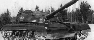
Tank T-34
The new tank received the index A-32, it was similar in weight to the A-20, but after all the upgrades it received a 76-mm cannon, reinforced armor - 45 mm - and an incredibly powerful engine that allowed the "thirty-four" to almost "dance" on the field battle. Subsequently, the latest modification was called A-34 or T-34, under which designation it went down in history. The first 115 T-34s rolled off the assembly line in January 1940, and before the start of the war their number increased to 1,110.
During the war, production of the T-34 was actually transferred to the Urals, since the Ural Tank Plant was the main backup of the Kharkov plant, which, for obvious reasons, was going through hard times. From 1941 to 1945, tens of thousands of T-34s were built in Nizhny Tagil. According to historians, every third combat vehicle was made in the Urals.
The T-34-85 modification began rolling off the Uralvagonzavod assembly line 2 months after it was put into service. In the summer of 1944, Ural designers were awarded the Order of Lenin for outstanding services in creating the T-34 design and for further improving and improving its combat qualities.
Equipment of the “miracle machine”
The T-34 had a classic layout for the Soviet school of tank building - a rear-mounted transmission. Inside, the tank was divided into four compartments - control, combat, engine and transmission. In the frontal part of the hull there were seats for the driver and radio operator, observation devices, compressed air cylinders for emergency engine starting, as well as a machine gun mounted on the frontal armor. The fighting compartment was located in the middle of the tank; there were seats for the tank commander, who was also the gunner, and for the turret gunner, who also served as a loader. In addition to the gun, the turret contained part of the ammunition stowage, additional viewing devices, and a hatch for crew landing. The engine compartment was also located in the middle, but for the safety of the crew it was protected from it by a special removable partition.
The armor protection of the hull was made of rolled sheets of homogeneous steel, located at a strong angle, which caused frequent ricochets of enemy shells. The all-round protection of the hull was 45 millimeters, which, coupled with the slopes of the armor, provided protection from guns with a caliber of up to 75 millimeters.
Tank T-34
The T-34 was armed with a 76-mm F-34 cannon, which at the first stage of the war penetrated all German tanks in any projection. Only with the advent of the “Tigers” and “Panthers” did this weapon have difficulties, which, however, were often solved by maneuverable combat. The arsenal of shells was as follows:
— high-explosive long-range fragmentation grenade OF-350 and OF-350A
— high-explosive grenade of the old Russian model F-354
— armor-piercing tracer projectile BR-350A
— armor-burning projectile BP-353A
— bullet shrapnel Sh-354
In addition to the tank gun, the T-34 was equipped with two 7.62 mm DT machine guns, which, as a rule, were used to suppress manpower in urban environments.
Tank T-34
The “miracle car” was equipped with a 12-cylinder diesel engine with a capacity of 450 horsepower. Considering the small mass of the tank - about 27-28 tons - this engine made it possible to feel equally confident in the spring-autumn thaw, in the fields, and on arable land. Military reports contain many memories of the T-34 crew members, who performed real miracles in maneuverable combat - at high speed and at a short distance from the enemy tank. For example, the feat of the crew of the T-34 modification - T-34-85 under the command of Alexander Oskin. In the summer of 1944, they destroyed three of the newest Royal Tiger tanks in a maneuverable battle. Since the frontal armor of the German “cats” was too tough for Oskin’s tank, he decided to get as close as possible to the enemy and hit him in the less protected sides, which he did with success.
Legend Upgrade
The last technical modification of the T-34 was the T-34-85 tank, which was adopted by the USSR in 1944 and legally withdrawn only in 1993. Despite the significantly changed appearance of the vehicle, only the turret was actually new, which carried a more powerful 85-mm cannon - hence the name of the tank. Due to the larger turret, the tank freed up space for an additional crew member - the gunner, which made it possible to “unload” the tank commander. The slightly increased weight was compensated by increased engine power, and the new gun became a worthy response to the Panthers and Tigers.
This latest modification of the legendary T-34 is considered the crowning achievement of Soviet medium tanks of the Great Patriotic War: the ideal combination of speed, maneuverability, firepower and ease of use. The tank was used in the Korean and Vietnam Wars, in clashes between Israel and Egypt, and in African conflicts.
In the post-war period, the “miracle of Soviet engineering” was supplied to the countries of the Eastern Bloc, Austria, Germany, China, and is currently still in service with more than 20 countries. By the way, it is the T-34 combat vehicles of the Celestial Empire that owe their appearance. In the early 50s of the last century, the Soviet Union actually donated all the documentation for the production of the T-34 to friendly China. And the inquisitive brain of the hardworking Chinese people put into production various modifications of this tank, which until recently bore the recognizable index “34” in the name.
The Soviet, and later the Russian school of tank building designed vehicles, one way or another based on the creation of Mikhail Koshkin, which was ahead of its time - the legendary T-34.
Tank T-34
Layout
Before starting to develop a new tank, it was necessary to decide on its layout solution. That is, to determine what the relative position of the main structural elements of the tank will be, and first of all the engine, transmission and crew workplaces, because the tactical and technical data of the combat vehicle and its appearance depend on this. There are three main layout solutions for modern tanks.
The layout with a rear engine and transmission is considered classic. The legendary T-34 and the already mentioned Renault FT-17 were built according to the classical design.
If the FT-17 is considered one of the best tanks of the First World War, then the Thirty-Four is considered the Second.
The turret shifted forward defines the silhouette of the tank. The control compartment is located in the front part of the tank, then the combat compartment, and then in the stern - the engine and transmission compartment. Almost all tanks ever created in the USSR and Russia were built according to this design. This arrangement is typical today for almost all modern foreign tanks.
German tanks of World War II had a different layout. “Tigers” and “Panthers” are representatives of the so-called “classical German layout”. The engine was located in the rear, the transmission and control compartment were in the bow, and the fighting compartment was in the center. These tanks were slightly taller. The driveshaft connecting the engine and transmission passed above the floor through the entire vehicle and was located under the fighting compartment.
"Tiger" - German heavy tank of the Second World War
Diagram of the internal structure of the tank. The image explains the tall silhouette of the tank
The third layout scheme involves placing the engine and transmission in the front part of the hull, and the fighting compartment in the rear. This type of tank is characterized by the turret being shifted towards the stern. A typical example is the Israeli army's Merkava MBT. The non-standard layout is explained by the fact that when developing the tank, the Israelis primarily took care of protecting the crew. Placing the crew behind the engine compartment should, in the opinion of military officers and engineers, provide additional protection to crew members. However, this circumstance causes a lot of controversy. In addition, the “war chariot” of the Israeli army (this is how the name of the tank is translated) has a compartment for landing and evacuating the wounded. And if one tank is immobilized by a shell hitting the bow, another will be able to pick up its crew. One way or another, all layout solutions have their pros and cons.
Typical solutions for the general layout of tanks: a) aft arrangement of the engine and transmission; b) forward arrangement of the engine and transmission; c) stern engine and forward transmission
Layout of main battle tanks
A tank as an engineering structure is a complex of weapons, armor protection, load-bearing base, power plant and chassis. The tank must provide the ability to move both off-road (specific ground pressure not exceeding the pressure of a person’s foot) and along the existing road network with artificial structures (full-load weight not exceeding the bearing capacity of bridge spans).
The chassis of the tank is subject to general requirements for a tracked propulsion unit, primarily ensuring a uniform load on the chassis road wheels. Ignoring these requirements leads to the following negative consequences: - reduced cross-country ability due to uneven specific pressure on the ground; — increased vertical vibrations of the body when moving over rough terrain, — decreased speed; — a decrease in the accuracy of firing from a cannon due to the lower efficiency of its stabilizer; — increased crew fatigue; — increased wear of elastic suspension elements of road wheels and hydraulic shock absorbers.
Therefore, the layout of the tank must meet the requirement of weight balance of its components relative to the center of the supporting surface of the tracks. The main massive structural elements of the tank include a gun turret, a cannon, gun ammunition, an engine, transmission and fuel, as well as armor and dynamic protection. The crew, which weighs an order of magnitude less, but occupies a large internal volume, also has a direct impact on weight balance. The relative arrangement of these elements determines the effectiveness of the combat vehicle's layout.
The first types of tanks, developed in Great Britain and Germany during the First World War, had a simple layout - a common hull casemate with weapons located in the front part (along the sides and/or in the frontal part), and an engine and transmission located in the rear part. Ammunition and fuel were located in the center of the hull. The large crew and armor protection were evenly distributed throughout the hull. There was no gun turret as such; instead, casemate half-turrets were used, symmetrically located along the sides of the hull. The tracked propulsion unit had a chassis with low-speed road wheels, as can be seen in the example of the German AV7 tank.
Experience in the combat use of tanks of the simplest layout revealed their design shortcomings: - weak armor protection of the casemate hull with a developed external surface; — the presence of large dead zones of fire from cannons installed in casemate half-turrets; — low speed of movement over rough terrain due to the small suspension travel.
In this regard, at the end of the First World War in France, the optimal layout for a new strike combat weapon was developed, which has since become a classic, repeated in hundreds of prototypes and production vehicles in many countries around the world. The hull of the Renault FT-17 tank had a very dense layout, for the first time divided into clear functional zones - the forward control compartment, the central fighting compartment and the aft engine and transmission compartment. A circular rotating turret with a 37 mm cannon was installed in the center of the hull, offset toward the nose. The control compartment housed the driver, the combat compartment housed the tank commander and ammunition, and the engine and transmission compartment housed the engine, transmission and fuel.
A development of this arrangement was the design of the Soviet KV-1 tank at the beginning of World War II, the turret of which had a developed rear niche in which a significant part of the gun’s ammunition was located. At the end of the war, the latest modification of the most popular Soviet tank, the T-34-85, received a similar turret.
In World War II, tanks were used in offensive operations in accordance with their unique combat specialization - as a means of breaking through fortified defenses, operating in direct fire contact with the enemy. In this case, the main threat of hitting the tank came from the frontal angle. This necessitated the need to differentiate protection with an increase in the thickness of the armor of the frontal parts of the hull and turret and a corresponding decrease in the thickness of the armor of the side and rear parts. The center of gravity has shifted forward relative to the center of the track's supporting surface.
In order to restore the tank's optimal weight balance, it was necessary to move its turret back. For this purpose, another innovation was introduced into the classic layout: all German tanks and the American Sherman M4 tank had a separate power plant - the gearbox and final drives were located in the bow compartment of the hull, and the engine and fuel were located in the stern. The engine was connected to the transmission by a driveshaft. This solution made it possible to move the heavy turret back at the cost of moving the relatively light transmission forward.
The last version of the tank layout had two major drawbacks: - the presence of a propeller shaft forced an increase in the height, volume and surface area of the hull, reducing the degree of protection of the tank (the ratio of the armored volume to the weight of the armor); — the final drives of the tracked propulsion placed on the frontal surface were extremely vulnerable not only to armor-piercing shells, but also fragments and shock waves from explosions of high-explosive fragmentation shells, in contrast to the classical layout, where the body shields the aft final drives from frontal fire. A solution to the problem was found at the end of the war by Soviet developers in the design of the T-44 tank. Without changing the classic layout, they reduced the length of the aft compartment due to the transverse arrangement of the engine and transmission, connected by a gear drive. The center of the track's supporting surface has shifted forward in the direction of the tank's center of gravity. Subsequently, this engineering solution (reducing the size of the power plant) in combination with a previously implemented layout option (turret with a developed aft niche) was repeated in the designs of main battle tanks of the USA, Germany, France, Japan and South Korea, including those currently in service moment.
However, a departure from the classic layout of the Renault FT-17 with the ammunition moved to the rear niche led to a weakening of the tank’s protection due to an increase in the armor volume while simultaneously creating excess space in the fighting compartment of the hull. The reason was that the height of the housing could not be reduced below the level of the engine in combination with its cooling system (approximately 1 meter). In this case, the height of the turret is determined by the extreme points of lowering the barrel (up to touching the edge of the upper frontal part) and raising the breech of the gun (up to touching the ceiling of the turret) when the gun is aimed vertically (approximately 0.8 meters). When placing the commander and gunner mainly in the turret, a volume sufficient to store all the ammunition is formed in the turret space.
The only problem is how to ensure that shots are lifted from the turret space and sent into the gun. In 1964, this problem was solved in the Soviet T-64 tank by installing an automatic loader under the rotating floor of the fighting compartment. All subsequent Soviet, Russian, Ukrainian and Chinese tanks to this day use this layout.
In 1958, the American developers of the experimental T92 tank tried to take a different route. Its original layout was based on moving the engine and transmission compartment to the nose of the hull and combining it with the control compartment, fenced off by an armored partition. The weight of the frontal armor, engine and transmission was balanced by the weight of the turret and ammunition. However, the combination of the length of two compartments of the hull at once forced us to increase its height in order to vertically arrange the power plant equipment. As a result, the tank's armor volume and hull surface area increased while the degree of protection decreased. Despite the obvious disadvantage of this arrangement and the rejection of it by American developers, it was repeated in the Israeli serial Merkava tank and the Swiss experimental NKPz tank, which is most likely due to the lack of experience in tank design in these countries.
The increasing efficiency of modern armor-piercing and cumulative shells forced developers to take the next step in improving the design of tanks. As part of the development of the classic layout, in the 1980s, work was carried out in the USSR and the USA to create experimental tanks with uninhabited turrets - the Boxer/Hammer and ASM Block III, respectively. Brought to a high degree of readiness, this work was stopped due to the lack at that time of reliable electronic surveillance and aiming equipment for the crew, located entirely in the hull.
Work in this direction was resumed only in 2012 as part of the project to create a new Russian Armata tank. Based on modern advances in the field of automatic target detection and tracking systems, the project provides for a reduction in the tank crew to two people located in the control department. In addition to the uninhabited fighting compartment and turret, a significant difference between the Almata layout and the Renault FT-17 layout is the increase in the length of the forward end of the hull in order to accommodate mounted armor or dynamic protection modules. The increased body length has a positive effect on the rearward shift of the center of the track support surface. The dimensions of the nasal tip can be estimated from a photograph of the experimental tank “Object 187”, used as a prototype of the “Armata”.
The predicted development of the functionality of promising active protection systems for tanks, up to the interception of high-speed kinetic projectiles, makes it possible in the near future to reduce the requirements for passive armor protection of a tank, as well as for its dynamic protection, which is currently successfully used against low-speed rocket-propelled grenades and anti-tank missiles. Moreover, the number of launchers of damaging active protection elements installed on each tank will ensure the simultaneous interception of two or more targets approaching from the same or different directions. Based on this forecast, we can assume the abandonment of dynamic protection, a reduction in the thickness of the armor to anti-fragmentation, and a transition to all-aspect undifferentiated armor.
In addition, today there are ready-made solutions for hybrid power plants consisting of a heat engine (diesel or single-shaft gas turbine engine), a built-in electric generator, a high-capacity lithium-ion battery and traction electric motors. It becomes possible to move the traction engines along with the final drives to the bow of the hull, distributing the load more evenly along the length of the supporting surface (taking into account the large volume occupied by the control compartment and the low weight of the two-person crew). At the same time, duplicated power cables connecting the electric generator with electric motors, unlike the propeller shaft of tanks of the Second World War, can be routed along the fender sponsons of the hull, without leading to an increase in its height.
A tank with a similar layout was already developed in 2009 as part of the American FCS program, but did not go into production due to the unavailability of the selected Quick Kill active protection system to intercept high-speed kinetic armor-piercing projectiles. However, given the progress in the development of this type of protection, it is now likely that this arrangement will be used in the American airmobile tank, the concept of which is being developed by the US Army TRADOC command, and the Israeli Rakiya main battle tank, intended to replace the outdated Merkava tank. in armored units of the Israel Defense Forces, starting in 2022.
Tower
It's hard to imagine a tank without a turret. All modern MBTs have them. The only exception, perhaps, is the Swedish Strv 103. This is one of the most widespread and recognizable representatives of tanks with a turretless configuration, which is now practically unheard of. Although some researchers classify it as a tank destroyer. But a hundred years ago, the presence of a tank on a turret did not seem an obvious fact. The first tanks did not have turrets in the modern sense. Initially, the tanks' armament - cannons and machine guns - was located in the side sponsons. As, for example, in the Mark I, the first tank in history, used at the Battle of the Somme on September 15, 1916. The Mark I became the founder of the family of British "diamond" tanks.
Only over time did the armament of tanks move from sponsons to turrets, which determined their modern appearance. The tower allows you to fire in any direction. To fire a shot, there is no need to rotate the tank's body. In addition, the 360-degree rotating tower allows for all-round surveillance. As a rule, half of the tank’s crew is in it. The commander, who can also be a gunner, and the loader are located in the turret. This is how the T-34 turret is designed. The tank crew can manually load and repair the gun, since the breech is located inside. The turret can contain an automatic loader, which reduces the crew by one person. Part of the ammunition is also located here. The main armament of the tank is installed in the turret - a cannon and a coaxial machine gun.
The Swedish turretless tank Strv 103 did not just appear out of a desire to surprise the world. Due to its large size and weight, a traditional turret is an excellent target; a successful hit is guaranteed to destroy the tank and almost always its crew. The concept of a tank without a turret appears to have little prospects. But a tank with an uninhabited turret, intended only to house tank weapons, radars and defense equipment, is a promising idea. The first mass-produced implementation of this idea was the T-14, the newest Russian main tank based on the Armata universal tracked platform. With its advent, crew accommodation ceases to be one of the main functions of the tower. The tank is equipped with an uninhabited turret, and this arrangement is considered a fire monitor.
Construction of the T-14 "Armata" turret
New in blogs
Category “Articles about the USSR” in the community “Politics, Economics, Society (without bans)”
There is perhaps no more famous tank than the Soviet T-34. Introduced in 1939, this car was not without “childhood diseases”. But the innovative design and the groundwork for subsequent upgrades made it possible to create a tank that combined ingenious simplicity with revolutionary solutions. Created in 1944, the T-34-85 model with a new gun and turret brought all the characteristics of the tank into ideal proportions. This is confirmed by the fact that the mass production of the car “outlived” all its peers (assembly took place until 1958). And its active combat use until the 1990s demonstrates that the characteristics of the tank in some conditions turned out to be “timeless.”
Location of the crew of the T-34-85 tank
Many books have been written about this tank, and just as many more will be written. We will not repeat ourselves, but simply consider the internal volumes of the tank. Let's take a look at the conditions in which tankers from many countries around the world achieved glorious victories and felt the bitterness of defeat.
Soviet troops on T-34-85 armor in China, August 1945
The crew of the vehicle consists of 5 people, and the layout is classic: with the engine and transmission compartment located in the stern, and the control compartment in the front of the hull. Let's get started!
Driver mechanic
Top view of the driver's control devices
View of the control department
Driver's dashboard
This crew member was located in the control compartment, on the left. The tank driver had access to 400 horsepower of the V-2-34 diesel engine. It was launched by an ST-700 starter, or compressed air, the cylinders of which were located behind the lower armor plate. The rotation was carried out “classically” - using two levers. In the stowed position, visibility occurred through a hatch in the frontal armor plate, and with the hatches closed, through two periscope devices.
View of the driver's seat from the fighting compartment. The hatch is open. Under the right lever you can see the compressed air cylinders that were used to start the engine
View of the driver's seat through the open hatch
View of the control levers. In the background is a folded seat and the handle of a radio operator’s machine gun.
Gunner-radio operator
In front of the radio operator's position there were racks with magazines for a DT machine gun, 7.62 mm caliber.
There was a standard fire extinguisher at the radio operator's seat.
The radio station operator operated the 9-RS device, which was previously located in the control compartment, but later moved to the tower (since 1944, that is, since the beginning of production of the T-34-85). The machine gun in the frontal armor plate is DT 7.62 mm caliber. Shooting was carried out using the PPU-8T sight. On the right was a rack with five machine-gun magazines. In the floor under the radio operator's seat there is a hatch for evacuating the occupants of the control compartment.
Despite the position of “radio operator gunner”, this crew member’s radio station in the T-34-85 was moved to the turret
Gunner
View through the gunner's eyes of the TSh-16 sight sight and the breech of the D-5T gun
Reticle of the TSh-16 sight
The operator of the 85-mm ZIS S-53 gun (on some vehicles - D-5T) could lower the gun 5 degrees down and raise it 22 degrees. Horizontal aiming – 360 degrees. The rotation of the tower was carried out manually or using an electric drive. For aiming, a TSh-16 sight was used with a viewing angle of 16 degrees and four-fold zoom. In addition, for better awareness, the gunner could use the MK-4 device in the turret roof.
Two rotating handles, responsible for pointing the gun in the vertical and horizontal planes
Charging
General view of the fighting compartment from the loader's position. The MK-4 observation device is visible in the roof of the tower. Below it are magazines for a coaxial DT machine gun.
The third turret was located to the right of the breech of the gun. A mounting with four disks for a coaxial DT machine gun was attached to the turret wall. The shells were placed in the rear of the turret, and on the floor of the fighting compartment - behind the gunner-radio operator and driver. Two shots on clamps were attached vertically under the loader’s right hand. Weight of shells: from 5.4 kilograms (sub-caliber) to 9.5 (high-explosive fragmentation).
The loader sent shells weighing up to 9.5 kilograms into the breech of the 85-mm gun
On the right you can see the viewing slot, under which there was a lockable embrasure for firing from personal weapons
Commander
The 9-RS radio station was located in the turret, to the left of the commander’s seat
The commander was located behind the gunner and loader. To view the battlefield, the MK-4 device was used, which was duplicated by five viewing slits in the commander's cupola. To communicate with the crew, the TPU-3-bisF intercom was used.
View of the commander's seat from below - up. The commander's panorama, three of the six viewing slits and the MK-4 observation device are visible
General view of the commander's seat
As you can see, the T-34-85 tank - for all its innovation, had a downside - very cramped internal volumes and a dense layout. But, probably, during the period of its creation the priorities were different - manufacturability, simplicity and speed of production.
https://pikabu.ru/story/vnutri_sovetskogo_tanka_t34_6076486
And for a snack, veterans’ reviews of the T-34
T-34 through the eyes of Soviet tankers https://military.wikireading.ru/63202
Of course, when talking about the memoirs of Soviet tank generals - like Katukov or Lelyushenko - one cannot help but take into account that, by praising the T-34, they could well be fulfilling some ideological order and helping to create another post-war Soviet legend. In this regard, I decided to turn to another source - Artem Drabkin’s “I Fought on a T-34,” which contains recordings of conversations with Soviet veteran tankers. As far as I understand, at least some of these memories ended up on the pages of the works of M. Baryatinsky, as well as books by foreign authors - like, say, the already mentioned study by the Englishman Robert Kershaw “Tank men”. I’ll say right away: Soviet tank crews were well aware of the shortcomings of the T-34 and did not hesitate to talk about them. Some veterans did not mention anything at all (or forgot to mention) about the advantages of the tank. I will give a few statements from people who survived the most terrible war. Let me emphasize: I specifically selected comments that relate to the T-34-76, and not to the later and, accordingly, more “advanced” version of the tank - the T-34-85.
Thus, veteran A.V. Bodnar spoke about the “locomotive” rollers installed on the T-34 in 1942 as follows: “By April 1942, we approached Gzhatsk, this is the modern city of Gagarin. Here we are on the defensive. We have been replenished. A lot of T-34s arrived, and the battalion consisted almost exclusively of these tanks. "Thirty-fours", unfortunately, came from the Stalingrad Tractor Plant. Their road wheels were without bandages, and when they moved, the noise was terrible” (“I fought on the T-34,” p. 73). Veteran S.L. Aria complains about the intercom: “One of the shortcomings is the internal connection, which worked poorly” (ibid., p. 83). “In addition,” he adds, “there were absolutely ugly triplexes on the driver’s hatch. They were made of disgusting yellow or green plexiglass, which gave a completely distorted, wavy image. It was impossible to disassemble anything through such a triplex, especially in a jumping tank. Therefore, the war was waged with the hatches slightly open to the palm of the hand. In general, in the T-34, care for the crew was minimal. I climbed into American and British tanks. There the crew was in more comfortable conditions...” (ibid.). Semyon Lvovich reveals the secret of the most necessary accessory of the T-34: “The tarpaulin was extremely necessary: they covered themselves with it when they went to bed, they sat down to eat on it, if they were loaded into the cars, they needed to cover the top of the tank, otherwise it would be full of water inside. These were wartime tanks. There were no gaskets at all on the top hatch, and there were some gaskets on the driver’s hatch, but they did not hold water” (ibid.). Nevertheless, the general conclusion of S.L. Arias: “ In principle, a successful car, quite reliable ” (ibid.).
Pyotr Ilyich Kirichenko , who got on the T-34 in 1942, was initially a radio operator and was involved in servicing the radio station. “The communication range on the move,” he recalls, “was about six kilometers. So communication between the tanks was mediocre, especially considering the uneven terrain and forests” (ibid., p. 141). By the way, he himself believed that it was possible to do without his position in the tank: the communication system was very simple, and the radio operator’s machine gun was practically useless due to very poor visibility and a narrow field of fire. True, on the march, the radio operator helped the driver, who was literally struggling with a primitive four-speed gearbox: “Shifting gears required enormous effort. The driver moves the lever to the desired position and begins to pull it, and I pick it up and pull it along with him. And only after some time of shaking does it turn on. The entire tank march consisted of such exercises. During the long march, the driver lost two or three kilograms in weight: he was all exhausted” (ibid., p. 143). Nevertheless, “The T -34 is a simple car , so I learned to drive it and shoot it pretty well” (ibid.).
P.P. is also not happy with the intercom on the T-34-76. Kuleshov : “Communicating through an intercom takes a long time. I have to tell the radio operator, and he already informs the crew. That's why we controlled it with our feet! Pushed this way, pushed that way...” (ibid., p. 272). He also spoke poorly about the control of the tank: “Control on the T-34 is difficult. Rods go along the bottom to the gearbox. They sometimes jumped out of the fastenings, and I had to hammer them in with a sledgehammer. You help yourself shift the levers with your knee... it’s hard. What broke in the tank? Fuel pumps, gearboxes were flying, the brake band could fly, but this was only due to laxity... The chassis itself is very powerful. Our T-34 and T-34-85 tanks were indispensable tanks during the Great Patriotic War. They were high quality! And the maneuverability is good, and the cross-country ability is good ... The track could have broken, but this is again due to laxity” (ibid.).
But the opinion of front-line soldier G.S. Shishkina : “As a rule, they didn’t use the walkie-talkie - it often failed... They didn’t use the tank intercom either.
The mechanic was controlled by his feet. To the right, to the left - over the shoulders, in the back - faster, on the head - stand” (ibid., p. 298). At the same time, he assessed the reliability of the T-34 as follows: “ The tanks were very reliable, I would say that they were extremely reliable . Well, of course, we cheated, tightened the engine speed limiter, which was strictly forbidden to do. Of course, the engine deteriorated quickly, but the life of the tank was short-lived... Often the tracks jumped off. Otherwise, I guess I won’t say anything more... The engine worked normally. The reliability of the clutches depended on the driver. If used correctly, it worked reliably” (ibid.).
Veteran A.S. Shlemoto confirms: “ Compared to German tanks, the T-34’s cross-country ability was, of course, higher .” But we still weren’t particularly eager to go to wetlands” (ibid., p. 309). K.I. Shits , assessing the T-34, testifies: “I think that with an 85-mm cannon it is much better than with a 76-mm. Of course, he didn’t take the “tiger” head-on, so they tried to get close from the side. The most important thing is that it is fast and maneuverable. We had one law of survival - do not stop, constantly maneuver and take cover (by the way, German tank crews tried to adhere to the same rule. - Author's note). Flaws? Everything seemed to be reliable, the only thing was that the procedure, if the diesel engine sucked in air, was quite labor-intensive. And the fact that the fuel tanks were on the sides of the fighting compartment was also a minus” (ibid., p. 461). K.N. Shipov assessed the T-34 as follows: “ It was a wonderful car. A real highlight, an achievement of thought . Of course, we suffered from insufficient thickness of the armor, but from the point of view of manufacturability of repairs, it was the simplest. Maintainability is the greatest! And this is one of the most important properties of the tank. From the point of view of weapons, it is also good... There was no device for ejecting cartridges, and they had to be thrown out through the top hatch, but otherwise an excellent machine ” (ibid., p. 512). He is echoed by former tanker N.Z. Alexandrov : “...What was broken? Sometimes the rods that run along the bottom of the car jammed. The batteries were heavy. The fans in the tower were very weak. After the shot, the cartridge falls down onto the ammunition rack. You can't take her, she's hot. Smoke, burning, like in a gas chamber.” At the same time: “A wonderful tank. Easy to maintain, easy to repair, reliable gearbox, reliable tracks” (ibid., p. 518).
Veteran Otroshchenkov S.A. , who served as a tank driver from the first days of the war, provides interesting information regarding the mystery of conflicting reviews about the T-34 armor. Thus, some experts and veterans called the tank’s armor “fragile.” This, let me remind you, led to frequent injuries to crew members by metal “crumbs” flying off the inner surface of the armor when hit by shells. Other experts said the opposite, considering the quality of the T-34’s armor to be very high, and its armor plate to be “sticky” (in the USA, let me remind you, they generally decided that it was “too tough”). Here is what Sergei Andreevich says about this: “Armor fragments posed a great danger to the crew. Moreover, the armor itself was quite tough and reliable, but the roughly welded joints of the armor plates and scale on the interior from being hit by a shell produced many small fragments, often fatal to the crew . But, I’ll tell you straight, the T-34 tank was made conscientiously, with soul . The crew felt protected. Another thing is that artillery was constantly being improved, and invulnerable tanks did not exist ” (“I Fought in a Tank,” p. 297). Let me emphasize once again: we are talking specifically about the T-34-76. One also gets the impression that the veteran tankman is talking about the “thirty-fours” of the summer of 1943 - those that “did not shine with quality,” but nevertheless won the Battle of Kursk (and many others).
And here is how Sergei Andreevich describes the complete superiority of the latest Soviet tanks on the battlefield at the beginning of the war: “ The T-34s walked like queens . There was only one tank left in the regiment, it was commanded by a captain, I don’t remember his last name, he was a good man, cheerful. He closed the hatch and went out onto the hill, into an open place. The Germans are hitting him, but they cannot penetrate the armor, and he watches, only where he noticed the target, there is a shell, and no one moves, and no one will approach him. So then the “tigers” fought in ’43 . Their gun was powerful, 88 mm, long-range, and the optics were excellent. But we also caught “tigers”. And then, in 1941, I looked at the T-34 with emotion. After the fight they approached him:
- Well, you got it, comrade captain!
- Yes, whatever! See, everything bounces, just count it!
We started counting, and there were forty-four hits! And not a single hole, only holes” (ibid., p. 281). The veteran also reveals the “secret” of how only one “miracle tank” remained in his unit: “... Half of the “thirty-four” that came from Zhitomir in one of the first attacks were put in a swamp and abandoned. It's a pity. The T-34 tank at the beginning of the war was a powerful weapon that the Germans had to reckon with” (ibid.).
So, if we summarize the opinions of veterans, we can draw the following conclusion: despite the undoubted numerous shortcomings, in general the T-34-76 tank was “excellent”, “simple”, “super reliable” (probably meaning that it rarely failed battle) and an extremely “repairable” vehicle, about which those who fought on it retained the warmest impressions. It is interesting to note that none of the Soviet tank crews complained about the cramped combat work in the tank and did not mention that the turret of the first T-34 was designed for only two people . I suggest you remember this fact. Of course, someone, regarding the memories of veterans, can say that the interviews were taken with survivors of the war and that those who died in the “thirty-four” will no longer be able to complain about them. But this opportunity - to talk about how comfortable it was for them to fight (and die) in their "panzers" - was not given to many German tankers...
I would like to cite the testimony of a former tank officer of the Soviet (and then Ukrainian) Army - Igor Anatolyevich Nadtochi . In 1993, he graduated from the Kiev Higher Tank Engineering School. Marshal Yakubovsky, served as deputy commander of a motorized rifle training company for technical training in the famous sergeant “training” Desna (354th Guards Motorized Rifle Regiment) and head of the armored service of the 27th separate special forces battalion of the National Guard of Ukraine. During his studies and service, he encountered tanks T-54, T-55, T-62, T-64, T-72, T-80, T-80UD and Oplot. In 1991, he was lucky enough to meet with the T-34-85: the tanks that were in storage were being transported for disposal. This was done in connection with the fulfillment of obligations under the Treaty on the Limitation of Conventional Arms in Europe, concluded by the Soviet Union. Here is the brief opinion of Igor Anatolyevich, who was the driver that day: “They refueled. Started it up with compressed air the first time. The T-34-85 was easier to drive than the T-55s I've handled. Nevertheless, it quickly became clear that the driver-mechanic of this car must be a physically strong person: changing gears and turning clutches required considerable effort. The optimal gears for driving a tank on the ground (and in battle) are 2nd and 3rd: they allowed the T-34-85 to be driven at speeds from 5 to 30 km/h. 4th and 5th gears were suitable for fast marching on the highway. The tank had to be driven with the driver's hatch open: it was impossible to see anything through the triplex. Overall the optics on the tank are of good quality
Chassis
Another characteristic feature of tanks is the presence of a tracked propulsion system. In simple terms - caterpillars, or caterpillar tracks. It is thanks to the caterpillar propulsion that the tanks “are not afraid of dirt,” that is, they have high off-road maneuverability and speed. They do not get stuck in swamps and overcome ravines. They do what conventional wheeled vehicles cannot do.
The combination of propulsion systems (tracked, wheeled, wheeled-tracked) and the suspension system is called the chassis, or chassis. Tanks were originally conceived as tracked vehicles. But the speed of such vehicles was incredibly low: no more than 10 km/h. This speed was quite enough for combat, but it was not enough to transport tanks over long distances. In addition, the service life of the tracks of those tanks was also short. They were enough for at most a hundred kilometers.
A solution was found almost immediately. These are tanks with wheel-tracked propulsion. To move on roads, the tracks were removed from such vehicles and the tanks moved on wheels. The BT (high-speed tank) series tanks, which made up a significant part of the Soviet tank fleet before the war, were just like that. They could move using both wheeled and caterpillar tracks. As a result of work to improve the tanks of this series, the Soviet medium tank T-34 was created. But they decided to abandon the wheeled-tracked propulsion system.
The traction force in the caterpillar propulsion system is created by rewinding the caterpillar belts. In addition to the caterpillar track, consisting of individual links - tracks, the propulsion unit consists of support and support rollers (rollers), a drive wheel and a guide wheel (sloth). Modern tanks have steel tracks with a metal or rubber-metal joint. The tank rides along them on road wheels, most often rubber-coated. Modern tanks usually have from five to seven road wheels.
KV-1 – Soviet heavy tank from World War II
The suspension system, or suspension, is designed to transfer the force of the tank's weight through the road wheels and track to the surface. It softens shocks and impacts acting on the tank hull and quickly dampens hull vibrations. The suspension consists of units and mechanisms that connect the roller axis to the tank body. The suspension unit consists of an elastic element (spring), a shock absorber (damper) and a balancer.
Tank "Merkava". Unlike the previous tank, the sprocket of the drive wheel is located at the front, which is due to the location of the engine and transmission compartment in the frontal part of the tank
Suspension support rollers are usually located in one row. The exception is German tanks from World War II. Many Wehrmacht tanks had two rows of road wheels. The Tiger, Panther, light tank Luchs (Lynx), produced in a small batch, and the super-heavy Lion, which did not go into production, had a chassis with staggered rollers.
The Tiger suspension is individual torsion bar. Since the transmission is located in the front of the body, the drive wheel is also in the front. The track rollers are large in diameter and have an independent torsion bar suspension. There are no support rollers. The staggered arrangement of the rollers made it possible to reduce the thickness of the sides of the lower part of the hull. The tank used two types of tracks. Transport ones, with a track width of 520 mm and wider combat ones - 725 mm.
T-34 TANK MANUAL CHAPTER SIX UNDERCARRIAGE The chassis of the tank (Fig. 125) is divided into propulsion and suspension. PROPULSTOR Purpose and design of the propulsion unit The propulsion unit imparts forward motion to the tank, transmitting force from the engine to the drive wheels. The propulsion unit consists of drive wheels, track chains, guide wheels (sloths) with tensioning mechanisms and support rollers. Drive wheels The drive wheels of the tank are used to rewind the track chain. The following types of drive wheels are installed on the tank: 1) Solid cast drive wheel with rollers. 2) Drive wheel with rollers and stamped discs. The solid-cast drive wheel (Fig. 126) has a hub 4, cast integrally with disks 5 and rims 2. Between the disks there are six rollers 1. The working surface of the roller, with which the track ridges come into contact, is made in the form of a groove - for better engagement with the track ridge and reducing its wear. Roller axles 3 are installed in the bosses of the wheel discs, with their heads facing outward. At the ends of the axles, located on the side of the body, nuts are screwed on, securing the axles in the wheel. To prevent rotation of the axes, their conical heads are equipped with flats placed against the tide plates. Some tanks have wheels with stamped discs (Fig. 127). These discs are screwed to the hub using tightening bolts. Steel bands are pressed and welded onto the disc rims. Bonnets are welded to the disks, in which the roller axes are installed. The roller axles are fitted with bushings sandwiched between the discs. The rollers are loosely mounted on the bushings. The drive wheel is installed on the splines of the final drive shaft and secured to it with a ring 10, which is secured with eight bolts screwed into the driven shaft (on previous cars, the ring was secured with four bolts). The end of the final drive shaft is protected by an armored cap secured with five bolts to the wheel hub. When installing the drive wheel, it is necessary to prevent the oil seal 11 of the final drive driven shaft from “biting,” for which it is recommended that the bolts securing the oil seal cover to the final drive cover be tightened after installing the drive wheel. It is also necessary to ensure that the heads of the bolts securing the stamped drive wheel disks do not touch the oil seal cover, filing down the bolt heads if necessary. Rice. 126. General view of the drive wheel (cast): 1— roller; 2—rim; 3— roller axis; 4— hub; 6—wheel disc Track chain Design of the track chain The track chain consists of alternating 36 tracks with a ridge, 36 tracks without a ridge, hingedly connected by 72 pins (Fig. 123). The ridges of the tracks serve to engage with the rollers of the drive wheel, as well as to protect the track from jumping off when turning and when moving. On the surface of the tracks in contact with the ground, there are hooks that increase the grip of the track on the ground. The significant width of the tracks and the length of the supporting surface of the tracks provide the tank with good maneuverability. The track pin has a head that keeps it from moving outward. The head of the finger faces the body. In the upper part of the final drive cover there is a fist (Fig. 129), which has two inclined planes, ensuring that the finger returns to its place (if it is displaced towards the body) when the tank moves both forward and backward. To move the tank on icy roads, when the adhesion of the tracks to the soil is insufficient, the tracks are equipped with additional removable lugs—spurs (Fig. 130). They are attached to the flat track with two bolts (see Fig. 125) passing through the holes in the track. Some tanks are equipped with tracks with tracks that have a hole in the middle for the passage of a bolt that turns the spur, and on the thickened edges there are two rectangular grooves. In this case, at the edges of the spurs there are two protrusions, one of which is longer than the other. When putting on such spurs, they are inserted into the grooves of the flat track, first with long protrusions, and then, when pulled back, with short protrusions. The spurs are attached to the track with bolts. The teeth of the spurs should point backwards (at the top of the track). Rice. 127. Stamped drive wheel (cutaway): 1— roller; 2— bandage; 3— roller axis; 4— wheel hub; 5—wheel disk; 6 — coupling bolt; 7— armor cap; 8—bonk; 9— bushing; 10—ring; 11— oil seal Fig. 125. Chassis of the T-34 tank: 1— guide wheel (sloth); 2— roller with external shock absorption; 3— roller with internal shock absorption: 4— drive wheel; 5— final drive driven shaft; 6— caterpillar chain; 7— spur fastening bolt; 8— support roller with rubber-coated rim; 9— hub; 10—middle disk; 11—disc with rim; 12— outer disk; 13— shock absorber; 14— retaining half ring; 15— roller axis; 16— balancer axis; 17— axle; 18 and 19—balancer axis bushings; 20— plug; 21—balancer; 22—bar; 23— strip bolt; 24— washer; 25— springs; 26— rod; 27— rod nut; 28— traverse finger; 29— suspension dust cover; 30—beam Fig. 128. Track tracks Fig. 129. Return device: 1— return fist; 2— caterpillar; 3—track finger Fig. 130. Additional lug (spur) Putting on the track chain You can put on the track chain in two ways: a) using a steel cable (when putting on both tracks or one, but with the other already on) and b) without using a cable (only when putting on one track, when the other one is already on). To put on the track chain using a cable, you need to do this: 1. Spread the track in front of the tank so that the heads of the fingers are facing the tank body, and the track hooks are directed in the direction the tank is moving. 2. Drive the tank onto the spread out track so that there are two tracks left behind the rear road wheel. The tank can be mounted on its tracks under its own power if one track is already on. In this case, they engage first gear and drive over the track spread out in front, directing the ridges of the tracks between the wheel disks. If both tracks are removed, then you can roll the tank onto the track using a tug or jacks, or you can lift the tank from one side and bring the track under the road wheels. 3. Set the guide wheel to the rearmost position—with the crank knee facing the rear of the tank. 4. Pull the free end of the spread out track closer to the tank to attach the device cable to the front track. 5. Connect one end of the steel cable to the front track track, and secure the other end of the cable to the drive wheel. 6. Engage reverse gear. If the tank already has one caterpillar on it, then brake it and, working at low speeds, grind the cable onto the drive wheel like on a winch drum. It is necessary to tension the track until the front track reaches the drive wheel. After this, disconnect the cable from the track and remove it from the drive wheel. 7. Engage the track with the drive wheel. Engage reverse and turn the drive wheel. Connect the tracks with your finger, tightening them with a special device (see below “Replacing the track or finger”, as well as Fig. 131). Parts of this device are shown in Fig. 132. Fig. 131. Connecting the caterpillar with a device: 1— finger of the device; 2— cable; 3— roller. Rice. 132. Device for installing tracks. 1—crowbar; 2— roller; 3— cable; 4— pipe; 5—finger of the device; 6—loop When putting on the track chain without the help of a cable, you need to: 1. Place the tank on the spread out track so that the rear road wheel is approximately at the 12th or 13th track from the end (the heads of the fingers should be facing the tank body), 2. Engage the ridge of the track with the roller of the drive wheel and, engaging first gear, slowly move the tank along the spread out track. In this case, it is necessary, by inserting a finger or a crowbar into the eyes of the first track, to support the tracks of the upper branch of the caterpillar so that it does not get pulled between the wheels. Stop the tank when the front road wheel is one...two tracks away from the edge of the track. 3. Using the already mentioned device, tighten both ends of the track and connect the tracks with your finger. Replacing the track or pin The track or pin is replaced using a track connection device (see Fig. 131 and 132), which has shortened pins. When replacing, you need to: 1. Place the tank so that the replaced track or finger is in the front or rear inclined branches of the caterpillar. 2. Drive the fingers of tool 1 (see Fig. 131) into the track eyes from the outside of the track so that they knock out the track fingers somewhat. In this case, the fingers of the device and the fingers of the track must protrude from the eyes by an amount sufficient to engage with the cable of device 2. The fingers of the device must be driven into the tracks located on both sides of the track being replaced. 3. Place the cables of the device on the ends of the fingers protruding from the eyelets of the tracks and, using a crowbar, rotate the roller of device 3 to tighten the tracks. 4. Knock out the pins of the track being replaced, remove the track and install it. a new one, hammering fingers into its eyes. 5. Release and remove the cables of the device. 6. Hammer the protruding fingers of the tracks into place, thereby knocking the fingers of the device out of the eyes. Notes: 1. The fingers of the device are made by cutting the track fingers to a length of 180 mm. 2. When using a device with cables that have hooks, it is necessary to insert the hooks into the holes of the tracks, and then tighten the caterpillar. Once the track is on, it needs to be tensioned. Guide wheel (sloth) and track tension mechanism Guide wheels serve to guide the front branch of the tracks while the tank is moving, as well as to tension the tracks. They are located in the bow of the tank. Design of the guide mechanism (Fig. 133) The main parts of the guide mechanism are: a wheel, a wheel crank and a worm with a worm gear. Rice. 133. Guide wheel (sloth) and tensioning mechanism: 1—wheel; 2— ball bearing; 3— sloth crank; 4— sloth bracket; 5— worm housing bushing; 6 — armor plug; 7— stopper body; 8— stopper handle; 9— crank nut; 10— cover; 11— worm housing; 12— worm housing flange; 13— worm of the external mechanism; 14— worm gear; 15—ring with teeth; 16 — oil seal cover; 17— oil seal pressure ring; 18— roller bearing; 19— spacer sleeve; 20— castle nut; 21— armor cap. The wheel is a shaped casting of a disk with a hub and rim. There are recesses inside the hub for mounting bearings. Wheel 1 is mounted on an axle made integral with the crank 3 on two bearings: on the outside on a ball bearing 2, and on the inside on a roller bearing 18. The roller bearing is closed by a pressure ring of the oil seal 17 to the oil seal cover 16. A castle nut 20 is screwed onto the end of the wheel axle (and cottered), which rests against the inner race of the ball bearing, securing the wheel to the axle. The ball bearing is covered by an armored cap 21, bolted to the wheel hub. A spacer sleeve 19 is installed between the bearings. The crank axis fits into a special bracket 4, welded into the tank body, and is held in it by a nut 9 screwed onto the end of the axle. A steel ring is installed between the ends of the nut and the bracket. At the end of the nut there is a shoulder, and on the cylindrical outer surface there are splines, onto which a ratchet wrench is put on when tensioning the track. A cover 10 is attached to the end of the housing bracket, which with its shoulder rests on the shoulder of the nut 9 and keeps it from moving along the axis. When the nut rotates, the crank axis is screwed in or out. The nut is kept from turning by a locking mechanism located in cover 10. The tooth of the stopper fits between the splines of the nut. The tooth was removed from the slot by a handle that fits into the slot of the housing of the locking mechanism 7. At the end of the crank cheek there are teeth that engage with the teeth of the ring 15, welded to the end of the housing bracket, and holding the guide wheel on the tank body in a given position. The required track tension is achieved by turning the crank. As it turns, the distance between the centers of the drive wheel and the idler changes, and the track either tightens or loosens (depending on the direction of rotation of the crank). The crank is turned using a worm gear. Worm gear 14 is mounted on the splines of the crank axis. The worm 13 is placed in the crankcase 11, mounted on the housing bracket, and rotates on two bushings, one of which 5 is pressed into the crankcase, and the other into the flange 12, mounted at the end of the crankcase. The worm shank ends with a square head and goes into the hole in the front nose plate of the body. From the outside, this hole is closed with plug 6. Before turning the crank, it is necessary to remove the teeth at its end from engagement with the teeth of the bracket. To do this, you need to remove the stopper tooth from the slot of the nut by pulling the handle towards you until it comes out of the housing groove, and then turn the handle 90°, thereby fixing it on the locking mechanism body. After this, put a ratchet wrench on the splines of the nut and rotate the nut until the teeth disengage. The maximum amount of rotation (reach) of the crank is able to ensure (in the case of large wear of the track chain parts) the reduction of the chain by two tracks. The idler and the track tensioning mechanism are lubricated by filling the wheel hub and the tensioning mechanism housing with grease. For lubrication they use: grease in summer, and in winter a mixture of 50% grease and 50% MZ aviation oil. Assembling and installing the guide mechanism To assemble and install it you need: 1) Press the outer race of roller bearing 18 into the wheel hub (see Fig. 133). 2) Press ball bearing 2 into the wheel hub. 3) Place oil seal cover 16, oil seal and pressure ring 17 on the wheel axle (soak the oil seal in car oil or aviation oil before installation). 4) Press the inner ring of roller bearing 18 onto the wheel axle until it touches the crank shoulder. 5) Place spacer sleeve 19 on the wheel axle until it stops in the inner ring of the roller bearing and push the guide wheel onto the axle until ball bearing 2 stops against the spacer sleeve. 6. Screw nut 20 onto the threaded end of the wheel axle until it fits tightly into the inner race of the ball bearing and secure it with a cotter pin. 6) Attach the oil seal cover 16 to the wheel hub (with bolts), clamping the oil seal between the cover and the pressure ring 17. 7) Fill the hub cavity with lubricant: in the summer with grease, and in the winter with a mixture of 50% grease and 50% MZ aviation oil. Strengthen the armor cap 21 on the hub.
9) Install the worm in the crankcase. Adjust the axial clearance of the worm within 0.5...1.0 mm with spacers placed between the ends of the flange and the crankcase. Tighten the flange to the crankcase. 10) Before installing the guide wheel on the tank, fill the internal cavity of the bracket with 0.5 kg of grease: in the summer with grease, and in the winter with a mixture of 50% grease and 50% MZ aviation oil. 11) Place worm gear 14 into the bracket, then insert crank 3 into the bracket until the teeth on its cheek tightly engage with the teeth of the ring welded to the body. At the same time, align the splines of the crank axis with the splines of the worm gear. 12) Install the crankcase 11 with the worm 13 and secure it on the bracket with 4 bolts, under the heads of which place spring washers. 13) Check the correct installation of the crankcase with the worm by turning the worm. If there is no gap in the engagement, place a cardboard spacer under the crankcase flange. 14) Place a ring on the end of the crank axle and screw on nut 9, which is tightened until it stops. In this case, the teeth of the crank should fit between the teeth of the bracket. A one-sided gap between the inclined planes of the teeth of the crank and bracket is allowed up to 1 mm, but in no more than ten places around the circumference. 15) Secure cover 10 with the locking mechanism at the end of the bracket with bolts, under which place spring washers. At the same time, the stopper handle 8 must be removed from the slot of the locking mechanism body 17. Turn the stopper handle and insert it into the slot of the body; the stopper tooth will lock the nut 9. In the absence of a lift, the guide wheel can be installed with the crank installed in the housing bracket. Removing the guide wheel To replace the oil seal, bearings 2 and 18, as well as to replace the grease in the bearings, it is necessary to remove the idler from the axle. This should be done this way: 1) Unscrew the bolts and remove the armor cap. 2) Unscrew the nut securing the sloth to the axle. 3) Remove the bolts securing the oil seal cover. 4) Using a hammer or crowbar, remove the idler along with the ball bearing and the outer race of the roller bearing. When removing the oil seal, release the crank from the spacer sleeve, press the inner ring of the roller bearing off the crank axis and remove the oil seal along with the pressure ring and cover. Track Tension Wear on the pins and track joints causes the track target to elongate. A stretched chain not only increases noise during operation, but can also jump off the rollers, and when driving along slopes and roads with potholes, become jammed on the drive wheel. As a result, the chain may break or the final drive bearings may be destroyed. Therefore, when operating the tank, it is necessary to periodically adjust the tension of the track chain. To tension the track, you must: 1) Remove handle 8 from the slot in the housing of locking mechanism 7 and turn it 90° (the tooth will come out of the slot of nut 9). 2) Rotate the nut with a ratchet wrench until the crank teeth come out of engagement with the housing teeth. 3) to turn the armored plug 6 above the worm in the bow of the housing and, rotating the worm of the stretch mechanism with a special key, make the required caterpillar tension, turning the crank so that the sliver moves from the bottom up - forward. 4) tighten the nut on the crank axis until the toe of the crank teeth entrance into the gearing with the teeth of the body. To ensure dense grip of the teeth, it is necessary to slightly stag a crook, turning the worm to the right or left. A unilateral gap between the inclined planes of the tooths of the crank and the tooths of the bracket is allowed up to 1 mm, but in no more than ten places around the circle. 5) Falls the nut 9 tooth of the stopping mechanism, for which to turn the handle 8 and enter it into the slot. 6) take out a special key and put in place a plug 6 above the worm. In Fig. 134 shows a general view of the guide wheel with a crank. Rice. 134. General view of the guide wheel with a crank: 1 - wheel; 2 - Krivoship; 3 - worm gear; 4 - the axis of the crank support rollers with balancers, the support rollers can be installed on the tank only in the following combination: 1) all support rollers with outdoor depreciation; 2) front and rear rinks with external shock-absorption, 2, 3 and 4 rinks with internal depreciation. A support rink with external depreciation (Fig. 135) consists of a hub of 1 and two stamped discs, 2 with rubberized rims 3. The hub is cast at the same time with a flange, to which 4 discs are attached with six bolts. In several places, the rims with a rubber tire 5 are propagated to the discs in several places. The discs are pulled out by ten bolts 6. In the nests of the hubs, ball bearings are installed until tightly stops in the burta. Before setting the bearings, the cavity of the hub and bearing is filled with solidol. A lbirin seal cover is attached to the hub from the body, which, together with the labyrinth 10 ring, protects the lubrication of the bearings from pollution and flow. The labyrinth ring is welded to the axis of the rink. A skating rink with outdoor depreciation can also have cast discs, cast at the same time with a hub. A skating rink with internal depreciation 3 (see Fig. 125) has a hub 9, one average disk 10, two discs with a rim 11 and two extreme discs 12. All discs have an annular shock under the rubber rings of amortizers 13. The average disk welds To the hub in the middle. On both sides of it, they put one disk with the rims and one extreme disk. Disks with the rims do not touch the hub. From moving, they are held by rubber rings of amortizers. The extreme discs are sitting on the hub freely. Disks with shock absorbers invested between them are squeezed under the press, after which the stopping half -rings 14, holding the discs on the hub, Fig. 135. Supported rink with external shock -absorption: 1 - hub; 2 - disk; 3 - rubberized rim; 4 - linen bolt; 5 - rubber tire; 6 - a linen bolt of disks; 7 - spacer bushing: 8 - ball bearing; 9 - lid of labyrinth seal; 10 - the ring of labyrinth; 11 - armor cap; 12 - the axis of the rink; 13 - spacer sleeve; 14 - the coronal nut of the wheels of all types of assembly are completely interchangeable. The assembled support rink is put on the axis 12 (see Fig. 135) put into a balancer, to a dense stop of the end of the inner clip of the ball -bearing capacity 8 in the axis boirt. On the axis, the rink is attached with a nut that rests on the end of the inner ring of the bearing. The nut is wrapped to a tight stop after which to provide axial backlash in the bearing the nut is released by one ... two grooves for Shplint and screening. On the outside, the armor cap is attached to the hub with bolts. The support rollers with the suspension are associated with balancers with axes pressed in them. The balancers of the front rollers differ from the rest (Fig. 136), the axis of the front roller balancer is based on two bushings, the lubricant of the front sleeve pressed into the bracket of the tank through the opening in the end of the axis of the balancer 3 (the hole is closed by the hopping plug), and the posterior sleeve) and the posterior sleeve) - From the inside of the tank through the oilfill, curled into the cover of the end of the bracket 4. On the axis of the balancer there are slots on which the lever 5, connecting the balancer with the suspension. For the correct setting of the lever on the axis, the installation screw enters the control groove on the slots of the lever in the bracket welded to the body, there is a cutout for passage to pass the lever. The end of the lever is connected to the suspension. From the axial displacements, the balancer of the front skating rink is held by a nut placed on its axis, which rests against the end of the lever (the opposite end of the lever rests against the ring 7, installed between the lever and the bracket). A number of plants produce balancer of the front rollers stamped at the same time with their axis (see Fig. 137). In the balancers of the remaining rollers (see Fig. 125), the axis of the rink 15, the axis of the balancer 16 and the Tractor 17, which serves to connect the balancer with the suspension. The axes of the balancers of these rollers are also based on two bushings 18 and 19, pressed into the bracket. The lubrication of the bushings is carried out through the holes available in balancers from the external end of the axis of the balancer. The holes are closed with a plug of 20. In the balancer there are 21 of all rollers, except for the front, on the head, the grooves are freeded on the head, into which the 22 -plane 22 bolts, which holds the balancer from axial displacements, enters the housing. Rice. 136. Balancer and suspension of the front support rink: 1 - front bracket; 2 - front sleeve; 3 - balancer; 4 - the lid of the front bracket; 5 - the lever of the balancer, 6 - the nut of the lever; 7 - ring; 8 - prostate ring; 9 - internal spring; 10 - external spring; 11 - a glass of pendants; 12 - a ring with her turtles, 13 - the support of the springs; 14 - rod; 15 - traverse; 16 - the finger of the traverse; 17 - a finger of a rod; 18 - countrogayka; 19 - the guide nut of the rod is the installation of support rollers and balancers on the tank for installing the support rollers: 1) install balancers and put on the rollers assembled on the axis. 2) adjust the track. 3) strengthen the rollers on the axis with a nut and stall the nut with a slap. 4) Fold to the end of the hub rink of an armored cap. To install the front balancer on the tank, you need to: 1) put on the axis of the balancer, the prostate ring 8 (see Fig. 136). 2) Take a balancer axis in the front bracket and put on the axis of the balancer in series: ring 7, lever 5, washer and nut 6, starting them through the neckline in the bracket. In this case, the internal teeth 3) after adjusting the rut (see below), tighten the nut 6. The attaching lever on the axis of the balancer, to a dense stop and stall it with a bend washer. Rice. 137. Front support rink with a balancer: 1 - nut; 2 - castle washer; 3 - lever; 4 - plug holes for lubrication; 5 - balancer; 6 - the axis of the rink; 7 - inner ring of labyrinth seal; 8 - the outer ring of labyrinth seal; 9 - rim rubber; 10 - spacer; 11 - front pipe; 12, 13 - bronze bushings; 14 - the bracket of the lever should enter into a cordon with the teeth of the axis, and the installation screw - into the control groove of the lever. When installing the remaining balancers, they do this: 1) Fill the hole of the tsapfa with a solidol. 2) insert into the corps bracket. The axis of the balancer 16 (see Fig. 125), directing the tsapfu 17 balancer to the eye of the spring suspension rod, 3) is installed on the tsapfu puck 24 and fix it with bolts. 4) After adjusting the ruts, the tank is fixed on the body of the tank 23 swimming trunks 22. Checking the installation of support rollers (rut adjustment) when checking the installation of support rollers, you need to pull the thread, strengthening one end exactly in the middle of the guide wheel (between its bandages), and the other In the middle of the drive wheel (tension is achieved by the use of cargo, strengthened at the end of the thread). 2) install the rollers so that the thread is in the middle between the internal end surfaces of the bandages, and the distance from it to these surfaces should be at least 24 mm, and when installing the wheels with internal depreciation - at least 30 mm. The gap between the bar included in the band's groove, and welded to the body of the tank, which was formed during the installation of rollers along the string, is filled with gaskets. The difference in the gap between the bar and the surfaces of the balance of the balancer should be no more than 1 mm. The gap between the inner end of the front balancer and the end of the bracket is filled with a spacing ring so that the axial movement of the balancer is within 0.1 ... 1.0 mm. The axial movement of other balancers after fixing the planks (see Fig. 125) and nuts 6 in the front rink (see Fig. 136) should be within 0.5 ... 3.5 mm. Replacing rollers and balancers in the field for replacing rollers in the field must: 1) disconnect the caterpillar. 2) to dig under a rink of such a depth that the skating rink lowered in it is on weight. If the pit cannot be dug, then that the support roller is on weight, you need to raise the balancer with a jack. 3) free the replaced wheel from the caterpillar. 4) Remove the armored cap 11 (see Fig. 135), putting down and turning away the nut 14. 5) remove the replaced support rink. To replace the balancer in the field, it is necessary to remove the support rink of the replaced balancer. Replacing the balancer of the front support rolle to be carried out as follows: 1) rashplintotat and remove the finger connecting the suspension stem with a lever 5 (see Fig. 136). 2) put down and unscrew the nut 6 attaching the lever on the axis of the balancer. 3) Remove the replaced balancer. Replacement of balancers 2, 3, 4 and 5th support rollers are carried out in the following sequence: 1) remove the puck 24 (see Fig. 125), strengthened by bolts at the end of the trunks of balancer 17. 2) turn away the bolts and remove the bar 22, strengthened by body. 3) Remove the replaced balancer. Before removing the balancers of the 4th and 5th support rollers, you must first remove the standing support rollers in front. Caring for the movement of the tank wears out relatively quickly, so caring for it should be especially careful. First of all, it is necessary to regularly check by external inspection the entire chassis, periodically lubricate the bearings and bushings of the axes of the balancers (see the lubricant table) and constantly observe the tension of the caterpillar, the correctness of which largely depends on the running hour of the tank. With a normally stretched caterpillar, its upper branch should lie in the middle part on the support rollers without sagging. However, the degree of necessary tension in the caterpillar is determined based on the nature of the path. When the tank is moving along good highway and bottle of roads, the tension should be slightly more than usual (normal) when driving along sandy and dirty roads - less normal. It should be remembered that the excessive tension of the caterpillars leads to the premature wear of the movement, and sometimes to the destruction of the eye of the tracks, as well as the parts of the guide wheel, onboard gear and the drive wheel. But the excessive weakening of the caterpillar can also lead to the tank turns both on asphalt or bullshit and soft soils to the destruction of the nodes of the chassis (due to the possible jamming of the caterpillar on the drive wheel). When preparing the tank for the exit, the driver must check the condition of the tracks and, if trains that have a break in the eye or cracks are found, replace them with new (serviceable). In the case of the failure of the audience and fingers of the track, when it is no longer a tension of the caterpillar with the help of a crank of the guide wheel, one track with a crest and one track without a crest must be removed from a caterpillar chain. The operation of the caterpillar is also possible with 70 tracks. Further decrease in the number of tracts is not allowed. If the tracks are less than 70, it is necessary to replace the worn out the new caterpillar. An increase in the patency of the tank to increase the cross -country cross -country through marshy soils and deep snow vowed the caterpillar. This is done like this: 1) a path with a crest is left without change. 2) A path without a ridge shifts two eyes to the side of the body. 3) the spaces between the liberated eyes of the rowing tracts are filled with shortened halves of the tracks made of flat or rowing tracks. 4) the tracks in this way the caterpillar in this way are connected by normal fingers clogged from the side of the halves (i.e. from the side facing the body). In total, 36 flat or rowing tracks are cut for a caterpillar borrowing, which are taken from the reserve or from the old caterpillar, and a plot concluded between the 2nd and 3rd eyes is cut out of the flat track, and the 3rd eyelet together with the crest is cut out from the comb. , thus receiving two shortened halves of the track with two eyes each. It is recommended to bruise the caterpillar only if the movement in the area with a normal caterpillar is really impossible or difficult. Detailed instructions on the bruises of caterpillars are given in special instructions. The suspension is the purpose and device of the suspension of the tank with a system of mechanisms and parts connecting the tank body with support rollers. The main purpose of the suspension is the softening of the blows transmitted to the tank during movement, and the uniform distribution of the weight of the tank on the caterpillar. As indicated, each of the ten support rollers is independently connected with the tank body with its inclined spring suspension. Such a suspension is called individual, or independent (Fig. 138, 139, 140 and 141). Suspensions of the front support rollers (Fig. 138 and 139) are located inside the bow of the housing and fenced with special shields. The suspension of the front rink (see Fig. 136) consists of two screw springs - the inner 9 and external 10; glasses 11 with a ring welded to it 12, having a tsapfa; Springs of springs 13; rod 14; Traverse 15 and fingers 16, with which the suspension is attached to the tank body. The fingers of the traverse are stopped by lids strengthened by two bolts. The rod passes inside the springs and in a glass of 11. The lower end of the rod is made at the same time with a eye, which includes the finger 17, connecting the stem with the lever of the balancer 5. At the top of the eye, it has a ring support site for the inner spring. The same site is installed on the same site of the 13 outer spring. At the upper end of the rod is screwed to the stop that directs the cylindrical nut 19 and stop it with a counter -hawk 18. When the tank is moving, the front support roller transfers tremors and efforts to the springs. At the same time, the upper end of the rod glides along the sleeve, put into the lower part of the glass, and the cylindrical guide nut is on the inner surface of the glass. The pendants of all other support rollers are located inside the tank body in special mines inclined. Unlike the suspension of the front support rollers of the suspension of 2, 3, 4 and 5, the roller rollers have screw springs 25 (Fig. 125), located one above the other, and, accordingly, an elongated stem 26 with a nut 27, hidden to its end. The rod by means of the eye is connected to the trunks of the balancer 17. To hold the rod on the tsapf of the balancer when the suspension at the pendant's pendant is strengthened by two bolts of the puck 24. The fingers of the traverse 28 are stopped by a slap. The upper open end of the glass is protected from dust and dirt with a cover of 29. The cover of the 3rd support rink is distinguished by its shape from covers of the 2nd, 4th and 5th support rollers. All other details are 2, 3, 4 and 5 of the support rollers are completely interchangeable. Separate details of the front pendants, such as bushings, traverse, rings with trunnies, fingers of travers and stop screws of bushings, are also interchangeable with the details of the pendants of the remaining support rollers. In Fig. 140 shows a general type of suspension 2, 3, 4 and 5th support rollers and in Fig. 141 Type of this suspension in the section. Rice. 138. General view of the front suspension assembly; 1 - rod with eye; 2 - external spring; 3 - inner spring; 4 - support of the outer spring; 5 - adjusting glass. Rice. 139. Front suspension (in context): 1 - rod, 2 - external spring; 3 - inner spring; 4 - support of the outer spring; 5 - adjusting glass; 6 - adjusting nut: 7 - nut; 8 - buffer; 9 - traverse; 10 - fingers of the traverse; 11 - countrogayka; 12 - the eye of the rod; 13 - finger; 14 - guiding ring; 15 - guide sleeve Fig. 140. General type of suspension 2, 3, 4 and 5th support rollers 1-a rod with a eye; 2 - spring; 3 - adjusting glass; 4 - guide sleeve, 5 - sleeve of the eyelet rice. 141. Suspension 2, 3, 4 and 5th support rollers (in context) 1-rod; 2 - springs; 3 - adjustment cup; 4 - adjusting nut, 5 - nut nut; 6 - the guide sleeve of the spring; 7 - traverse, 8 - fingers of the traverse; 9 - washer; 10 - ring; 11 - the guide sleeve of the rod, 12 - the plug of replacement of suspensions in the field to replace the pendants of any support rink, it is necessary to remove the wheel with a balancer. To replace the suspensions of the front rollers, you need to: 1) remove the suspension fencing shield. 2) Open the stem 14 (see Fig. 136) the pendants from the lever 5. 3) Remove the covers, the traverse fingers are stopped. 4) Remove the fingers of the traverse, screwing the bolts into the threaded holes located on the ends of the fingers 16. 5) remove the suspension, setting the traverse 15 between the layers of the case. To replace the suspensions of 2, 3, 4 and 5, the support rollers are required: 1) to replace the suspensions of the 2nd and 3rd support rollers remove the shaft hatches; To replace the pendants of the 4th and 5th support rollers, remove the cap over the radiator and part of the roof. 2) disconnect the covers 29 (see Fig. 125) from glasses. 3) unscrew the bolts attaching the puck to the tsapf of the balancer, and remove the tsapfu 17 from the eyelet of the rod. 4) Remove the codes located in banks hanging into the upper part of the shaft, and, entering the bolts into the threaded holes of the fingers of the traverse, remove the fingers 28. 5) remove the suspension, clasping the cable or rope below the tsapf or the hook curled into the threaded hole at the end stock When removing the suspension, maintaining traverses 30, directing them between the bonks of the case into which the fingers of the traverse pass.
Tank battles in World War 1 and World War 2. Performance characteristics of tanks in World War 1 and World War 2.
T-34 turrets were installed on armored trains and armored boats
The war is over home page
URL ?>
Engine
Today, most modern tanks are equipped with diesel engines. But it was not always so. The Renault FT-17 was equipped with a 4-cylinder petrol carburetor engine with a maximum power of only 39 hp. With. The heavy British Mark I had a 6-cylinder, valveless, water-cooled petrol carburetor engine from Daimler. Its power reached 105 hp. With. It is worth noting that there were no special tank engines yet. At first, automobile engines were used, then adapted aviation ones. But the tractors simply did not have enough power to move the heavily armored vehicle from its place.
Over time, both the power and reliability of tank engines only grew. And after the 40s, specially designed tank diesel engines appeared. The T-34 was already equipped with a liquid-cooled diesel engine model B-2-34 with a maximum power of 500 hp. With. And only a small batch was equipped with carburetor aircraft engines. But the main American medium tank of World War II, the M4 Sherman, was equipped with both gasoline and diesel engines of different brands. Moreover, among them were both aircraft and automobile engines, as well as a specially designed diesel engine. In total, the tank had five different engine options with power ranging from 350 to 500 hp. With.
Since 1980, the US Army has fielded the M1 Abrams MBT, named after World War II hero General Creighton Williams Abrams. When creating the tank, the choice fell on a gas turbine engine. Such an engine has lower weight, increased reliability and service life, as well as relative simplicity of design. The AVCO Lycoming AGT-1500 three-shaft gas turbine engine is manufactured in a single unit with an Allison X-1100-3B automatic hydromechanical transmission and has a power of 1500 hp. With. Options for installing a diesel engine are periodically considered. In particular, it was assumed that the tanks exported to Australia would be equipped with a diesel engine, but this did not happen.
In our country, the T-80, which has been in service since 1976, was equipped with a gas turbine power plant. The power of the T-80U-M1 gas turbine engine was increased to 1250 hp. With. And the first tank on which a gas turbine engine was installed was the Swedish turretless Strv 103, produced from 1966 to 1971 and decommissioned in the 90s.
An important indicator of a tank's driving performance is specific power, that is, the ratio of engine power to the tank's combat weight. The specific power of the French main battle tank AMX-56 Leclerc is 27.4 liters. s./t, with a total weight of 54.6 tons, its engine power is 1500 hp. With. For Abrams, this figure is 24.0 liters. s./t (weight – 62.5 t, power – 1500 hp). The specific power of the T-14 "Armata" is 31 hp. s./t. The engine power of this tank varies depending on the boost from 1350 to 1800 hp. With. The combat weight of the tank is 48 tons. In general, acceptable driving characteristics of the tank are ensured with a specific engine power of at least 18–20 hp. s./t.
Over the century of tank existence, other power plant options were considered. During the First World War, a steam tank was created in the United States. The only copy of the machine was equipped with two steam engines with a kerosene-heated boiler with a total power of 500 hp. With. There were attempts to create nuclear tanks. But the large power reserve that a nuclear engine would give the tank did not mean high autonomy of the vehicle. The nuclear tank still needed replenishment of ammunition, lubricants, replacement of worn-out caterpillar tracks, etc.
An important indicator is the time it takes to replace a tank engine in the field. For example, replacing an Abrams engine along with a transmission will take only 1 hour.
Replacing the engine in the M1A1 Abrams
Power point
The power plant of the A-34 tank consisted of an internal combustion engine - diesel B-2 and systems that ensured its operation.
Please note: The game that could. Part 1.
Both in terms of the composition of the elements included in it and in their design, the power plant of the A-34 tank was basically no different from the power plant of the A-32 tank. The exceptions were minor changes in the cooling and starting systems of the V-2 diesel engine, as well as the excellent capacity of the fuel tanks and oil radiator tanks compared to the A-32 tank.
The total capacity of all fuel tanks of the A-34 tank was 465 l (in the A-32 tank - 494 l), the working capacity was 455 l (in the A-32 tank - 462 l). The total capacity of the two oil radiator tanks of the A-34 tank was 114 l (in the A-32 tank - 110 l), the filling capacity was 80 l (in the A-32 tank - 92 l).
In the cooling system of the V-2 diesel engine on the A-34 tank, instead of the steam-air valve used on the A-20 and A-32 tanks, two valves were installed - an air valve with a tee for pouring water into the system (installed above the engine), and a steam valve intended to communicate the system with the atmosphere (installed at the engine partition).
In addition, a prototype of the new ST-700 electric starter with a power of 15 hp was installed in the starting system of the V-2 diesel engine on the A-34 tank. (11 kW), developed at the Moscow Electric Machine Plant (ZEM) in January 1940.
The design and characteristics of the V-2 diesel engine, as well as the systems that ensured its operation in the A-34 tank, are described in detail in Chapter 8 “General design of the first prototype of the A-32 tank” and Chapter 7 “General design of the A-20 tank” in sections "Power point".
Armament
The gun is the main weapon of a modern tank. The latest generation tanks in service have a gun with a caliber of 120 to 125 mm. Russian T-14, T-90, Ukrainian BM Oplot, Chinese main battle tank Type 99 (ZTZ-99), created based on the study of the Soviet T-72, are armed with 125 mm guns. The tanks in service with Western countries and the Japanese Type 10 are equipped with 120 mm cannons. The newest Russian T-14 tank provides for the possibility of installing a 152 mm gun in the future. Options for installing large-caliber guns on already built tanks are also being considered. It should be understood that an increase in the caliber of a tank gun leads to a reduction in ammunition.
The caliber of tank guns has grown significantly over the past hundred years. For example, the British Mark I, used in the First World War, had two 57 mm guns (“male”) in the side sponsons, the French Saint-Chamon had a 75 mm gun. Tank guns of World War II were not much larger. The main weapon of the Tiger I tank was an 88 mm rifled gun, developed and produced by the Krupp concern. The T-34 was equipped with a 76 mm gun. The main American tank of the Second World War, the M4 Sherman, was equipped with 75 mm and 76.2 mm guns, as well as a 105 mm M4 howitzer.
Due to the fact that rotation negatively affects the effectiveness of cumulative ammunition, almost all tank guns installed on modern types of tanks are smooth-bore. Of the modern tanks, only the British Challenger 2 and the Indian Arjun have a gun with a rifled barrel. In addition, cutting makes it difficult to use missile weapons. At the same time, at long distances (more than 2 km), rifled guns show greater firing accuracy. An example of this is the destruction of an Iraqi tank by the Challenger at a distance of 5.1 km during the second Gulf War.
Depending on the purpose, a wide range of tank ammunition is used. HEAT ammunition is used to destroy armored vehicles and reinforced concrete fortifications. Penetration of armor is ensured by a cumulative jet - a narrowly directed jet of explosion products with high penetrating ability.
High-explosive fragmentation shells are designed to destroy various targets: from enemy personnel and unarmored or lightly armored vehicles to buildings and structures. When the projectile hits the target, it explodes, causing damage by scattered fragments, shock waves, and explosion products. Unlike cumulative, its impact extends in all directions. Both high-explosive fragmentation and cumulative shells have both a fuse and an explosive.
Sub-caliber armor-piercing shells have neither one nor the other. Their penetration ability is provided only by the kinetic energy of the projectile. In fact, this is such a large massive bullet that is designed to destroy heavily armored objects, including other tanks. It is in such projectiles that cores made of depleted uranium are often used, since it has the highest density. This metal is 67 percent denser than lead. Such a projectile is called a sub-caliber because the diameter of the projectile core (warhead) is smaller than the diameter of the barrel.
The cannon is not the tank's only weapon. There are several auxiliary types of tank weapons. Modern tanks are usually equipped with one or more machine guns. But for some World War I tanks, the machine gun was the main weapon. Many MBTs were produced in both “cannon” and “machine gun” versions. This was the case, for example, with the Renault FT-17. The version of the Mark I tank with machine gun armament was called the “female”, while the gun version was called the “male”.
Depending on their placement on the tank and, accordingly, their purpose, there are three types of tank machine guns. A machine gun placed in the frontal part of the tank turret in a common installation with the cannon is called coaxial. It shares common guidance devices with the gun. Anti-aircraft machine guns are placed on the roof of the tower. To mount them, a turret is used - a special installation that provides guidance of the machine gun in the vertical and horizontal planes. The machine gun, which is located in the frontal part of the tank hull, is called a forward-facing machine gun. As a rule, it is no longer used in modern tanks. Front-facing machine guns were often used in World War II tanks. The frontal machine gun was installed in the frontal part of the Soviet T-34 and the German Tiger tank. Over time, they decided to abandon them. There were also methods of placing a machine gun that were completely unusual in the modern sense. For example, the KV-1 and KV-2 tanks had machine guns located in the rear of the turret (it can be clearly seen in one of the pictures above).
In addition to the above, some MBTs also use other types of weapons. Some tanks have the additional ability to launch guided missiles through the gun barrel. In 1968, a tank equipped only with IT-1 missile weapons was adopted by the Soviet Army. In World War II, as well as in other later conflicts, flamethrower tanks were used. For example, the Americans actively used M-67 flamethrowers during the Vietnam War.
Through the eyes of front-line soldiers: tank guns and weapons of their crews
To the question “what is the main thing in a tank?” There are many possible answers, serious and not so serious, but an armored vehicle is being created, primarily as a weapon carrier. During the Great Patriotic War, tankers and self-propelled gunners were regularly surveyed regarding the armament of their combat vehicles. At the same time, it was intended to cover as broad a topic as possible - not only the main weapons, but also auxiliary weapons, up to the personal weapons of tankers, and even an opinion about the level of training sent to the reinforcement unit - everything that was somehow related to tank weapons and their application.
Crews of T-34-76 tanks, October 1941
One fundamental point must be noted. For the reader, reading the results of such surveys, or even the reviews of them in the form of this series of articles, can leave the feeling that everything was hopelessly bad. However, it must be borne in mind that the purpose of the surveys was precisely to identify the shortcomings of existing weapons and ways to correct them. That is why, after fairly general phrases like “the gun is good, reliable and penetrating”
in the rest of the reports, front-line soldiers described in detail both the noted shortcomings and the options they proposed for eliminating them.
In cases where the shortcomings of a weapon clearly outweighed its advantages, not just regular surveys were used, but extraordinary reports, as was the case in the case of massive failures of the TNSh gun on the T-60 light tank or when testing the PT-3 tank trawl. An attempt to use the latter in the 29th Separate Guards Tank Brigade ended with the T-34 with a trawl, which was supposed to make a passage in a minefield for a group of heavy tanks, itself blown up by a mine. In their conclusions, the tankers wrote, not without irony:
“The use of this type for making passages in enemy minefields when breaking through its front edge in this iteration did not give a positive result, due to its specific design, due to which it does not undermine mines, and the tank moving it is undermined.”
Personal and auxiliary weapons
At first, the personal weapon of the tank crews was the Nagant revolver, since its barrel made it possible to fire through embrasures. As the war progressed, preference was increasingly given to the TT pistol, as it was more effective and convenient. Only one advantage was recognized for the Nagan - greater reliability. Trophies were also in demand - one of the reports states that: “ virtually all the crews also armed themselves with captured pistols
" Another praised the captured Walters and Parabellums as being convenient for shooting from a tank.
DP-27 light machine guns and DT-29 tank machine guns in the factory workshop
Starting from 1943, the standard Shpagin submachine gun was replaced by the Sudaev submachine gun, which was more convenient for the crews of combat vehicles. However, even in 1945, many tankers and self-propelled gunners wrote about the PPSh. These systems were rarely compared with each other, but many demanded to increase the number of barrels:
“It is advisable to have two or three machine guns on the tank.”
“The tank must have machine guns for the entire crew.”
Some reports even indicated that it made no sense to arm tankers with Nagans or pistols and that only submachine guns should be issued.
The DT (Degtyarev Tank) machine gun was a variant of the DP, the main light machine gun of the Red Army. On the one hand, the “working” conditions in a machine gun tank were a little easier than in trench mud. But at the same time, the intensity of fire from the tank was also higher - the tankers did not really think about the weight of the ammunition they were carrying, but they tried to “fill the space in front of them with fire.” As practice has shown, machine gun fire was effective not only against infantry, but also in suppressing anti-tank guns. Therefore, the comments to the DT also had their own specifics.
“Delays in firing at a machine gun - sticking, bursting of the cartridge case.”
“The transverse rupture of the sleeve is removed by the extractor. The cartridge sticking into the bevel of the magazine receiver was eliminated in battle by replacing the magazine.” .
There was also a loss of elasticity of the mainspring, clearly caused by intense shooting.
Red Army soldiers in position with a DT-29 tank machine gun
In general, the machine gun issue was quite “sick” for tankers - many noted the desirability of a belt-fed machine gun, adding machine guns, including “ 12-15 mm caliber for destroying targets with little armor
"
There were also requests to add a stern machine gun, since “ in some cases it is necessary to fire simultaneously forward and backward
.” But still, they especially often asked for a large-caliber anti-aircraft machine gun.
Alas, even in the second half of the war, cases when Soviet tank units that went into a breakthrough were left without fighter aircraft cover happened with depressing regularity. Of course, it was nice to read in the newspapers about the achievements of the pilots - but not at the moment when bombs were falling from the sky. It is characteristic that until the end of the war, Soviet tank crews noted the Germans’ use of the Junkers Ju 87 dive bomber—a vehicle that was clearly outdated for 1945, but still quite effective against ground targets without air defense systems.
Interestingly, there were also comments regarding the belt-fed Brownings installed on Lend-Lease tanks:
“The 7.62-mm Browning machine gun, coaxial with the cannon, does not have a mechanical foot release, which makes it difficult to use in combat.”.
“The 7.62 mm Browning frontal machine gun does not have a sight, which makes it difficult to hit the target.”
Column of T-60 light tanks in liberated Yukhnov
Many generations of American military personnel could subscribe to the following remark - from World War II tank crews to their descendants who fought in Vietnam and even Iraq:
“The 12.7-mm Browning machine gun on the tank is not convenient to use during all-round fire, since its installation does not allow firing without exiting the tank.”
However, the USSR did not go so far as to build homemade “machine gunner’s booths” - the Shermans were already a fairly high target. Moreover, if the crews of Soviet vehicles wanted “at least some” machine gun on the roof of the tank, then users of Lend-Lease equipment had already realized that just a machine gun to fight enemy aircraft may not be enough:
“Attach an anti-aircraft sight to the 12.7-mm Browning machine gun, and move the bracket for attaching the machine gun to the tank to the commander’s turret.”
A column of M3l and Valentine tanks from the 5th Guards Tank Brigade. North Caucasus Front, 1942
The following remark was also quite typical for Browning users:
“The 7.62 mm and 12.7 mm Browning machine guns do not have a solid barrel mount. During prolonged shooting, the barrel moves away, the gap between the stump and the bolt increases, resulting in a transverse rupture of the cartridges.”
Since large-caliber Brownings are still in service with the US Army, if you meet an American weapons technician, you can always ask him about adjusting the clearance on the M2 - and if you survive his monologue for the next 3-4 hours, you will make a great friend.
Rolling out from the “Valentina” enterprise with the name “Stalin”, intended for shipment to the USSR
A very rare guest among Soviet tankers was the British “Beze” machine gun - this is how our documents designated the tank BESA, the English version of the Czechoslovakian heavy machine gun ZB-53. In addition to misfires, it was noted that the machine gun was prone to single firing instead of automatic. There were also delays due to tape misalignment.
Main caliber
As for the guns, the problems of the 20-mm TNSh (Tank Nudelman-Shpitalny) gun were mentioned at the beginning of the article. Unfortunately, this modification of the ShVAK aircraft 20-mm cannon did not perform well on the ground. If the low initial velocity of the projectile, which did not allow it to effectively hit German tanks even on the side, could still be somehow overcome by introducing sub-caliber projectiles, as the Germans did for their 2 cm KwK 30 on the Pz.Kpfw.II, then the demonstrated TNS is low reliability left no chance.
Soviet soldiers on the M3 General Lee tank, Sevastopol area
Even at the beginning of his career, when tankers still wrote that the gun could provide fire, it was followed by “but this gun has many shortcomings and delays in operation.” After which an impressive list of these shortcomings was given: misfires due to deep seating of the projectile primer, delays due to thick lubrication of moving parts, weakness or breakage of the firing pin spring, sticking of the cartridge case into the edge of the outlet tube, weak movement of moving parts or even their jamming...
In the spring and summer, when dust was added to the external conditions, things became very bad for the aircraft cannon lowered from the sky. Report: “The ShVAK cannon on the T-60 does not work in bursts, it only fires single bursts - this is the case on almost all vehicles.”
was not the worst yet;
from other units they reported massive failures of the technical equipment, which is why the tanks went into battle “like machine-gun wedges
.
The next caliber under consideration were British 40mm guns. For the most part they were happy with them, oh
.
Nevertheless, with the accumulation of experience, material was collected about the problems of the “English women”. In winter, they experienced incomplete rollback, non-extraction of the sleeve due to flange failure and misfire. In the summer, there was a shortage of shells. As a separate drawback, the lack of a fragmentation projectile in the ammunition load was noted - for this reason it was proposed to “have a 45-mm gun, preferably adapted to our projectile
.
M4A2 "Sherman" of the 5th Guards Tank Brigade in liberated Novorossiysk
Our tank crews also paid attention to American tanks. Even in the first reviews of the “M3 light” and “M3 medium”, the lack of armor-piercing shells for the 75 mm gun and fragmentation shells for the 37 mm gun was mentioned. It was also noted that both the 75 mm and 37 mm guns have “good ballistic and aiming qualities.”
. The disadvantage of the 75 mm on the M3 medium was naturally called the insufficient firing angle.
The first Shermans also arrived in the USSR with a 75-mm cannon, familiarity with which did not arouse much enthusiasm among Soviet tankers. In their opinion, this weapon had low penetrating ability due to the low initial velocity of the projectile. Moreover, sometimes this speed was not even enough to fly out of the barrel:
“The characteristic and most common failure when firing from a 75-mm tank gun is the projectile getting stuck in the barrel.”
There were also complaints about the tank’s 76-mm gun:
"1. The tank gun does not have a cartridge case catcher or recoil shield, as a result of which spent cartridges hit the oil cooler when extracted.
2. Loose closing of the chamber with the bolt wedge, as a result of which the radio operator-loader receives burns when the cartridge case ruptures.”
But, of course, English and American guns were far from being the main ones for Soviet tankers. Most of the combat vehicles were Soviet-made, and they were equipped with guns developed by domestic designers.
The crew of the T-34-85 junior lieutenant Oskin in Oglendow, surrounded by local residents
Among those who filled out the reports, there were even people who had experience working with the “76-mm gun of the 1937 model” - most likely, this meant the 76-mm tank gun of the 1938 model L-10. However, a rather long list of its shortcomings compiled at the end of the war: leaking seals, sagging of the bolt, turning of the piston, backlash of the lifting and turning mechanisms and others - was no longer of practical importance. Unless it was possible to compare this list with that of later systems and rejoice at the increased reliability of Soviet tank weapons.
A rather interesting note about the 76-mm gun of the SU-76 self-propelled gun came from the 4th Guards Tank Army. They considered that the gun on the SU-76 did not fulfill its purpose of “fighting enemy guns and tanks, since its initial speed and penetrating ability were too low.” To enhance the firepower of the Columbine, it was proposed to change the volume of the charging chamber “similar to the BS-3 gun”
, and at the same time lengthen the trunk to 2.5 meters.
The 76-mm F-34 tank gun went through the entire war from the first to the last day. Although on the modified “thirty-four” it was replaced with a more powerful artillery system, and the “life” of a tank in a major war was not long on average, some particularly lucky vehicles with a 76-mm cannon quite survived until Victory Day. As noted in the reports, “the 76-mm tank gun, with careful and good care, is almost trouble-free.” “If you take good care of your weapon, your tank weapon will be trouble-free.”
.
T-34-85 of the 6th Guards Tank Army on the coast of Liaodong Gulf
Nevertheless, there was “almost” too. The most common complaint was about the foot release cable. However, this breakdown was unpleasant, but tolerable - during the battle, shooting continued “manually”. Stuck cartridges caused much more problems:
“The most common delay in firing a gun is the cartridge case not being extracted; you have to use a manual extractor.”
However, even a manual extractor did not always help - we had to take the tank to the nearest shelter and the whole crew took hold of the banner.
In winter conditions, there were complaints about the grease hardening in the lifting mechanism box. Poor performance of the wedge valve was also noted. In the summer, a fluid leak was detected from the knurl due to the loosening of the oil seal cover.
But in general, the 76-mm tank gun until 1943 “fully met its purpose” and demonstrated high efficiency in the hands of trained crews.
The 85-mm tank gun of the 1944 model, the ZiS-S-53, which replaced it, had noticeably greater firepower than its predecessor. Most reports noted that this weapon is an effective fire weapon, allowing the T-34-85 tank to fight enemy armored vehicles. As indicated in the reports, the penetrating ability of the gun made it possible to fight enemy tanks at a distance of up to two kilometers.
T-34 on the street of liberated Yelnya
The 85 mm was also effective against “soft” targets. However, towards the end of the war, wood-earth firing points were found less and less often, and reinforced concrete bunkers or stone houses turned into fortifications in Europe were often “too tough” even for 85 mm. In these cases, the “thirty-fours” carried out the task of pinning down enemy fire weapons, allowing infantry and sappers to get close, after which flamethrowers and explosives were used.
Among the shortcomings of the 85 mm, the weakness of the lifting and turning mechanism and the bolt wedge were noted. The increased firing range caused complaints about the low magnification of the sight. There have been cases of poor operation of the 205-K electric shutter button. A number of comments nevertheless repeated complaints about the 76 mm gun.
“The most common failures when firing from the ZiS-S-53 cannon are:
a) failure of the electric trigger and foot trigger;
b) shutter jamming;
c) non-extraction of the spent cartridge case".
The latter, as explained in another part, was a consequence of “rapid wear of the copier, which often has to be welded on”
. However, other reasons were also cited, in particular, severe wear of the extractor legs.
But in general, the quality of both the designers’ work and manufacturing still improved noticeably in the second half of the war. This can be seen at least in cases where the recall of units reported: “The 85-mm tank gun has no shortcomings.”
.
The interest of GABTU officers was aroused by a series of comments about problems with visibility after the shot.
“In a T-34 tank with an 85-mm cannon, when firing at the end of the barrel, a large cloud of smoke is formed, which makes it impossible to fire at the instruments behind the shell explosions. And often the crews don’t see where their shells are exploding.”
In another unit, they generally stated that you can only observe explosions while standing 10-15 meters from the tank, “which does not correspond to the formation structure of tank crews.”
and asked to fill the expelling charge with more smokeless gunpowder.
But the firepower of the 85 mm gun was often also not enough. In particular, after the battles with the “Royal Tigers” in the 242nd Tank Brigade they complained that “the 85-mm ZiS-S-53 cannon can penetrate T-VIB armor from a distance of no more than 700 meters (and then only if it hits the side, the frontal part does not penetrate at all)"
. Installing a cannon on a medium tank that could easily hit a modern heavy enemy tank at that time was a very difficult task. But tankers who have been in battle can also be understood. New equipment was just being born on the boards of the design bureau and was being tested at the rear training grounds, but they had to fight against the “Royal Tigers” “here and now.” And this was done better by vehicles with even more powerful artillery systems - the SU-100, ISU-122 and ISU-152 self-propelled guns, and the IS-2 heavy tank.
Another problem emerged during the battles of the spring of 1945 in mountainous and wooded areas. When passing sharp turns with sharp braking, the T-34-85, with its increased mass of the turret and long gun, often tore off the turning mechanism bracket and turret stop due to inertia.
All of the above applied to “tank hardware”. But if we return to the question with which we began - what is most important in a tank, then the experience of the war has undeniably proven the old truth. The main thing in a tank is its crew, its level of training, coordination and experience. It was the level of training of the tank crews that allowed or did not allow them to fully use the firepower of their combat vehicle.
“The most common shortcoming in the fire training of arriving reinforcements from training units and subunits is poor knowledge of the characteristic malfunctions of tank weapons and the inability to eliminate them.
There is no speed in preparation in firing, determining distances, [ there is ] an inability to fire on the move, an inability to observe the results of one’s own shooting, the shooting of a neighbor and target designation
.
Protection
The development and improvement of tank weapons and anti-tank weapons makes it necessary to improve the protection of tanks. A tank is, first of all, a protected combat vehicle. There are several ways to protect it from enemy fire. For a long time, the main thing was reservations. Initially the armor was homogeneous. That is, homogeneous in composition. Cast or rolled. Modern armor protection is multi-layered. It combines layers of various materials, not only steel and other metals, but also fiberglass, ceramics, and high-density materials. American Abrams armor uses depleted uranium for the same reason it is used to make projectile cores. The thickness of the armor in the tank varies. The turret, front and rear parts of the tank are, as a rule, better armored than the sides and bottom. The armor plates are placed at an angle, thereby increasing the likelihood of a projectile ricocheting (reflection) and increasing the path it travels through the thickness of the armor.
T-72 "Ural" Soviet main battle tank. The hull and turret armor are highlighted in red.
Over time, increasing armor became simply useless. The new cumulative shells easily burned through the armor. And later they were joined by armor-piercing ones, whose kinetic energy increased noticeably. That’s when the idea came to make active armor instead of passive armor, the purpose of which was to withstand being hit by a projectile. The operating principle of active armor, or dynamic protection, lies in the idea of counter-explosion. The dynamic protection container explodes towards the projectile approaching the tank, thereby extinguishing the cumulative jet. Externally, the dynamic protection of the tank looks like small boxes - blocks - attached to the hull and armor. Triggered blocks are replaced with new ones. The first generation dynamic protection could protect the tank for the most part only from cumulative shells. Modern active armor also provides protection against armor-piercing sub-caliber projectiles. Tank T-14:
Decoding the elements of the T-34 tank:
1-10:
- A formidable weapon. The gun of the T-34 tank could fire high-explosive, armor-piercing or fragmentation shells. The tank's armor-piercing shell penetrated 65 mm thick armor.
2. Radio station antenna.
3. Elevation angle. By rotating the elevation angle flywheel, the commander raised or lowered the gun barrel. At the same time, due to the tightness in the tank, he had to tuck his knees.
4. Loader. This crew member had to feed heavy shells weighing 9.5 kg to the gun breech, which was not so easy in the cramped turret of the T-34 tank.
5. Distribution of responsibilities. The crew of the T-34 consisted of only 4 people (in other tanks - 5 or more). So the commander also had to perform the duties of a shooter.
6. Two sights. The tank commander aimed the gun using two sights. One of them made it possible to see the target through a periscope on the roof of the tower. The other - telescopic - allowed direct fire.
7. Turret hatch. The turret hatch cover folded forward so that the tank commander could observe the battle from the hatch under the cover of the cover.
8. Durable armor. The cannon turret could rotate and was protected by very strong steel armor.
9. Tower drive electric motor.
10. All around! The turret was turned by a special motor, but the tank commander could also turn it manually using a flywheel.
11-20:
11. Periscope. Through the periscope, the tank commander could observe the progress of the battle, although there was no wide view.
12. Until the last cartridge. When the shells and machine gun cartridges ran out, the crew fired from personal weapons through small hatches.
13. Seats in the tower. The seats in the tower were mounted so that they turned with her.
14. Fuel tank
15. Unstoppable power. The power of the T-34 12-cylinder V-engine was 500 hp. s., which allowed the tank to reach speeds of up to 50 km/h.
16. Engine cover
17. Engine cooling fan.
18. Exhaust pipe
19. Gearbox. The tank gearbox was easy to reach in case of breakdown. This was very important: due to problems with the previous model, in 1941, more tanks failed than were knocked out in battle.
20. Magnificent armor. Due to the strength of its armor, the T-34 was less vulnerable to shells than the German tanks that the T-34 had to face in battle. The thickness of the frontal armor reached 45 mm, and in the latest models - 75 mm.
21-34:
21. Tow rope
22. Light giant. Ferromanganese steel tracks distributed the tank's enormous weight over a large area. Imagine that the pressure on the soil of a tank track is half that of a car wheel, and only twice the pressure of a person’s foot!
23. Suspension. The tank suspension softened the shaking, but made it difficult to aim when firing on the move. In modern tanks this problem is solved by stabilizing the gun.
24. Wheels. In 1942, T-34 tanks began to be produced with steel wheels (rollers). But due to strong vibration, the fastenings of various parts of the tank became loose. Then rubber rims were put on the first and fifth wheels.
25. Soil grip. Transverse protrusions on the tracks improve the tank's maneuverability.
26. Wheels and tracks. A protrusion (finger) on every second link (track) of the tracks ensured their adhesion to the wheels.
27. Ammunition. The shells were stored in a compartment directly under the commander's feet. In battle, the tower quickly filled with empty shell boxes.
28. Foot release. The commander could fire the cannon and one of the machine guns by pressing the pedal. The loader used the trigger.
29. Clutch. Brake.
30. Driver. He controlled the tank using two levers, each of which set one of the tracks in motion or stopped it when turning.
31. Gas pedal.
32. Compressed air. The engine was started with an electric starter. If the starter failed, tankers used compressed air from cylinders.
33. Machine guns. The tank was equipped with 2 machine guns, the cartridges for which were supplied from disks (63 rounds each). The spent cartridges fell into the bag.
34. Slicing. Thanks to the rifling of the barrel, the projectile rotated and hit the target more accurately.
Where's the toilet?
As you may have noticed, there were no amenities in the tank. So sometimes I had to be patient.
I'm moving on to the reception!
Until 1943, tank crews used flag semaphore to transmit messages to other crews.
Design.
The T-34 differed from German and British tanks in that its designers thought more about the efficiency of the tank, rather than about the convenience of the crew. Only those parts that ensured combat effectiveness were carefully processed.
Parameters, Tank T-34.
And so we looked at the T-34 Tank in Section, I hope you liked it. In the following articles of this section, we will look at many other interesting mechanisms and buildings.
And finally, the final salvo from the T-34:
Thank you for your attention, looking forward to interesting articles from you!!! You can also read about such aircraft TU-16 and Mig-25. Sincerely, the editors of the Fotovarka website.
Performance characteristics and demonstration of the protection complex
Active protection makes it possible to destroy or at least seriously weaken the effect of anti-tank ammunition while approaching the tank. The tank's active protection system includes radars and optical direction finders that can warn of an approaching threat and calculate the launch site and trajectory of an anti-tank missile.
The Afghanit active protection complex located on the T-14 tank is capable of automatically turning the tank’s turret towards the approaching ammunition so that it hits a more protected part.
The structure of the Soviet tank MS-1 (T-18)
Armored hull and turret
The hull of the MS-1 (T-18) tank is a riveted structure made of armor plates 8 - 16 mm thick, assembled on a frame. The first tanks carried special sheets of two-layer (bottom and roof) and three-layer armor. Later, to reduce the cost of the tank, conventional single-layer armor was used. The tank was divided into three compartments: the engine and transmission compartment, the combat compartment, and the control compartment (“front”). The layout of the T-18 is classic, with an engine-transmission compartment and a drive wheel in the rear.
At the front of the tank there was a control compartment called the “front end”. A three-leaf hatch served as a driver's access to it. Its two doors swiveled left and right. The movement of the sashes was limited by brackets. The front flap, located in the vertical frontal sheet, rose up and was held in this position by a stopper. On the right side of the shield there was a lug for installing the body of a monocular periscope observation device (armor eye). On the left is a narrow gap for observation. In the event of intense enemy fire, it was covered by an armored flap with two cross-shaped holes. And if absolutely necessary, it could close completely. For a panoramic view of the battlefield, there were also narrow observation slits in the front zygomatic slopes, covered from the inside with valves.
Brackets were installed on the sides of the bow of the hull for the axles of the guide wheel. The brackets served to adjust the track tension using special anchors located on the sides of the tank. A headlight was installed in front on the left on the tensioning mechanism bracket. On the right is a sound signal. In a combat situation, the headlight was placed into the housing. The rear light, with red glass, was located at the stern on the left. It served not only as a warning signal in the dark, but also as a light device for controlling the column.
A special feature of the hull design was that it was made in one piece without a turret box, but in the upper part on the sides of the hull special fender niches were attached, in which fuel tanks were located. The filler necks of the tanks were closed with armored plugs on top. To access the tanks, there was a cover at the back of the pocket, secured with three bolts and complemented by a hanging ring. When the bolts were removed, the lid opened to the side on a hinge.
Drawing of the MS-1 (T-18) tank, model 1927
In the aft part the wings were made of thin metal, and in the front part they were made of canvas (but there were also metal and even (!) plywood wings).
The tank's MTO was covered at the rear by a shaped stern plate, which, if necessary, could be folded down on pins, providing access to the engine room. On top of the engine room, on the roof, which could be tilted up and forward, a cap with a slot-like hole was installed, facing the direction of the tower. Its purpose is to provide access to cooling air to the engine while simultaneously protecting the engine room from being hit by enemy fire. In the rear part of the hull there is a boss, covered on the rear side with a metal casing with a number of small-diameter holes. Heated air from the engine room was directed through the guide sleeve to the holes and exited. To warm up the engine, the sleeve was closed with a flap. Protection of the engine from bullets and shrapnel was provided by a vertical armor plate. located in front of the casing on the engine side.
Inside the hull, the fighting compartment was isolated from the engine compartment by an engine (according to the manual - rear) partition. To access the engine and its components from the inside, the partition had a double door with a lock. The partition also included switching taps for the right and left fuel tanks and a switching tap for operating the engine power system by gravity or under pressure.
Drawing of the MS-1 (T-18) tank, model 1930
At the bottom of the hull, under the fighting compartment, there was a hatch, which served to eject spent cartridges and remove water that had entered the hull. The hatch was closed with a lid and held in place by a lever secured by a thumb. To make it easier to work in the tank, the hatch cover was closed from above with a floor insert.
On tanks of the first series, there was also a hatch under the engine crankcase in the bottom of the hull, but it was of little use, and it was abolished by the OAT order of February 14, 1930.
In the rear part of the hull there was an extension - the “tail”, which made it easier for the relatively short tank to overcome wide trenches. To evacuate the tank, two hinges were welded to the rear and one to the front in the lower part of the hull.
Tower
The tank's turret was riveted and originally had a regular hexagonal shape with inclined walls. It rested on the turret sheet through a ball bearing and rotated using a back rest, from which a belt was suspended - the tank commander's seat. The turret was secured using three stoppers, evenly spaced on the turret ring (two in front and one in the rear). On the roof of the tower there was an observation turret (“tower”), covered on top with a cap that could be hinged and served as a hatch cover. Springs are installed to open the cap, and a stopper is installed to hold it open. Ventilation holes were made along the perimeter of the base of the cap, closed if necessary by a movable annular flap.
To avoid injuries, observation slits in the vertical walls of the turret were equipped with leather forehead protectors, and the turret itself was covered with leather upholstery at the junction with the roof of the turret. There was a ventilation hole on the right side of the tower, covered with a teardrop-shaped sliding damper.
When modernizing the tank, the shape of the turret was changed. It was supplemented with a stern niche intended for installing a radio station. The niche was closed on the back side with a hinged lid, which facilitated the installation and dismantling of the radio station and weapons (in fact, part of the ammunition was located in the niche). The side damper of the tower's ventilation window became rectangular and now hinged upward. The new tower became 140 kg heavier.
The tank's armament, which consisted of a 37-mm Hotchkiss cannon and a machine gun, was located in the front faces of the turret. The cannon was located on the left front side in a rectangular cutout, the machine gun was located on the right in a hemispherical installation. If necessary, the machine gun could be moved to the rear embrasure, located on the left rear edge and covered under normal conditions with an armored flap.
Armament
Initially, the tank's artillery armament consisted of a 37 mm Hotchkiss gun. The gun barrel, 20 calibers long, was borrowed from the naval gun of the same name, but the wedge breech had a different design.
Do you know that…
...German and Soviet anti-tank guns
had interchangeable shells?
The anti-recoil devices consisted of a hydraulic compressor - a brake and a spring knurler, assembled together.
The gun was officially adopted by the Red Army in 1920 and was installed on Renault, Russian Renault and some armored vehicles.
On MS-1 tanks of the first series, the gun was installed from old stocks, among which there were samples that had “reverse” rifling (from right to left). However, in 1928 it was replaced by the 37-mm MS-1 cannon, manufactured in Soviet Russia and which was an improved version of the Hotchkiss cannon by P. Syachintov. In PS-1, the impact and trigger mechanisms were changed, and the gun mantlet also underwent some changes. The domestic version has become easier to manufacture, it has added a roll moderator, a counterbalancer to facilitate vertical aiming, a changed clip, a shoulder rest, etc.
To fire the cannon, unitary shots were used, which were placed in canvas bags in the tank.
On tanks of the first series, the guns were equipped only with diopter sights, but in 1929 the Motovilikha Machine-Building Plant began assembling a 2.45-fold optical sight for 37 mm tank guns with a field of view of 14°20′ and an exit pupil diameter of 2.6 mm. This sight, developed in Leningrad, was used to equip several MS-1 tanks produced after 1930.
Modernization of tanks 1929-30. provided for an increase in their firepower by installing a 37-mm high-power B-3 cannon in the turret, manufactured according to revised drawings. The new gun had a longer firing range and also had a semi-automatic bolt, so the tank carrying it had a significant advantage in terms of armament. Simultaneously with the installation of a new gun, which was distinguished by its heavy weight, a decision was made to balance the turret, which led to the appearance of a stern niche in it. However, the production of these guns was not really mastered until almost 1932, and the first tank to receive them was the BT-2. The share of the T-18 was the good old PS-1.
The tank's machine gun armament initially consisted of a "2-barreled 6.5 mm Fedorov-Ivanov tank machine gun in a Shpagin ball mount." However, the life of the machine gun was very short. In 1930, the Degtyarev tank machine gun, DT, was adopted to arm all tanks of the Red Army, which became the main automatic weapon of Soviet tanks for almost 20 years.
Engine and transmission
The mobility of the tank was ensured by a gasoline four-cylinder four-stroke air-cooled tank engine designed by A. Mikulin with a power of 35-40 hp. Ignition was carried out by two groups of spark plugs (two spark plugs in each cylinder) from a magneto, which provided a powerful spark when starting the engine, and from a dynamo-magneto, which served both to ignite and power the lighting fixtures.
The second feature is the combination of the engine in one unit with the gearbox and clutch (main clutch), which was an absolute innovation at that time. Finally, the engine was placed across the power compartment, which gave the tank certain advantages in weight and length compared to tanks that had a longitudinal engine group.
Structurally, a simple differential was combined with the gearbox, the output shafts of which had gears. Together with the drive wheels, they made up the final (final) drive.
On tanks of the third series, the engine power was increased to 40 hp, which, together with a four-speed gearbox, made it possible to increase the tank's speed to 17.5 km/h. The first tanks were equipped with electrical equipment, and on tanks produced after 1930, it began to give way to Scintilla electrical equipment.
Chassis
The drive wheel consisted of an aluminum hub with a steel rim mounted on it with external and internal gearing. From the outside it was covered with an armored cover. The hub rested on the axle through two ball bearings.
The guide wheel is an aluminum disk with an intermediate ring and two rubber bands. The sloth axis, on which it is attached to the body bracket, is cranked and could swing in the body bracket, providing tension on the track.
The suspension and chassis of the vehicle consisted of six bogies with shock absorbers and a pair of rollers. In addition, the first pairs of rollers are connected through a shackle to another support roller on each side. On tanks of the first series, the design of the front suspension spark plug differed from the two rear ones in the presence of an eye for attaching the earring to the front road wheel. Its suspension was provided by an additional spring column. Beginning in 1930, to reduce the cost of tank production, standardized spark plugs began to be installed on them.
The upper branch of the caterpillar lay on four (on each side) support rollers with rubber bands. The first three rollers were supported by leaf springs. All rubber tires for the tank's undercarriage were manufactured at .
The T-18 track chain consisted of 51 tracks. Early release tracks were difficult to manufacture. They consisted of a cast base with lugs and a ridge to engage the drive wheel. From the outside they were riveted with a steel sole with side overlaps to increase the load-bearing surface when moving on loose soil. A spur was also riveted on top of the sole to improve traction with the ground. The tracks were interlocked with a tubular steel pin. The finger was kept from falling out on both sides by bronze bushings secured with cotter pins.
Beginning in the summer of 1930, tanks began to receive a new caterpillar chain made of cast eagle claw tracks, which were more effective, especially on soft ground.
Control and communication bodies
Band brakes were used to turn the tank. They were also used for braking on descents and as parking brakes. The brake drum of the left or right track was placed on the shaft of the differential gear in front of the final (final) drive. To control them there were two levers and a pedal. To stop the tank, you could use two levers or a brake pedal at once. For parking, there was a gear sector that held the brake pedal in the pressed position.
Under the driver's right hand, a gear shifter with a lever was installed on the floor. The handle for controlling the ignition (drive to the magneto) is located on the left side.
Control devices were located on the dashboard to the right of the driver on board the tank. In addition to the instruments, a central switch was mounted on the panel to distribute the current between consumers (lighting, starter, sound signal); oil pressure gauges in the system and oil tank; aerothermometer showing the oil temperature in the system; magneto switch; starter button; control and lighting lamps; beep button. To the right of the shield on the bottom of the car there was a battery. The foot light switch was mounted on the lower front inclined sheet of the housing.
The tank did not have any special internal or external communication devices. True, in 1929 the Ordnance-Arsenal Trust issued a task to the Scientific Testing Institute of Communications for a tank radio station. In particular, it was prescribed to develop and manufacture not one, but three radio stations at once - for an ordinary tank, a platoon commander and a company commander. The radio stations were created, but none of them fit properly into the space allocated for it, since the heads of rivets, bolts and squares protruding inwards were not taken into account when issuing the task.
• Directory of armored vehicles • Armored vehicles of the same period • Tanks of the USSR and Russia •