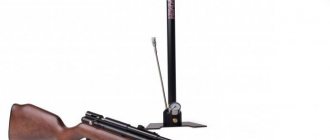
In my first publication, I want to tell you how I assembled a chronograph in a couple of evenings from cheap and accessible parts. As you probably already guessed from the name, this device is used to measure the speed of a bullet in air (and not so air) rifles and can be useful for monitoring its technical condition.
- Chinese Digispark - 80 rubles at the time of purchase
- Segment display on TM1637 - 90 rubles at the time of purchase
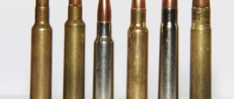
- IR LEDs and IR phototransistors (10 pairs) - 110 rubles at the time of purchase, we need 2 pairs
- Resistors 220 Ohm (100 pcs) - 70 rubles at the time of purchase, we only need 2 pieces
This ends the parts that need to be purchased. You don’t have to order resistors; similar values (but no less!) can be pulled out of unnecessary consumer electronics. Thus, the total costs are less than 350 rubles, which is nothing compared to the price of a new factory chronograph (over 1000 rubles for the simplest one, which in fact is even more primitive than our subject). In addition to the details, we will need:
- Wires - finding them offline for free is not a problem
- A piece of plastic water pipe more than 10cm long (diameter to suit your taste) - also easy to find
- Soldering accessories
- Multimeter (optional)
The first 3 parts are worthy of separate consideration, as they have their own characteristics, so let's start with mini-reviews of them.
1.1. Digispark
It is a simple miniature Arduino-compatible board with ATtiny85 on board. Read how to connect to the Arduino IDE on the official website of the project, where you can also find drivers for it. There are two main types of this board: with microUSB and a more brutal one with a USB connector located directly on the board.
My chronograph does not have its own power supply, so I chose the first board option. A built-in battery/rechargeable battery will greatly increase the price without adding virtually anything to usability. Almost everyone has a power bank and phone charging cable lying around.
Characteristics
naturally inherited from ATtiny85, its capabilities in our case are sufficient. In fact, the MK in the chronograph does nothing except interrogate two sensors and control the display. For those who are encountering Digispark for the first time, I have summarized the most important features in a table:
| Flash memory | 6Kb (2Kb occupied by bootloader) |
| RAM | 512 bytes |
| EEPROM | 512 bytes |
| Frequency | 16.5 MHz (default) |
| Number of I/O pins | 6 |
| Power to VIN | 5-12V |
| Pin 0 | PWM, SDA |
| Pin 1 | PWM |
| Pin 2 | SCK, ADC1 |
| Pin 3 | USB+, ADC3 |
| Pin 4 | PWM, USB-, ADC2 |
| Pin 5 | PWM, ADC0 |
I use this plate as a cheat sheet when developing various devices based on this board. As you may have noticed, the pin numbering for the analogRead() function is different, this should be taken into account. And one more feature: on the third pin there is a 1.5 kOhm pull-up resistor, because it is used in USB.
How to assemble a chronograph
Before answering the question, like how to make a frame chronograph for pneumatics with your own hands, you should prepare the case for installing sensors and microcircuit elements, which must be protected or located in places inaccessible to a bullet. It is recommended to paint the inside of the body with dark, non-glare paint that absorbs light. This will reduce the number of false alarms and increase the sensitivity of the device.
LEDs and photosensitive elements are installed in pre-prepared holes in the housing. The LEDs should protrude slightly into the internal cavity of the chronograph, and the photodetectors should be slightly recessed to reduce the intensity of incident external light.
Then install the board, connecting it to the sensors and preparing the power input points. If you want to create a microcircuit yourself, without involving third-party specialists, you can use the following scheme (Fig. 1).
Rice. 1 Chronograph chip
After assembling the main components, it is necessary to close the electrical circuit of the device, protecting it from mechanical stress and accidental ingress of moisture. The most convenient way to do this is to provide in advance a separate plastic box for the printed circuit board, which has outputs to the display, sensors and battery.
1.2. Display based on TM1637
The next important detail is the digital display on which information will be displayed. Any display can be used; my choice is due only to its low cost and ease of working with it. In principle, you can completely abandon the display and output data via cable to a PC, then the device will become even cheaper. To work you will need the DigitalTube library. The subject I linked to at the beginning of the post is a clone of the Grove display. Front view:
Behind:
The distance between the digits is the same, so when the colon is turned off, the numeric values are read normally. An example is supplied along with the standard library that works with Digispark without dancing with a tambourine:
All that the standard library can do is display the numbers 0-9 and the letters af, as well as change the brightness of the entire display.
The value of the digit is specified by the function display(int 0-3, int 0-15). A crash course in using the display
// 1. Declare a header file #include // 2. Set pins #define CLK 0 #define DIO 1 // 3. Declare a TM1637 object tm1637(CLK, DIO); // 4. Initialize void setup() { tm1637.init(); tm1637.set(6); // Brightness } // 5. Use void loop() { // Display number x int x = 1234; tm1637.display(0, x / 1000); tm1637.display(1, x / 100% 10); tm1637.display(2, x / 10 % 10); tm1637.display(3, x % 10); delay(500); } If you try to display a character with a code outside the boundaries of [0, 15], then the display shows nonsense, which is not static, so you won’t be able to cheat to display special characters (degrees, minus) without a tambourine:
This did not suit me, since in my chronograph I wanted to provide for the display of not only speed, but also the energy of the bullet (calculated based on the mass pre-written in the sketch), these two values should be displayed sequentially. To understand what the display is showing at a given time, you need to somehow separate these two values visually, for example, using the “J” symbol. Of course, you can stupidly use the colon symbol as a flag indicator, but this is not true and not kosher) Therefore, I went to understand the library and, based on the display function, made the setSegments(byte addr, byte data) function, which lights up the number with the number addr segments encoded in data:
void setSegments(byte addr, byte data) { tm1637.start(); tm1637.writeByte(ADDR_FIXED); tm1637.stop(); tm1637.start(); tm1637.writeByte(addr|0xc0); tm1637.writeByte(data); tm1637.stop(); tm1637.start(); tm1637.writeByte(tm1637.Cmd_DispCtrl); tm1637.stop(); } Segments are encoded extremely simply: the least significant bit of data is responsible for the uppermost segment, etc. clockwise, the seventh bit is responsible for the center segment. For example, the character '1' is encoded as 0b00000110. The eighth, most significant bit is used only in the second digit and is responsible for the colon; in all other digits it is ignored. To make my life easier, as any lazy IT specialist should, I automated the process of obtaining character codes using Excel:
Now you can easily do this:
Or like this:
Let's say HELLO
#include #define CLK 0 #define DIO 1 TM1637 tm1637(CLK, DIO); void setSegments(byte addr, byte data) { tm1637.start(); tm1637.writeByte(ADDR_FIXED); tm1637.stop(); tm1637.start(); tm1637.writeByte(addr|0xc0); tm1637.writeByte(data); tm1637.stop(); tm1637.start(); tm1637.writeByte(tm1637.Cmd_DispCtrl); tm1637.stop(); } void setup() { tm1637.init(); tm1637.set(6); } void loop() { // Output Hello setSegments(0, 118); setSegments(1, 121); setSegments(2, 54); setSegments(3, 63); delay(500); }
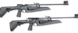
Types of chronographs for pneumatics
The following types of chronographs can be found on the shelves of gun stores:
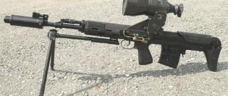
- Nadulny.
Cheap, compact and structurally simple device. Reliable fixation on the pneumatic barrel ensures high accuracy of readings. Can be used both indoors and outdoors. The lighting level does not affect the operation of the chronometer. Users of the device note its convenient transportation. Disadvantages - long preparation for speed measurements, the need to purchase a special adapter (a muzzle chronometer is often not suitable for a specific barrel). - Frame.
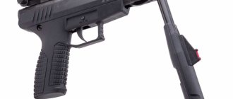
Universal, convenient, cheap chronometer. It will accurately measure the initial velocity, even when the weapon barrel is not close to the device. The disadvantage is that the readings are unstable in low light conditions. The advantage is an almost unlimited “frame”. - Horned.
Simplicity of design, ease of use, compatibility with all types of pneumatics – these are the advantages of this device. For correct readings, it is recommended to fix the weapon in one position. When shooting handheld, data errors are possible: the barrel changes position to the axis of the device. Another drawback is the limited “frame”, which can cause the chronometer to break.
1.3. Sensors
Here, unfortunately, I can’t say anything special, because on the product page there is not a word about the characteristics or at least a marking by which one could dig up a datasheet. Typical noname. Only the wavelength of 940 nm is known.
At the cost of one LED, I determined that a current of more than 40mA is fatal for them, and the supply voltage should be below 3.3V. The phototransistor is slightly transparent and reacts to light
The circuit is very simple and uncomplicated; of all the digispark pins, we only need P0, P1 for working with the display, and P2 for working with sensors:
As you can see, one resistor limits the current on the LEDs, the second pulls P2 to ground. The phototransistors are connected in series, so passing a bullet in front of any optocoupler causes the voltage across P2 to decrease. By recording two successive voltage surges and measuring the time between them, we can determine the speed of the bullet (knowing the distance between the sensors, of course). Using one pin for measurements has another advantage - there is no required direction of movement of the bullet, you can shoot from both ends. We will collect from this handful of parts:
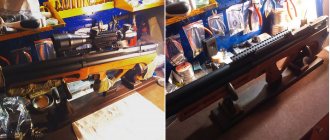
I followed the path of miniaturization and decided to make a sandwich using a piece of a breadboard:
The entire sandwich was filled with hot glue for strength:
All that remains is to place the sensors in the tube and solder the wires:
The photo shows that I placed an additional 100 mKF electrolyte in parallel with the LEDs, so that when powered by a power bank there would be no pulsation of the IR diodes.
Pin P2 was chosen as an input for a reason. Let me remind you that P3 and P4 are used in USB, so using P2 makes it possible to flash the device already assembled. Secondly, P2 is an analog input, so you can not use interrupts, but simply measure the difference in the cycle between the previous and current value on it; if the difference is above a certain threshold, then the bullet passes between one of the optocouplers. But there is one software trick, without which the above scheme will not take off, we will talk about it further.
Recommendations for owners of air guns
If the owner of an air gun is engaged in sports and recreational shooting, or has purchased a new, untuned weapon, a chronograph is necessary. An airsoft fan will need the device to control the NS, in order to avoid injury to players. However, it is important to note that induction samples only detect metal projectiles.
You don’t have to buy a measuring device if the device is not used regularly and has been targeted. If shooting performance deteriorates, it is enough to hand the pneumatic gun over to a gunsmith for maintenance.
Sensor chronographs operating in visible light are sensitive to light levels. It is better to use such devices indoors or outdoors in cloudy weather to obtain correct data. Some models with IR spectrum sensors work normally when exposed to glare.
Inflatable or framed - which is better?
Definitely the last one. The disadvantages of muzzle devices are that they often get shot and require the purchase of barrel attachments. You shouldn’t rely on the price tag – it’s better to pay extra. October 20, 2022
3.1. A few words about prescaler
Prescaler is a frequency divider, by default in arduino-like boards it is 128. The maximum sampling frequency of the ADC depends on the value of this value; by default, for a 16 MHz controller it turns out 16/128 = 125 kHz. Each digitization takes 13 operations, so the maximum pin sampling frequency is 9600 kHz (in theory, in practice no higher than 7 kHz). Those. the interval between measurements is approximately 120 µs, which is very, very long. A bullet flying at a speed of 300 m/s will fly 3.6 cm during this time - the controller simply will not have time to detect the fact that the bullet has passed through the optocoupler. For normal operation, you need an interval between measurements of at least 20 µs, the required divisor value for this is 16. I went even further and in my device I use a divider of 8, this is done as follows: #ifndef cbi #define cbi(sfr, bit) (_SFR_BYTE (sfr) &= ~_BV(bit)) #endif #ifndef sbi #define sbi(sfr, bit) (_SFR_BYTE(sfr) |= _BV(bit)) #endif void setup() { sbi(ADCSRA,ADPS2); cbi(ADCSRA,ADPS1); cbi(ADCSRA,ADPS0); ... } Real measurements of the analogRead interval on different dividers:
Required material and parts
Assembling a chronograph requires a number of devices and tools. Their complete list depends on the user’s skills in designing and installing electrical circuits.
The following components will be required:
- soldering iron, solder and flux - used at all stages of preparing the microcircuit and connecting wires;
- a microcircuit that is used to measure the time interval between the bullet passing the sensors and calculate speed parameters;
- LEDs – serve as a source of artificial lighting;
- optical receivers – record changes in illumination as a bullet passes between them and the LEDs;
- the body is rectangular in shape, has four sides and is hollow on the inside (like the outside of a matchbox). An all-metal body that is resistant to bullet impact if it misses is best;
- display for displaying measurement results.
3.2. Final sketch
I will not describe the code in detail, it is already well documented. Instead, I will describe in general terms the algorithm of its operation. So, all the logic comes down to the following steps:
- First cycle - the difference between the current and previous value on the pin is measured
- If the difference is greater than a given threshold, then we exit the loop and remember the current time (micros())
- Second cycle - similar to the previous one + time counter in the cycle
- If the counter has reached the specified value, then an error is reported and a transition to the beginning. This allows the cycle not to go into eternity if the bullet for some reason was not noticed by the second sensor
- If the counter has not overflowed and the difference in values is greater than the threshold, then measure the current time (micros())
- Based on the difference in time and distance between the sensors, we calculate the speed and display it on the screen
- Go to the beginning
This is a highly simplified model; in the code itself I added a whistle, including the calculation and display of bullet energy based on the bullet mass entered in advance in the code.
Actually, all the code
/* * Chronograph for measuring the speed of a bullet, © SinuX 03/23/2016 */ #include #define CLK 1 // Display pin #define DIO 0 // Display pin #define START_PIN 1 // Analog start pin #define END_PIN 1 // Analogue finish pin #define START_LEV 50 // Start trigger threshold #define END_LEV 50 // Finish trigger threshold #define TIMEOUT 10000 // Finish waiting time in microseconds #define BULLET_WEIGHT 0.00051 // Bullet weight in kilograms (to calculate energy) #define ENCODER_DIST 0.1 // Distance between sensors in meters (10cm = 0.1m) #define SHOW_DELAY 3000 // Time to display the result // To speed up analogRead #ifndef cbi #define cbi(sfr, bit) (_SFR_BYTE(sfr) &= ~_BV(bit )) #endif #ifndef sbi #define sbi(sfr, bit) (_SFR_BYTE(sfr) |= _BV(bit)) #endif // Service variables int prevVal, curVal;
unsigned long startTime, endTime; TM1637 tm1637(CLK, DIO); /* Reworked TM1637::display() function, which allows you to light individual segments * Segment numbering: low bit - high segment, etc. clockwise * Center segment is the most significant bit */ void setSegments(byte addr, byte data) { tm1637.start(); tm1637.writeByte(ADDR_FIXED); tm1637.stop(); tm1637.start(); tm1637.writeByte(addr|0xc0); tm1637.writeByte(data); tm1637.stop(); tm1637.start(); tm1637.writeByte(tm1637.Cmd_DispCtrl); tm1637.stop(); } // Initialization void setup() { // Set prescaler to 8 to speed up analogRead cbi(ADCSRA,ADPS2); sbi(ADCSRA,ADPS1); sbi(ADCSRA,ADPS0); // Initialize the display tm1637.init(); tm1637.set(6); // Display the greeting setSegments(0, 118); setSegments(1, 121); setSegments(2, 54); setSegments(3, 63); delay(1000); } // Main loop void loop() { // Waiting screen showReady(); // Waiting for start curVal = analogRead(START_PIN); do { prevVal = curVal; curVal = analogRead(START_PIN); } while (curVal - prevVal < START_LEV); startTime = micros(); // Waiting for finish curVal = analogRead(END_PIN); do { prevVal = curVal; curVal = analogRead(END_PIN); // If the waiting interval is exceeded, show an error and exit the loop if (micros() - startTime >= TIMEOUT) { showError(); return; } } while (curVal - prevVal < END_LEV); endTime = micros(); // Calculate and display the result showResult(); } // Display the shot waiting screen void showReady() { setSegments(0, 73); setSegments(1, 73); setSegments(2, 73); setSegments(3, 73); delay(100); } // Calculation and display of bullet speed, energy void showResult() { // Calculation of bullet speed in m/s and display float bulletSpeed = ENCODER_DIST * 1000000 / (endTime - startTime); tm1637.display(0, (int)bulletSpeed / 100% 10); tm1637.display(1, (int)bulletSpeed / 10% 10); tm1637.display(2, (int)bulletSpeed % 10); setSegments(3, 84); delay(SHOW_DELAY); // Calculate energy in joules and display float bulletEnergy = BULLET_WEIGHT * bulletSpeed * bulletSpeed / 2; tm1637.point(1); // Instead of a dot ':' - a crutch, but it will do) tm1637.display(0, (int)bulletEnergy / 10% 10); tm1637.display(1, (int)bulletEnergy % 10); tm1637.display(2, (int)(bulletEnergy * 10) % 10); setSegments(3, 30); delay(SHOW_DELAY); tm1637.point(0); } // Display an error when the bullet timeout is exceeded void showError() { setSegments(0, 121); setSegments(1, 80); setSegments(2, 80); setSegments(3, 0); delay(SHOW_DELAY); } When connected correctly, the device took off almost immediately, the only flaw discovered was that it reacts negatively to LED and fluorescent lighting (pulsation frequency is about 40 kHz), hence spontaneous errors can appear.
In total, the device has 3 operating modes: Greeting after switching on and switching to shot standby mode (the screen is filled with stripes):
In case of an error, “Err” is displayed, and again goes to standby mode:
Well, I measured the speed myself:
After a shot, the bullet's speed is first shown (with the symbol 'n'), then the energy (symbol 'J'), and the energy is calculated with an accuracy of one decimal place (in the gif you can see that when joules are shown, the colon is lit). I couldn’t find a prettier case yet, so I just filled everything with thermal nozzles:
I guess that's all for me, I hope it was useful to someone.
Criterias of choice
Only 2 criteria are important when choosing the optimal device:
- Accuracy of readings.
The buyer should pay attention to the percentage of deviations in the speed measurement process. The speed corridor can be lowered: the minimum and maximum values are sufficient (with a margin) to perform a test of an air gun. The main thing is the lower speed threshold. - Data output tool.
It is at the discretion of the buyer how he is comfortable receiving information and then using it.
A secondary criterion is the price of the device. Here the reference point is the financial capabilities of the pneumatic user.
The principle of operation of a homemade chronograph
The device can be powered from batteries, a battery or a power supply (from the mains). Autonomous operation is most convenient, since weapon adjustment cannot always be done at home.
Speed measurement is carried out in several stages:
- when crossing the axis of the first sensor, the microprocessor time count is reset to zero;
- after passing the optical axis of the second sensor, the timing stops and is transferred for calculation;
- The bullet speed calculated by the microprocessor is displayed on the display.
Diagram of the frame chronograph operation
Making a frame chronograph for pneumatics with your own hands from scratch requires soldering experience, basic knowledge in electrical engineering and electrical circuit design. To simplify the task, the layout of the microcircuit can be ordered from radio amateurs, providing them with the parts necessary for the work. A self-assembled chronograph is an excellent investment and saves money, which can be spent on tuning pneumatics or purchasing a long-awaited body kit.
The video shows a test of a homemade frame chronograph: