It is noteworthy that air rifles are available for free sale in specialized stores, and therefore, in order to become the owner of a “pneumatic gun”, you can do without a specific registration procedure.
This explains why beginners are interested in the question of how the “air” works. The fact is that wind rifle units have different designs and purposes. Some samples are suitable as toys, but there are also products that are purchased for training and hunting.
Trunk
6. The barrel
(Fig. 2) serves to direct the flight of the bullet.
Inside it has a channel
with four grooves that curl from left to top to right.
The rifling
serves to impart rotational movement to the bullet during flight;
the spaces between the cuts are called margins
;
the distance between two opposite fields (in diameter) determines the caliber
of the bore; it is equal to 7.62 mm.
Rice. 2. Barrel with receiver:
1 — sight; 2 - front sight
The back of the canal is smooth; it serves to house the cartridge and is called the chamber
.
The chamber is connected to the rifled part of the bore via a bullet entry
.
Outside, on the muzzle, the barrel has the base of the front sight. An aiming block is mounted on the rear of the barrel
and stamped (above the chamber) the number, mark and year of manufacture of the rifle.
The thickened breech of the barrel ends with a stump
having an external thread.
The receiver is screwed tightly onto the stump of the barrel
;
on the edge there is a hemp - a bevel
along which the ejector hook slides when the bolt is turned.
The carbine mod. 1944, a fixed tube is placed on the muzzle of the barrel and tightly fixed, serving as the base of the bayonet (see Fig. 27). At the top of the front end of the tube is the base of the front sight. At the rear end of the tube on the right there is a boss with lugs to strengthen the bayonet. In the eyes there are holes for the fastening screw, which is the axis of rotation of the bayonet when tilting and folding it.
The lugs at the ends have beveled projections: the lower ones are for securing the movable bayonet tube in the stowed (folded) position of the bayonet, the upper ones are for lifting the bayonet tube when the bayonet is folded into the firing position.
Purpose
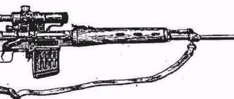
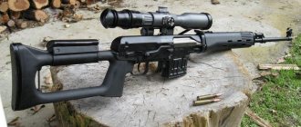
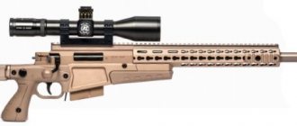
The 7.62 mm Dragunov sniper rifle is a sniper weapon and is designed to destroy various emerging, moving, open and camouflaged single targets.
The rifle is equipped with a PSO-1 sniper scope. The optical sight allows you to target infrared sources at night, as well as under unfavorable lighting conditions, when it is difficult to shoot at targets with an open sight.
When observing infrared sources, the infrared rays emitted by the source pass through the scope lens and affect the screen located in the focal plane of the lens. At the location of the infrared rays, a glow appears on the screen, giving a visible image of the source in the form of a round green color.
For shooting from a sniper rifle, rifle cartridges with ordinary, tracer and armor-piercing incendiary bullets or rifle sniper cartridges are used.
Fire from a sniper rifle is carried out in single shots.
When firing, cartridges are supplied from a box magazine with a capacity of 10 rounds.
Receiver
7. Receiver
(Fig. 3) serves to place the shutter. Attached to it are: a cut-off reflector, a magazine box with a feed mechanism and a trigger mechanism.
Rice. 3. Receiver:
1 - tail; 2 — upper window; 3 — grooves for the clip; 4 - stop
Outside the receiver has:
a) top window
for inserting cartridges and placing the bolt comb; the window has two bevels: the front one makes it easier to open the shutter; the rear part of the ridge of the bolt stem slides along the rear; at the beginning it turned to the right when closing;
b) grooves
for inserting a clip of cartridges: one on the right side and two on the left, of which the front one is for the side of the clip;
c) upper groove
to direct the movement of the ridges of the bolt stem and trigger;
d) tail
with a hole for the tail rotor and a recess for moving the button and cocking the hammer when setting it to the safety cock;
e) emphasis
for fastening to the stock; in the stop there is a threaded socket for the stop screw;
e) bottom window
for the passage of cartridges from the receiver to the magazine and back;
g) threaded hole
for the trigger spring screw;
h) ears
for the trigger axis;
i) gap
for a trigger mechanism with shoulders to rest the trigger when moving the bolt;
j) gap
for the cut-off reflector blade;
l) groove
for the heel of the reflector cut-off with a threaded hole for its screw.
Inside the receiver has:
a) channel
for placing the shutter;
b) threaded shoulder
, with which the receiver is screwed onto the barrel stump;
c) two longitudinal and one annular grooves
, in which the combat lugs of the combat cylinder move when chambering and turning the bolt;
d) grooves
for the passage of the ejector when chambering and turning the bolt;
e) bevels
for directing cartridges fed from the magazine box into the chamber;
e) protrusion
on the right side, which, together with the reflector cut-off, keeps the cartridge fed from the magazine box into the receiver from jumping up;
g) bottom groove
for directing the movement of the connecting bar and for the passage of the combat protrusion of the combat cylinder;
h) removal
on the right side (under the groove for inserting the clip) for the passage of the edges of the cartridge cases when loading from the clip.
Possible delays and malfunctions that occur during shooting and ways to eliminate them
The delay that occurs during shooting should be eliminated by reloading, to do this, vigorously pull the bolt frame back by the handle, release it and continue shooting. If the delay is not resolved, then you need to find out the reason for its occurrence and eliminate the delay as indicated below.
Delay and their characteristics
Failure to feed cartridge. The bolt is in the forward position, but the shot did not occur - there is no cartridge in the chamber.
Stuck cartridge. The cartridge hit the breech end of the barrel with a bullet, the moving parts remained in the middle position.
Reasons for delay
1. Contamination or malfunction of the magazine.
2. Malfunction of the magazine latch.
3. Curvature of the bends of the side walls of the magazine.
Remedies
Reload the rifle and continue shooting. If the delay recurs, replace the magazine. If the magazine latch is faulty, send the rifle to a repair shop.
While holding the reloading handle, remove the stuck cartridge and continue shooting. If the delay recurs, replace the magazine.
| Delay and their characteristics | Reasons for delay | Remedies |
| Misfire. The bolt is in the forward position, the cartridge is in the chamber, the trigger is pulled - there is no shot. | I. Chuck malfunction. 2. Malfunction of the firing pin or firing mechanism; contamination or hardening of the lubricant. | Reload the rifle and continue shooting. When the delay is repeated, inspect and clean the firing pin and trigger mechanism; If they break or wear out, send the rifle to a workshop. |
| Failure to remove the cartridge case. The cartridge case is in the chamber, the next cartridge has buried a bullet in it, the moving parts have stopped in the middle position. | 1. Dirty cartridge or contaminated chamber. 2. Contamination or malfunction of the ejector or its spring. | Pull the reloading handle back and, holding it in the rear position, separate the magazine and remove the buried cartridge. Using a bolt or cleaning rod, remove the cartridge case from the chamber. Continue shooting. If the delay repeats, clean the chamber. Inspect and clean the ejector from dirt and continue shooting. If the ejector malfunctions, send the rifle to a repair shop. |
| Sticking or not reflecting the sleeve. The cartridge case was not thrown out of the receiver, but remained in it in front of the bolt or was sent back into the chamber by the bolt. | 1. Contamination of rubbing parts, gas paths or chamber. 2. The ejector is dirty or malfunctioning. | Pull the charging handle back, eject the cartridge case and continue shooting. If the delay repeats, clean the gas paths, rubbing parts and the chamber; Lubricate rubbing parts. If the ejector malfunctions, send the rifle to a repair shop. |
Cut-off reflector
8. Cut-off reflector
serves to separate cartridges fed from the magazine box into the receiver, and to reflect cartridges (cartridges) removed from the chamber by the ejector.
Rice. 4. New sample cut-off reflector:
a - 1 - cut-off; 2 - reflector; b - 1 - protrusions (stops); 2 - reflective protrusion; 3 - connecting protrusion; 4 - recess; c — 1 — heel; 2 - hole for screw; 3 - rectangular hole; 4 - cutting tooth; 5 - spring part
Cut-off reflector of a new sample (Fig. 4). consists of a cutoff
with a cutting tooth and heel and
a reflector
with a reflective protrusion. The cutoff and the reflector are connected to each other using a connecting protrusion located on the reflector and inserted into the corresponding hole on the cutoff.
The old-style reflector cut-off (Fig. 5) is one whole part. It has a blade with a reflective protrusion and a cutting tooth and a spring part
with heel.
The cutoff (spring part) with its heel is placed in the groove of the receiver and secured in it with a screw.
The reflector (blade) is placed in the slots of the receiver. When the bolt is open, it comes out of the slot into the receiver channel and, together with its protrusion, holds the upper (next) cartridge in the receiver channel. The reflective protrusion is placed in the longitudinal groove of the bolt, and when the bolt is retracted back, it passes through the longitudinal groove of the combat cylinder and reflects the cartridge case (cartridge) removed from the chamber by the combat cylinder. The cutting tooth is placed in a cutout in the left wall of the magazine box; when the shutter is open, it goes inside the box and, resting against the sleeve of the cartridge following the next one, cuts off (holds) the cartridges in the magazine box. On the reflector (blade) behind the reflective protrusion there is a recess for the cartridge head to pass through when lowering cartridges from the clip into the magazine box.
Rice. 5. Old-style reflector cut-off:
1 - blade; 2 - reflective protrusion; 3 - spring part; 4 - cutting tooth; 5 - heel
Trigger
9. Trigger
(Fig. 6) consists of a trigger, trigger spring, screw and axle.
Trigger
serves to retract the sear of the trigger spring when the trigger is released from cocking.
He has: a tail
for placing a finger when pulling the trigger,
a slot
for the passage of the trigger spring,
a hole
for the axis and
a bolt stop
, which, entering the lower groove of the connecting bar and resting against its front wall, stops the bolt when it is moved back.
Trigger spring
has:
a sear
to hold the hammer cocked and
a heel with a hole
for a screw attaching the spring to the receiver.
Trigger axis
passes through holes in the trigger and receiver lugs.
Rice. 6. Trigger:
1 — trigger; 2 — trigger spring; 3 — trigger spring screw; 4 - axis
Dispensers
This type of equipment is used on weapons with pre-pumping or gas cartridges. Its task is to release a limited amount of gas into the barrel at the time of cocking or firing, depending on the design.
Gas cylinder systems
In most gas-operated guns, the dispensers look and operate the same. To ensure proper functioning, the dispenser has three different openings. The first of them is intended for installing a can and is equipped with a special sealing gasket and a needle for piercing the membrane.
After the canister takes its place and is punctured, the gas enters a special chamber, behind which the release valve is located. Due to the high pressure, the valve does not allow gas to pass through until the release occurs. When the trigger is pulled, the trigger hits the stem, causing the valve to open. It returns to its place under the action of a spring and pressure.
The stronger the spring, the stronger the shock, and the longer the valve will remain open. Therefore, the spring itself and the stiffness of the valve can be considered the main metering devices of a pistol with gas cylinder equipment.
There are systems that do not have a third hole for the rod. In this case, the descent occurs due to the impact of the barrel itself with a weight on the exhaust valve.
Pre-pumped systems
Since the pressure in such a weapon can vary from shot to shot, it has two additional features. The first is a built-in reducer that controls the pressure directly in the dispenser chamber. Due to this, it is possible to maintain approximately the same power over several shots.
When the number of atmospheres in the container begins to decrease, the valve no longer fits so tightly, which can lead to a smooth release of air. To prevent this, additional pressure of the valve to the gasket is provided using a spring.
Sight and front sight
10. Aim
(Fig. 7) serves to direct the rifle at the target and to give it the appropriate aiming angles when shooting at various distances. It consists of an aiming block, an aiming bar with a clamp and a spring.
Aiming block
has two posts with beveled ribs. At the front end of the block there are ears with holes for the sighting bar pin; at the rear end there is a groove to strengthen the sighting bar spring.
Rice. 7. Sight:
1 — aiming block; 2 — sighting bar; 3 - clamp
Rice. 8. Sighting bar with clamp
Sighting bar
(Fig. is reinforced with a pin in the ears of the aiming block and can rotate on the pin. At the rear end of the bar there is
a mane
with a slot for aiming.
On the outer side of the bar there are divisions with numbers from 1 to 20, indicating distances in hundreds of meters, on the right side - even and on the left - odd; Between the divisions there are small lines for setting the sight with an accuracy of up to 50 m.
On the side edges of the strap there are cutouts for the latches of the sighting clamp.
Sighting clamp
placed on the sighting bar and held in position by latches. Each latch has a spring and a tooth, with which it slides into a cutout on the side edge of the sighting bar (Fig. 9).
Rice. 9. Aiming clamp latch:
1 - head protrusion; 2 - cylindrical socket; 3 - latch spring; 4 - latch; 5 - socket; 6 - tooth; 7 - cutout
Sighting bar spring
the rear end is fixed in the groove of the sighting block, and the front end rests against the heel of the sighting bar and thereby holds the bar in its given position.
11. Front sight
(Fig. 10) serves for aiming. It is fixed in the hole of the ring front sight, which is pushed with a protrusion into the groove of the base of the front sight on the barrel (for a carbine model 1944 - on a fixed barrel tube). On the front plane of the front sight there is a mark that coincides with the mark on the base of the front sight, and there are recesses for punching.
Rice. 10. Front sight with a muzzle:
1 - front sight; 2 - namushnik
Rice. 11. Front sight of a rifle from previous years of manufacture (with a muzzle on a bayonet)
Note. In rifles of previous years of manufacture, the front sight with its claws is directly pushed into the groove of the front sight base and secured with a core (Fig. 11).
Gate
12. Gate
(Fig. 12) serves to chamber the cartridge, lock the barrel bore, fire a shot and remove the cartridge case (cartridge) from the chamber. The bolt consists of: a bolt stem, a combat cylinder, an ejector, a trigger, a firing pin, a mainspring and a connecting strip.
Rice. 12. Shutter:
1 — shutter stem; 2 - combat larva; 3 — connecting strip; 4 - trigger
13. Bolt
(Fig. 13) has:
a) comb
to direct the movement of the bolt in the receiver channel; the ends of the comb have bevels that slide along the corresponding bevels of the upper receiver window: the front one when opening, and the rear one when closing the bolt;
b) handle
for shutter action;
c) nest
for the nipple of the combat larva;
d) groove
for the ridge of the connecting strip post;
e) beveled groove
for the movement of the reflective protrusion of the cutoff-reflector during longitudinal movements of the shutter and for moving it to the left when closing the shutter;
e) notch
on the rear section of the bolt stem, into which the nipple of the screw protrusion of the trigger enters and this keeps the trigger from turning when the bolt is pulled back;
g) screw cutout
, by which, when the shutter is opened, the hammer and firing pin are pulled back and cocked;
h) removal
for the movement of the trigger safety lug;
Rice. 13. Rifle bolt stem mod. 1891/80:
1 - ridge; 2 — handle; 3 — groove for the ridge of the connecting strip post; 4 - screw cutout
i) small recess
to hold the trigger on the safety cock;
j) channel
two diameters: a larger one to accommodate the mainspring and connecting bar tube and a smaller one to accommodate the passage of the firing pin. The end of the mainspring, placed on the firing pin, rests against the resulting ledge.
Note. On a sniper rifle, the bolt handle is elongated and curved for ease of operation when an optical sight is installed (Fig. 14).
Rice. 14. Sniper rifle bolt stem
Rice. 15. Combat larva:
1 - nipple; 2 — combat ledges
14. Combat larva
(Fig. 15) serves to lock the barrel bore. She has:
a) a cup with a whisk
for placing the cartridge cap;
b) two combat ledges
, which, when the bolt is closed, are adjacent with their rear edges to the walls of the annular groove of the receiver and withstand the pressure of the powder gases on the bolt when fired;
c) nipple
for connecting the combat cylinder with the bolt stem; it fits into the socket of the bolt stem, due to which the combat larva rotates along with the stem;
d) groove
for nipple connecting bar;
e) groove
for the passage of the cutoff-reflector during longitudinal movements of the shutter, as well as for the passage of the nipple of the connecting strip;
e) groove
for placing the ejector; it has a socket for the ejector heel;
g) channel
two diameters: the smaller one for the firing pin, the larger one for the front end of the connecting bar tube.
15. Ejector
(Fig. 16) is used to remove cartridges (cartridges) from the chamber and to throw them out of the receiver using the reflective protrusion of the cutoff-reflector.
It has a hook
, which grabs the cartridge case by its edge, and
a heel
to strengthen the ejector in the groove of the combat cylinder.
Rice. 16. Ejector:
1 - hook; 2 - heel
Rice. 17. Trigger:
1 - ridge; 2 - combat platoon; 3 - button
16. Trigger
(Fig. 17) serves to place the drummer in combat and safety platoons. He has:
a) comb
to direct the movement of the trigger in the upper groove of the receiver;
b) safety ledge
(under the hammer ridge) to set the hammer to safety cock;
c) screw protrusion
to pull the trigger back when opening the shutter; the protrusion has a nipple to keep the trigger from turning when the bolt is pulled back;
d) combat platoon
with grooves for the connecting strip fork; the sear of the trigger spring jumps over its front edge when the bolt is closed or the trigger is pulled back;
d) a button
for setting the hammer to combat (without opening the bolt) and safety cocks; the button has a notch for gripping with fingers, and on the back surface there are lines for installing a striker slot along them;
e) channel
, in the front part it is smooth, and in the rear part it is threaded, for screwing the striker into it.
17. Drummer
(Fig. 18) has
a firing pin
for breaking the cartridge primer and
a rim
for resting the mainspring.
The rim divides the firing pin into two parts: the front (short) blade
and the rear (long)
rod
with a threaded end for screwing on the trigger.
a slot
on the cut of the rod to check the correct connection of the firing pin to the trigger.
Rice. 18. Drummer:
1 - rod; 2 - corolla; 3 - blade; 4 - striker
18. Action spring
(Fig. 19) imparts to the striker the rapid movement necessary to forcefully strike the primer with the firing pin. It is put on the striker rod.
Rice. 19. Mainspring
19. Connecting strip
(Fig. 20) connects the combat cylinder to the bolt stem and holds the bolt in the receiver when it is pulled back. She has:
a) nipple
, which fits into the groove of the combat cylinder and connects it to the connecting bar;
Rice. 20. Connecting strip:
1 - stand; 2 - nipple; 3 - fork
b) stand
with comb and tube;
the front part of the tube enters the channel
of the combat cylinder, and the rear part enters the channel of the bolt stem;
inside the tube there is a channel for the passage of the striker; the rear part of the channel is oval, in the shape of the striker blade, to eliminate its rotation; the ridge
of the rack fits into the groove of the bolt stem and connects the connecting strip to it;
on the left side of the rack there is a groove
for the passage of the cut-off reflector during longitudinal movements of the shutter;
c) fork
, into which the cocking cock enters with its grooves;
d) groove
(on the lower surface of the connecting strip) for the movement of the bolt stop, which, resting against the front wall of this groove, keeps the bolt pulled back from falling out of the receiver channel;
d) bevel
(on the upper surface of the bar, on the left) for the cut-off blade-reflector.
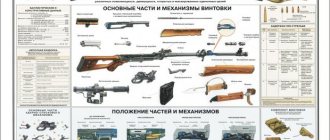
Chapter I RIFLE CONSTRUCTION
Chapter I
RIFLE CONSTRUCTION
DESCRIPTION OF RIFLE PARTS
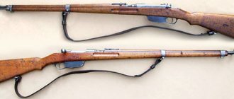
Trunk
6. The barrel (Fig. 2) serves to direct the flight of the bullet. Inside it has a channel with four grooves that curl from left to top to right. The rifling serves to impart rotational movement to the bullet during flight; the spaces between the cuts are called margins; the distance between two opposite fields (in diameter) determines the caliber of the bore; it is equal to 7.62 mm.
Rice. 2.
Barrel with receiver:
1
— sight;
2
- front sight
The back of the canal is smooth; it serves to house the cartridge and is called the chamber . The chamber is connected to the rifled part of the bore through a bullet entrance.
Outside, on the muzzle, the barrel has the base of the front sight. On the back of the barrel there is a sighting block and the number, stamp and year of manufacture of the rifle are stamped (above the chamber).
The thickened breech of the barrel ends in a stump with an external thread. The receiver is screwed tightly onto the stump of the barrel; on the edge there is a hemp - a bevel along which the ejector hook slides when the bolt is turned.
The carbine mod. 1944, a fixed tube is placed on the muzzle of the barrel and tightly fixed, serving as the base of the bayonet (see Fig. 27). At the top of the front end of the tube is the base of the front sight. At the rear end of the tube on the right there is a boss with lugs to strengthen the bayonet. In the eyes there are holes for the fastening screw, which is the axis of rotation of the bayonet when tilting and folding it.
The lugs at the ends have beveled projections: the lower ones are for securing the movable bayonet tube in the stowed (folded) position of the bayonet, the upper ones are for lifting the bayonet tube when the bayonet is folded into the firing position.
Receiver
7. The receiver (Fig. 3) is used to house the bolt. Attached to it are: a cut-off reflector, a magazine box with a feed mechanism and a trigger mechanism.
Rice. 3.
Receiver:
1
- tail;
2
— upper window;
3
— grooves for the clip;
4
- stop
Outside the receiver has:
a) an upper window for inserting cartridges and placing the bolt ridge; the window has two bevels: the front one makes it easier to open the shutter; the rear part of the ridge of the bolt stem slides along the rear; at the beginning it turned to the right when closing;
b) grooves for inserting a clip with cartridges: one on the right side and two on the left, of which the front one is for the side of the clip;
c) an upper groove for directing the movement of the ridges of the bolt stem and trigger;
d) a tail with a hole for the tail rotor and a recess for moving the button and cocking the hammer when setting it to the safety cock;
e) stop for fastening to the stock; in the stop there is a threaded socket for the stop screw;
f) lower window for the passage of cartridges from the receiver to the magazine and back;
g) threaded hole for the trigger spring screw;
h) lugs for the trigger axis;
i) a slot for the trigger mechanism with shoulders to rest the trigger when retracting the bolt;
j) a slot for the cut-off reflector blade;
l) a groove for the heel of the cut-off reflector with a threaded hole for its screw.
Inside the receiver has:
a) a channel for placing the shutter;
b) a rifled ledge with which the receiver is screwed onto the barrel stump;
c) two longitudinal and one annular grooves in which the combat lugs of the combat cylinder move when chambering and turning the bolt;
d) grooves for the passage of the ejector when chambering and turning the bolt;
e) bevels for directing cartridges fed from the magazine box into the chamber;
f) a protrusion on the right side, which, together with the cut-off reflector, keeps the cartridge fed from the magazine box into the receiver from jumping up;
g) a lower groove for directing the movement of the connecting bar and for the passage of the combat protrusion of the combat cylinder;
h) a recess on the right side (under the groove for inserting the clip) for the passage of the edges of the cartridge cases when loading from the clip.
Cut-off reflector
8. The reflector cut-off serves to separate the cartridges fed from the magazine box into the receiver, and to reflect the cartridges (cartridges) removed from the chamber by the ejector.
Rice. 4.
New sample reflector cut-off:
a - 1
— cutoff;
2
- reflector;
b - 1
- protrusions (stops);
2
- reflective protrusion;
3
- connecting protrusion;
4
- recess;
c — 1
— heel;
2
- hole for screw;
3
- rectangular hole;
4
- cutting tooth;
5
- spring part
Cut-off reflector of a new sample (Fig. 4). consists of a cut-off with a cutting tooth and a heel and a reflector with a reflective protrusion. The cutoff and the reflector are connected to each other using a connecting protrusion located on the reflector and inserted into the corresponding hole on the cutoff.
The old-style reflector cut-off (Fig. 5) is one whole part. It has a blade with a reflective protrusion and a cutting tooth and a spring part with a heel.
The cutoff (spring part) with its heel is placed in the groove of the receiver and secured in it with a screw.
The reflector (blade) is placed in the slots of the receiver. When the bolt is open, it comes out of the slot into the receiver channel and, together with its protrusion, holds the upper (next) cartridge in the receiver channel. The reflective protrusion is placed in the longitudinal groove of the bolt, and when the bolt is retracted back, it passes through the longitudinal groove of the combat cylinder and reflects the cartridge case (cartridge) removed from the chamber by the combat cylinder. The cutting tooth is placed in a cutout in the left wall of the magazine box; when the shutter is open, it goes inside the box and, resting against the sleeve of the cartridge following the next one, cuts off (holds) the cartridges in the magazine box. On the reflector (blade) behind the reflective protrusion there is a recess for the cartridge head to pass through when lowering cartridges from the clip into the magazine box.
Rice. 5.
Old-style reflector cut-off:
1
- blade;
2
- reflective protrusion;
3
- spring part;
4
- cutting tooth;
5
- heel
Trigger
9. The trigger mechanism (Fig. 6) consists of a trigger, trigger spring, screw and axle.
The trigger serves to retract the sear of the trigger spring when the hammer is released from cocking.
It has: a tail for placing a finger when releasing the trigger, a slot for the passage of the trigger spring, a hole for the axis and a bolt stop , which, entering the lower groove of the connecting bar and resting against its front wall, stops the bolt when it is moved back.
The trigger spring has: a sear to hold the hammer cocked and a heel with a hole for the screw that attaches the spring to the receiver.
The trigger axis passes through the holes in the trigger and receiver lugs.
Rice. 6.
Trigger:
1
- trigger;
2
— trigger spring;
3
— trigger spring screw;
4
- axis
Sight and front sight
10. The sight (Fig. 7) serves to direct the rifle at the target and to give it the appropriate aiming angles when shooting at various distances. It consists of an aiming block, an aiming bar with a clamp and a spring.
The sighting block has two posts with beveled ribs. At the front end of the block there are ears with holes for the sighting bar pin; at the rear end there is a groove to strengthen the sighting bar spring.
Rice. 7.
Aim:
1
- sighting block;
2
— sighting bar;
3
- clamp
Rice. 8.
Sighting bar with clamp
The aiming bar (Fig. is reinforced with a pin in the ears of the aiming block and can rotate on the pin. At the rear end of the bar there is a mane with a slot for aiming.
On the outer side of the bar there are divisions with numbers from 1 to 20, indicating distances in hundreds of meters, on the right side - even and on the left - odd; Between the divisions there are small lines for setting the sight with an accuracy of up to 50 m.
On the side edges of the strap there are cutouts for the latches of the sighting clamp.
The sighting collar is put on the sighting bar and is held in position by latches. Each latch has a spring and a tooth, with which it slides into a cutout on the side edge of the sighting bar (Fig. 9).
Rice. 9.
Aiming clamp latch:
1
- head protrusion;
2
- cylindrical socket;
3
- latch spring;
4
- latch;
5
- socket;
6
- tooth;
7
- cutout
The rear end of the sighting bar spring is fixed in the groove of the sighting block, and the front end rests against the heel of the sighting bar and thereby holds the bar in its given position.
11. The front sight (Fig. 10) is used for aiming. It is fixed in the hole of the ring front sight, which is pushed with a protrusion into the groove of the base of the front sight on the barrel (for a carbine model 1944 - on a fixed barrel tube). On the front plane of the front sight there is a mark that coincides with the mark on the base of the front sight, and there are recesses for punching.
Rice. 10.
Front sight with a namushnik:
1
- front sight;
2
- namushnik
Rice. eleven.
Front sight of a rifle from previous years of manufacture (with a muzzle on a bayonet)
Note
. In rifles of previous years of manufacture, the front sight with its claws is directly pushed into the groove of the front sight base and secured with a core (Fig. 11).
Gate
12. The bolt (Fig. 12) is used to send the cartridge into the chamber, lock the barrel bore, fire a shot and remove the cartridge case (cartridge) from the chamber. The bolt consists of: a bolt stem, a combat cylinder, an ejector, a trigger, a firing pin, a mainspring and a connecting strip.
Rice. 12.
Gate:
1
- shutter stem;
2
- combat larva;
3
— connecting strip;
4
- trigger
13. The stem of the shutter (Fig. 13) has:
a) a ridge to direct the movement of the bolt in the receiver channel; the ends of the comb have bevels that slide along the corresponding bevels of the upper receiver window: the front one when opening, and the rear one when closing the bolt;
b) a handle for operating the bolt;
c) nest for the nipple of the fighting larva;
d) groove for the ridge of the connecting strip post;
e) a beveled groove for moving the reflective protrusion of the cutoff-reflector during longitudinal movements of the shutter and for moving it to the left when closing the shutter;
e) a recess on the rear cut of the bolt stem, into which the nipple of the screw protrusion of the trigger fits and this keeps the trigger from turning when the bolt is pulled back;
g) a screw cutout, with which, when the bolt is opened, the trigger with the firing pin is pulled back and cocked;
h) a recess for the movement of the safety protrusion of the trigger;
Rice. 13.
Rifle bolt stem mod. 1891/80:
1
- comb;
2
— handle;
3
— groove for the ridge of the connecting strip post;
4
- screw cutout
i) a small recess to hold the hammer on the safety cock;
j) a channel of two diameters: a larger one for housing the mainspring and connecting bar tube and a smaller one for the passage of the firing pin. The end of the mainspring, placed on the firing pin, rests against the resulting ledge.
Note
. On a sniper rifle, the bolt handle is elongated and curved for ease of operation when an optical sight is installed (Fig. 14).
Rice. 14.
Sniper rifle bolt stem
Rice. 15.
Combat larva:
1
- nipple;
2
— combat ledges
14. The combat larva (Fig. 15) serves to lock the barrel bore. She has:
a) a cup with a rim for placing the cartridge cap;
b) two lugs, which, when the bolt is closed, are adjacent with their rear edges to the walls of the annular groove of the receiver and withstand the pressure of the powder gases on the bolt when fired;
c) a nipple for connecting the combat larva with the bolt stem; it fits into the socket of the bolt stem, due to which the combat larva rotates along with the stem;
d) groove for the nipple of the connecting strip;
e) a groove for the passage of the cutoff-reflector during longitudinal movements of the shutter, as well as for the passage of the nipple of the connecting strip;
f) a groove for placing the ejector; it has a socket for the ejector heel;
g) a channel of two diameters: a smaller one for the firing pin, a larger one for the front end of the connecting bar tube.
15. The ejector (Fig. 16) is used to remove cartridges (cartridges) from the chamber and to eject them from the receiver using the reflective protrusion of the cutoff-reflector. It has a hook , which grabs the cartridge case by its edge, and a heel to strengthen the ejector in the groove of the combat cylinder.
Rice. 16.
Ejector:
1
- hook;
2
- heel
Rice. 17.
Trigger:
1
- comb;
2
- combat platoon;
3
- button
16. The trigger (Fig. 17) is used to place the firing pin on the combat and safety cocks. He has:
a) a comb to direct the movement of the trigger in the upper groove of the receiver;
b) a safety protrusion (under the hammer ridge) for setting the hammer to safety cock;
c) a screw protrusion for retracting the trigger back when opening the bolt; the protrusion has a nipple to keep the trigger from turning when the bolt is pulled back;
d) combat cocking with grooves for the fork of the connecting strip; the sear of the trigger spring jumps over its front edge when the bolt is closed or the trigger is pulled back;
e) a button for setting the hammer to action (without opening the bolt) and safety cock; the button has a notch for gripping with fingers, and on the back surface there are lines for installing a striker slot along them;
e) a channel, smooth in the front part, and threaded in the rear, for screwing the striker into it.
17. The firing pin (Fig. 18) has a firing pin for breaking the cartridge primer and a rim for resting the mainspring. The rim divides the firing pin into two parts: the front (short) blade and the rear (long) rod with a threaded end for screwing on the trigger. a slot on the cut of the rod to check the correct connection of the firing pin to the trigger.
Rice. 18.
Drummer:
1
- rod;
2
- corolla;
3
- blade;
4
- striker
18. The mainspring (Fig. 19) imparts to the firing pin the rapid movement necessary for a strong strike by the striker on the primer. It is put on the striker rod.
Rice. 19.
Action spring
19. The connecting strip (Fig. 20) connects the combat cylinder to the bolt stem and holds the bolt in the receiver when it is pulled back. She has:
a) a nipple that fits into the groove of the combat larva and connects it to the connecting bar;
Rice. 20.
Connecting strip:
1
- stand;
2
- nipple;
3
- fork
b) a stand with a comb and a tube; the front part of the tube enters the channel of the combat cylinder, and the rear part enters the channel of the bolt stem; inside the tube there is a channel for the passage of the striker; the rear part of the channel is oval, in the shape of the striker blade, to eliminate its rotation; the ridge of the rack fits into the groove of the bolt stem and connects the connecting strip to it; on the left side of the rack there is a groove for the passage of the cut-off reflector during longitudinal movements of the shutter;
c) a fork into which the cocking cock fits into its grooves;
d) a groove (on the lower surface of the connecting strip) for the movement of the bolt stop, which, resting against the front wall of this groove, keeps the bolt pulled back from falling out of the receiver channel;
e) bevel (on the upper surface of the bar, on the left) for the cut-off reflector blade.
Magazine case
20. The magazine box (Fig. 21) is used to accommodate four cartridges and a feed mechanism. It has: cheeks, a square, a trigger guard and a cover with a feeding mechanism.
The cheeks are tightly connected to the square and the trigger guard; in the left cheek there is a cutout for the cut-off tooth of the cut-off reflector.
Rice. 21.
Magazine case:
1
— trigger guard;
2
- cheek;
3
- square
Rice. 22.
Magazine box cover with feed mechanism:
1
— cover:
2
— cutout;
3
- feeding mechanism
The square has: a protrusion with which it fits into the front of the lower receiver window, a slot for the cover, a hole for the stop screw and a hole for the hinge bolt.
The trigger guard protects the tail of the trigger from accidentally pressing it. It has: a protrusion with which the staple is inserted into the rear of the lower receiver window, a socket for the latch, a threaded socket for the latch screw, a cutout for the magazine box cover, a slot for the passage of the trigger and a threaded socket for the tail rotor.
21. The magazine box lid (Fig. 22) covers the bottom of the magazine box; the feeding mechanism is fixed on it. She has:
a) a cutout with which the cover is placed on the hinge bolt, which serves as its axis of rotation;
b) a slot into which the feed mechanism lever is inserted;
c) a hole for the lever pin, which serves as the axis of rotation of the lever;
d) stops limiting the rise of the lever;
e) groove for the lever spring;
e) a threaded hole for the screw attaching the lever spring to the cover;
g) hole for latch passage;
h) recess for the latch head;
i) a recess into which the latch tooth slides.
Rice. 23.
Magazine box lid latch
22. The magazine box lid latch (Fig. 23) holds the lid closed. She has:
a) a heel with a hole for the latch screw that attaches the latch to the trigger guard;
b) a head for pressing with your finger when opening the lid;
c) a tooth with which the latch slides into the recess of the lid.
23. The feed mechanism (see Fig. 22) feeds cartridges from the magazine box into the receiver.
It consists of a lever, a lever spring, a lever spring screw, a feeder, a feeder spring and two pins that serve as rotation axes.
Lodge
24. The stock (Fig. 24) is used to connect parts and for ease of operation with a rifle. The stock consists of: fore-end, neck and butt.
The forend has: a groove for placing the barrel with the receiver; dowel socket window for magazine box; trigger slot ; a slot for a gun belt and a ramrod track for a cleaning rod; on the outside sides there are recesses to make it convenient to hold the rifle when aiming; on the right side - springs for stock rings; at the front end there is a tip.
The buttstock has a slot for a gun belt and a metal butt pad.
Note
. In a sniper rifle with a faceted front part of the receiver, the forend has longitudinal cutouts on both sides for the base of the bracket.
Receiver pad
25. The barrel guard (Fig. 25) with metal tips protects your hands from burns during shooting.
Rice. 24.
Lodge:
1
- handguard;
2
- neck;
3
- butt
Rice. 25.
Receiver pad
Bayonet
26. The bayonet (Fig. 26) is used to defeat the enemy in hand-to-hand combat. He has:
a) a tetrahedral blade with fullers to reduce weight and ribs for strength;
b) a tube with an elbow slot for attaching the bayonet to the barrel;
c) a neck for connecting the blade to the tube;
d) a latch with a spring to secure the bayonet tube to the barrel.
The carbine mod. 1944 (Fig. 27) the bayonet at the rear end has a tail with an oval hole for a fastening screw, with which it is secured in the eyes of the fixed barrel tube. A movable bayonet tube with a spring placed inside it is attached to the rear end of the bayonet. The spring is pressed and tends to move the bayonet tube back. At the lower end of the bayonet tube there are cutouts for the lower projections of the lugs. At the front end of the bayonet tube there is a stop with a hole for putting on the muzzle end of the barrel.
Rice. 26.
Rifle bayonet mod. 1891/30:
1
- blade;
2
- latch;
3
- neck;
4
- tube
Rice. 27.
Carbine folding bayonet mod. 1944
Rice. 28.
Rifle bayonet tube mod. 1891/30 previous years of manufacture
Note
. Part of the rifles mod. 1891/30 was made with a muzzle on a bayonet (Fig. 28).
Ramrod
27. The cleaning rod (Fig. 29) is used to clean and lubricate the barrel bore and chamber; it has: a head with a notch and a hole for a pin and a threaded end for screwing into the ramrod stop and for screwing in the rubbing.
Rice. 29.
Ramrod
Device
28. The device is used to connect and fasten rifle parts.
The device includes:
a) two spring split stock rings (Fig. 30);
Rice. thirty.
Stock rings
b) ring springs inserted into the stock to hold the stock rings (Fig. 31);
Rice. 31.
Ring springs:
1
- thickened part;
2
- cutout;
3
- ledge
c) false eyes on the slots for the gun belt (Fig. 32);
Rice. 32.
False eyes
Rice. 33.
Stop and tail screws
Rice. 34.
Butt butt
d) screws - stop (short) and tail (long) (Fig. 33) for connecting the receiver and magazine boxes to the stock;
e) the back of the head (Fig. 34) with two screws to protect the butt from damage;
Rice. 35.
Tip with screw
Rice. 36.
Nog
Rice. 37.
Ramrod stop
e) a tip with a screw (Fig. 35) to protect the end of the forend from splitting;
g) dowel (Fig. 36) to strengthen the fore-end and stop the barrel with the receiver when firing;
h) ramrod stop (Fig. 37) for screwing in the ramrod.
RIFLE ACCESSORY
29. Each rifle is equipped with the following accessories:
a) Rubbing (Fig. 38) to clean and lubricate the bore and chamber; The rub consists of a stem and a copper part rotating on it.
Rice. 38.
Rubbing
b) Screwdriver (Fig. 39) for assembling and disassembling the rifle. It consists of a blade and a handle. One end of the blade is wide, the other is narrow. There are three cutouts on the side edges of the blade: The middle ones are for checking the exit of the firing pin from the combat cylinder and the extreme ones are for placing the blade on the rim of the combat cylinder during this check; one of the outer cutouts is widened and serves to rotate the striker when assembling the bolt and to secure the wiper on the ramrod.
Rice. 39.
Screwdriver with wooden handle
The wooden handle of the screwdriver has a metal nut and a socket for the blade. In a combined (metal) accessory, the handle is a case consisting of a muzzle lining and a ramrod coupling (Fig. 40).
Rice. 40.
Screwdriver with metal handle
c) Muzzle pad (metal or wood) to protect the barrel bore from rubbing with a ramrod and the muzzle cut - from impacts of the ramrod coupling during cleaning (Fig. 41).
Rice. 41.
Wooden and metal muzzle pads
d) Ramrod coupling to facilitate rotation of the ramrod when cleaning and lubricating the barrel bore (Fig. 42).
Rice. 42.
Ramrod coupling:
1
- new sample;
2
- old model
e) A pin to make it convenient to hold the ramrod when cleaning and lubricating the barrel bore with a wooden muzzle pad; the pin is threaded into the hole in the coupling over the head of the cleaning rod.
e) A bristle brush for lubricating the bore.
g) Double-necked oiler (Fig. 43). An alkaline compound is poured into the compartment with the letter “Ш”, and gun lubricant is poured into the compartment with the letter “N”.
h) Gun belt for carrying a rifle. For attachment to the stock it has two trench coats .
Notes: 1
. It is allowed to use a rifle accessory of a slightly different type.
2
. Instead of a double-neck oil can, you can use a single-neck one, into which gun lubricant is poured.
Rice. 43.
Oil can
COMBAT CARTRIDGE
30. A live cartridge (Fig. 44) consists of a cartridge case, a primer, a powder charge and a bullet.
The sleeve serves to connect all parts of the cartridge. It has a body, inside which a powder charge is placed, a barrel into which a bullet is inserted, and a cap with a rim for capturing the cartridge case with the ejector hook.
The bottom of the case body has: a) a socket for the primer; b) an anvil on which the primer is broken by the firing pin; c) two seed holes through which the flame from the primer passes to the gunpowder.
The capsule consists of a brass cap, a percussion compound pressed into it and foil covering the impact compound.
Rice. 44.
Live cartridge:
1
— sleeve:
2
— capsule;
3
- bullet;
4
- gunpowder
A charge of smokeless powder fills the case body.
The bullet (model 1908) consists of a shell and a core (an alloy of lead and antimony) pressed into the shell. The bullet is secured in the cartridge case by a circular crimp of the barrel.
An armor-piercing bullet consists of a shell and a lead jacket, inside of which a steel core is pressed. The head of the bullet is painted black .
A tracer bullet consists of a shell, inside of which a core made of a lead-antimony alloy is placed in front, and a cup with a pressed tracer compound in the back. The head of the bullet is painted green .
31. The clip holds 5 cartridges (Fig. 45); it has a groove for the edges of the cartridge cases and tabs for holding the cartridges from falling out. In the new type of clips, the cartridges are held by curved sides and a spring.
Rice.
45. Cartridges in a clip
Magazine case
20. Magazine case
(Fig. 21) serves to accommodate four cartridges and a feed mechanism. It has: cheeks, a square, a trigger guard and a cover with a feeding mechanism.
Cheeks
tightly connected to the square and trigger guard;
in the left cheek there is a cutout
for the cut-off tooth of the cut-off reflector.
Rice. 21. Magazine box:
1 — trigger guard; 2 - cheek; 3 - square
Rice. 22. Magazine box cover with feeding mechanism:
1 - cover: 2 - cutout; 3 - feeding mechanism
Square
has:
a protrusion
with which it enters the front of the lower receiver window,
a slot
for the cover,
a hole
for the stop screw and a hole for the hinge bolt.
Trigger guard
protects the tail of the trigger from accidentally pressing it.
It has: a protrusion
with which the bracket is inserted into the rear of the lower receiver window,
a socket
for the latch,
a threaded socket
for the latch screw, a cutout for the magazine box cover,
a slot
for the passage of the trigger and
a threaded socket
for the tail rotor.
21. Magazine box cover
(Fig. 22) closes the magazine box from below; the feeding mechanism is fixed on it. She has:
a) cutout
, with which the cover is placed on a hinge bolt, which serves as its axis of rotation;
b) slot
, into which the feed mechanism lever is inserted;
c) hole
for the lever pin, which serves as the axis of rotation of the lever;
d) stops
, limiting the lift of the lever;
e) groove
for lever spring;
e) threaded hole
for the screw securing the lever spring to the cover;
g) hole
for latch passage;
h) removal
for latch head;
i) removal
, into which the latch tooth slides.
Rice. 23. Magazine box lid latch
22. Magazine box lid latch
(Fig. 23) keeps the lid closed. She has:
a) heel
with a hole for the latch screw that secures the latch to the trigger guard;
b) head
to press it with your finger when opening the lid;
c) tooth
, with which the latch slides into the recess of the cover.
23. Feeder
(see Fig. 22) feeds cartridges from the magazine box into the receiver.
It consists of a lever, a lever spring, a lever spring screw, a feeder, a feeder spring and two pins that serve as rotation axes.
Operating principles
The main difference between weapons lies in the different operating principles of the mechanism. Thus, some rifles are inflated with atmospheric air directly during loading, while others require refueling using a cylinder. There are also those who need to be “fed” with carbon dioxide canisters.
Spring-piston system
This principle of operation is the most common for modern air blowers. Since the design is simple to manufacture and maintain, such rifles are often low in cost, but have good muzzle velocity and allow accurate shooting at distant targets.
In order to fire a shot, the rifle must be cocked each time. This is usually done by breaking the trunk. At this moment, the spring is compressed, and the weapon comes into combat readiness. The moment the trigger is pressed, the energy of the spring is released and it begins to push the piston. Since its power is quite high, the latter accelerates to a speed of 15-20 meters per second.
This results in the creation of powerful compression pressure transferred to the charge. Typically a lead bullet weighing up to 1 gram is used. When the piston travels about 90 percent of the way, the bullet breaks off and begins to accelerate down the barrel. At this moment, the pressure can already exceed 200 atmospheres. All these factors ensure an initial bullet speed of at least 300 meters per second.
Gas cylinders
Such mechanisms are most often used on short-barreled pistols, although they are sometimes found in full-size rifles. The main source of energy for the shot is compressed CO2 gas, located in a durable cylinder under high pressure. Usually it is enough for 20-30 shots without loss of power, then the projectile begins to slow down.
A metal ball is usually used as a projectile; in rare cases, a lead bullet is used. The gas from the can constantly presses on the outlet valve. At the moment of firing, it opens for a short time, the duration of which depends on the power of the installed spring. As a result, carbon dioxide finds its way out through the barrel, in which the ball or bullet is already located. The projectile's flight speed varies between 100-120 meters per second.
Compression and multi-compression
The mechanics of this type of rifle are somewhat reminiscent of those in gas-cylinder systems. However, a compressed gas cylinder is not required here. The energy source is a reservoir, which is pre-inflated by the shooter using a special lever with atmospheric air.
The difference between a compression and multi-compression mechanism is that in the first case all the air is released in one shot, while in the second it can be enough to provide several shots with the same power.
When you pull the trigger, the release valve opens and the compressed air that escapes pushes the bullet down the barrel. The power of the shot can be adjusted using additional pumping. Typically, the speed of a bullet in such rifles is approximately 280 meters per second.
Pre-pumping (PCP)
It is an improved version of the multi-compressor system. It has a built-in or removable tank capable of maintaining pressure up to 300 atmospheres. It is pumped using a separate pump or a pre-prepared large-volume cylinder. Both atmospheric air and nitrogen can be used as a filler.
The tank capacity is enough for an average of 20 powerful shots. The bullet's flight speed after exiting the barrel is at least 350 meters per second when fully pumped. Most of these rifles are equipped with a reduction gear, as this allows shots to be fired at the same power for maximum time, and ensures long life of the exhaust valve.
Inflating the cartridge
Quite a rare, but practical system. It differs in that the loaded cartridges outwardly resemble those used in firearms. Only inside, instead of gunpowder, there is air compressed to 200 atmospheres. And at the exit there is a small lead bullet or metal ball.
At the moment of firing, the capsule is struck, which activates the release valve located in the cartridge itself. All the air is suddenly released, pushing the bullet forward down the barrel of the weapon. Since its volume is often small, these rifles are inferior in power to those described earlier. The initial speed of a bullet ranges from 100 to 140 meters per second.
Recoil
An important criterion when choosing an air rifle or pistol is the presence of recoil. When hunting or sport shooting, it can significantly complicate the process.
All types of “air guns” that use compressed gas of any type are practically devoid of this concept, since the power of the remaining air leaving the barrel after a shot is negligible. But systems with a spring-piston mechanism have quite strong recoil due to the internal movement of the heavy piston. If the bullet is heavy, it may not have time to leave the barrel before the piston hits the front edge of the chamber, which leads to poor shooting results.
Lodge
24. Lodge
(Fig. 24) serves to connect parts and for ease of operation with a rifle. The stock consists of: fore-end, neck and butt.
Handguard
has:
a groove
for placing the barrel with the receiver;
dowel
socket window
for magazine box;
trigger slot
; a slot
for a gun belt and
a ramrod track
for a cleaning rod;
on the outside sides there are recesses
to make it convenient to hold the rifle when aiming;
on the right side - springs
for stock rings;
at the front end there is a tip
.
Butt
has a slot for a gun belt and a metal back.
Note. In a sniper rifle with a faceted front part of the receiver, the forend has longitudinal cutouts on both sides for the base of the bracket.
Nutrition
Due to this mechanism, air pistols and rifles have the ability to avoid manual loading after each shot. Multi-shot models have a manual or automatic method of loading a bullet. In its turn. Projectiles can be automatically fed using two methods: gravitational and forced.
Gravity feeding can be used for explosive balls, however, they must be of high quality. When using it, the bunker is located at the top of the weapon. A similar principle is used in airsoft and paintball drives to ensure rate of fire and ease of reloading.
Forced feeding is ensured through the use of magazines with a conveyor or spring-loaded mechanism. Such stores can be equipped in advance and contain enough balls to consume an entire cylinder of compressed carbon dioxide.
In the case of bullets, the best option is to use a revolver-type drum, since they are quite soft. Some manufacturers have tried to produce pistols with spiral-fed magazines, but this design is difficult to maintain and less reliable, so it is extremely rare.
In some cases, pistol magazines inserted into the handle also contain a valve assembly. This allows you to equip each of them with a can in advance, so that later during shooting you do not have to count the number of shots until the power decreases.
Bayonet
26. Bayonet
(Fig. 26) serves to defeat the enemy in hand-to-hand combat. He has:
a) tetrahedral blade
with fullers to reduce weight and ribs for strength;
b) tube
with an elbow slot for attaching the bayonet to the barrel;
c) cervix
for connecting the blade to the tube;
d) latch
with a spring for securing the bayonet tube to the barrel.
The carbine mod. 1944 (Fig. 27) the bayonet at the rear end has a tail with an oval hole for a fastening screw, with which it is secured in the eyes of the fixed barrel tube. A movable bayonet tube with a spring placed inside it is attached to the rear end of the bayonet. The spring is pressed and tends to move the bayonet tube back. At the lower end of the bayonet tube there are cutouts for the lower projections of the lugs. At the front end of the bayonet tube there is a stop with a hole for putting on the muzzle end of the barrel.
Rice. 26. Rifle bayonet mod. 1891/30:
1 - blade; 2 - latch; 3 - neck; 4 - tube
Rice. 27. Folding bayonet of the carbine mod. 1944
Rice. 28. Rifle bayonet tube mod. 1891/30 previous years of manufacture
Note. Part of the rifles mod. 1891/30 made with a muzzle on a bayonet (Fig. 28)
.
Locking
The shutter is very rare in pneumatics, at least in its classical sense. Here, this system has a slightly different task - it must ensure blocking the release of gas after a shot in multi-shot rifles and pistols.
Gas pistols often use a system of retractable bushings that return the valve to its place in time. A simpler solution is to use a moving barrel, but this leads to a decrease in shooting accuracy.