Purpose
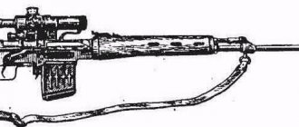
The 7.62 mm Dragunov sniper rifle is a sniper weapon and is designed to destroy various emerging, moving, open and camouflaged single targets.
The rifle is equipped with a PSO-1 sniper scope. The optical sight allows you to target infrared sources at night, as well as under unfavorable lighting conditions, when it is difficult to shoot at targets with an open sight.
When observing infrared sources, the infrared rays emitted by the source pass through the scope lens and affect the screen located in the focal plane of the lens. At the location of the infrared rays, a glow appears on the screen, giving a visible image of the source in the form of a round green color.
For shooting from a sniper rifle, rifle cartridges with ordinary, tracer and armor-piercing incendiary bullets or rifle sniper cartridges are used.
Fire from a sniper rifle is carried out in single shots.
When firing, cartridges are supplied from a box magazine with a capacity of 10 rounds.
Tactical and technical characteristics
If we talk about the SVD in numbers, its technical characteristics are as follows:
| Weight without ammunition, with optical sight | 4.5 kilograms |
| total length | 1225 millimeters |
| Barrel length | 620 millimeters |
| Receiver thickness | 88 millimeters |
| Height taking into account the installed sight PSO-1 | 230 millimeters |
| Nutrition | Magazines with a capacity of 10 cartridges 7.62x54 R |
SVD with a silent firing device, although in this case we are talking more about flameless firing.
As you can see, there can be no talk of any kilometers. Yes, open sights are graduated up to 1200 meters, yes, the sight allows you to fire up to 1300 meters. However, firing and hitting are two different concepts.
But if we talk about absolute records, there is one for SVD. In particular, the enemy was hit at a distance of 1350 meters. Such a hit was due not only to the skills of the shooter, favorable conditions at the time of the shot, but also to simple luck. No one else was able to repeat something similar from Dragunov’s sniper rifle. But with all this, we cannot say that the SVD’s performance characteristics do not meet current requirements.
Design of the Dragunov sniper rifle (SVD)
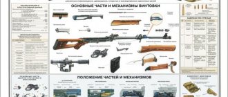
A sniper rifle consists of the following main parts and mechanisms:
1-barrel with receiver, open sight and butt; 2-receiver cover; 3-return mechanism; 4-bolt frame; 5-bolt, 6-gas tube with regulator, gas piston and pusher with spring, 7-barrel lining; 8-trigger mechanism; 9-fuse; 10-store; 11-cheek butt; 12-optical sight; 13-bayonet knife.
The sniper rifle kit includes:
I-accessory; 2-bag for carrying an optical sight and magazines; 3-case for optical sight; 4-bag for carrying winter mesh lighting device and oil can.
The sniper rifle is a self-loading weapon. Reloading a rifle is based on the use of the energy of powder gases removed from the barrel bore to the gas piston...
Purpose and design of accessories for a sniper rifle.
The accessory is used for disassembling, assembling, cleaning and lubricating a sniper rifle. Accessories include: 1 cleaning rod; 2-rubbing; 3-brush; 4-screwdriver; 5-punch; 6-penal; 7-oiler. Accessories (except for the oil can) are carried in a bag for the optical sight and magazines.
The cleaning rod is used to clean and lubricate the barrel, channels and cavities of other parts of the rifle. It consists of three links that are screwed together. On one link the ramrod has a head for connecting to the pencil case.
The wipe is intended for cleaning and lubricating the bore, as well as the channels and cavities of other parts of the rifle.
The brush is used to clean the bore with a RFS solution.
The screwdriver is used when disassembling and assembling the rifle, cleaning the gas chamber and gas tube, and also as a key when adjusting the position of the front sight in height. The hole in the middle is for a drift, used as a handle; for ease of use, the screwdriver is inserted into the side holes of the pencil case.
The drift is used to push out axles and studs.
The pencil case is used to store cleaning cloths, brushes, screwdrivers and drifts. The pencil case is used as a cleaning rod handle when cleaning and lubricating the rifle. The pencil case has two round holes for a cleaning rod and two oval holes for a screwdriver. The cover is used as a muzzle pad when cleaning the barrel.
The oil can is used to store lubricant.
Each sniper rifle comes with
a — a bag for carrying an optical sight and magazines; 1—pocket for an optical sight; 2—pocket for a napkin; 3—pocket for a light filter; 4—pocket for a pencil case; 5—pockets for stores; 6— pocket for a key-screwdriver; 7 - pocket for cleaning rod
b.—cover for the optical sight;
c—a bag for carrying a winter mesh lighting device. spare batteries and oil can;
Spare parts, tools and accessories for the optical sight:
1 - rubber cap for the toggle switch;
2 — light filter;
3— napkin:
4—case (protector) for spare light bulbs: 5—spare light bulbs;
6 — spare batteries;
7 - screwdriver key
Purpose, design of SVD parts and mechanisms
1.Barrel with receiver, open sight and butt
a) The barrel serves to direct the flight of the bullet. Inside the barrel has a channel with four rifling, winding from left to top to right, a chamber, a bullet entrance and a gas outlet.
On the outside, the barrel has: 1-front sight base: 2-gas chamber. 3-swivel; fixed part of the upper thrust ring: 5-moving part of the upper thrust ring; 6-upper thrust ring closure: 7-lower thrust ring: 8-sight block.
The base of the front sight has: 1- a stop for attaching a bayonet-knife 2- a slotted flash suppressor: 3- a groove for the front sight safety device: 4- a front sight safety device.
The gas chamber serves to direct powder gases from the barrel to the gas piston. An inclined hole is made inside the gas chamber. in the wall of the trunk. Consists of: 1-gas chamber: 2-gas tube latch.
The upper and lower thrust rings are used to attach the barrel linings. The lower thrust ring has barrel lining springs and a protrusion that prevents the linings from moving. The swivel is used to attach the belt carabiner to the rifle.
b) The receiver serves to connect the parts and mechanisms of the rifle, to ensure that the barrel bore is closed by the bolt and the bolt is locked; The receiver houses the bolt frame with the bolt and the trigger mechanism; it is closed with a lid on top.
The receiver has: 1-cutouts for “tyranny of the bolt; 2-bends; 3-cutouts in the folds; 4-reflective protrusion; 5-jumper; 6-axis jumper: 7-socket for placing the shutter frame with a spring; 8-cutout for magazine hook; 9-hole for fuse; 10-fixing recesses; 11 - receiver cover contact; 12-clamp of the contactor; 13-window for the store; 14-window for the trigger mechanism.
c) A mechanical (open) sight is used in case of damage (failure) of the optical sight. It consists of a sight and a front sight.
The sight consists of: 1-sight block: 2-rail; 3-yoke: 4-sector: 5-eye: 6-grevny sighting strap: 7-slot.
The sighting bar has a groove with a slot for aiming and cutouts for holding the clamp in the established position. On the sighting bar there is a scale with divisions from 1 to 12 and the letter P. The scale numbers indicate the firing range in hundreds of meters, P is a constant setting corresponding to sight 4.
The front sight is screwed into the fuse. On the fuse at the base of the front sight there are marks that determine the position of the front sight.
d) The butt serves for the convenience of operating the rifle. The stock is connected to the receiver using a connecting screw and a screw.
The butt has: 1-cutout forming the handle: 2-cutout for the butt cheek lock fastener: 3-window for the swivel: 4-swivel: 5-metal butt plate.
2. Receiver cover.
The receiver cover protects the parts and mechanisms located in the receiver from contamination. It houses the return mechanism.
It has: 1-protrusion: 2-cutouts for the passage of cartridges thrown out; 3-liner: 4-axle hole: 5-lug with semi-circular notch: 6-cylindrical boss: 7-spring retainer.
3.Return mechanism.
The return mechanism serves to return the bolt frame with the bolt to the forward position.
It consists of: 1-two return springs; 2-guide bushing; 3-guide rod; 4-earring. 5-axis earrings
4. Bolt frame.
The bolt frame serves to activate the bolt and firing mechanism.
The bolt frame has: 1-channel for the return mechanism: 2-channel for the bolt: 3-protrusion; 4-grooves for the receiver bends: 5-protrusions, 6-protrusion for lowering the self-timer lever: 7-reloading handle: 8-figure protrusion: 9-groove for the barrel trigger column.
5.Shutter
The bolt serves to send the cartridge into the chamber, close the channel for breaking the primer and remove the cartridge case (cartridge) from the chamber.
It consists of: 1-bolt frame; 2-drummer; 3-ejector; 4-spring; 5-axis ejector; 6-pin ejector; 7-cutout for the bottom of the sleeve; 8-cutout for ejector; 9-combat protrusions; 10-leading projection; 11-bevel; 12-longitudinal groove for reflective protrusion; 13-hole for the ejector axis; 14- firing pin; 15-ledge for hairpin; 16-ejector hook; 17-cut for the axle.
6.Gas tube with regulator, gas piston and pusher with spring.
The gas tube serves to direct powder gases from the barrel to the gas piston. An inclined hole is made inside the gas tube in the barrel wall. Outside the gas tube there is a tetrahedral thickening for the pencil case key.
The regulator has two settings, designated by numbers 1 and 2. It is installed on division 1 against the marks on the latch of the gas tube. If you shoot for a long time without cleaning and lubrication and there is a lot of wear on the parts, there may be a delay or incomplete release of the moving parts. In this case, the regulator is switched to setting 2. To do this, you need to insert the edge of the sleeve or cartridge into the hooks of the regulator and turn the regulator.
Rearranging the gas regulator
The gas piston is placed in a gas tube and serves to transmit the pressure of the powder gases to the pusher.
A pusher with a spring serves to pull the bolt frame back when firing.
The pushrod spring serves to return the pushrod and gas piston to the forward position.
7
.Barrel linings.
Barrel linings serve to protect the sniper’s hands from burns when shooting.
8.Trigger mechanism
The trigger mechanism is used to decock and cock the self-timer, to ensure single-fire, to stop firing, to prevent a shot when the bolt is unlocked, and to put the rifle on safety.
The housing is used to house parts of the trigger mechanism.
The trigger with a mainspring is used to strike the firing pin. The trigger has a cocking mechanism with a groove for pulling the trigger.
The self-timer is used to automatically release the trigger from the self-timer cocking when firing, as well as to prevent the trigger from being released when the bolt is unlocked.
The sear serves to hold the trigger in the rearmost position after firing,
The trigger with a spring is used to remove the sear from under the cocking action.
1-body; 2-trigger; 3-mainspring; 4-self-timer; 5-sear; 6-trigger 7-trigger spring; 8- safety bracket; 9-window for the tail of the trigger; 10-hole for the trigger axis; 11-hole for the sear axis; 12-hole for the self-timer axis; 13-hole for the fuse axis; 14-hole for the trigger axis; 15-cutouts for the lintel axis; 16 combat platoon; 17-platoon self-timer; 18-sear self-timer; 19-self-timer lever; 20-sear hooks; 21-tail whispered; 22-trigger pull; 23-axis; 24-magazine latch; 25-hook for the end of the trigger spring; 26-shield limiter.
Fuse
The fuse serves to lock the sear and trigger and at the same time limit the rear movement of the bolt frame, thereby eliminating the possibility of an accidental shot, as well as to secure the trigger mechanism in the receiver.
1-axis; 2-thickened part of the axis; 3-axis protrusion; 4-shield; 5-cutout for the sear tail; 6-shield protrusion; 7-cutout for limiting the shield.
10.Shop.
The magazine is used to place cartridges and feed them into the barrel
1-body; 2-cover; 3-stop bar; 4-spring; 5-supplier; 6-folds; 7-hook; 8-support ledge; 9-protrusion feeder.
11.Butt cheek
The butt cheek is used for ease of operation of the rifle and is used only when shooting with an optical sight.
1-wooden base; 2-meat stuffing; 3-loop; 4-clasp; 5-clip clip.
12.Optical sight.
The optical sight is the main sight of a sniper rifle.
The optical sight consists of mechanical and optical parts.
a- left view; b- right;
1-body; 2-bracket; 3-upper handwheel; 4-side handwheel; 5-retractable hood; 6-rubber eyecup; 7-clamp screw; 8-handle clamping screw; 9-engine; 10-adjusting nut; 11-pointer; 12-lens cap; 13-socket nut; 14-pshala; 15-connecting screw, 16-locking screw, 17-flag fluorescent screen; 18-housing for battery; 19-cap with stop; 20-toggle switch; 21-light bulb; 22-stop; 23-wire; 24-pin screw.
The mechanical part of the sight includes:
1-body; 2-top and side handwheels; 3-sight reticle lighting device; 4-pull-out hood; 5-rubber eyecup and cap.
The housing serves to connect all parts of the sight on the rifle.
The upper handwheel is used to install the sight, the side handwheel is used to introduce lateral corrections. They are identical in design and have a handwheel housing, a spring washer, an end nut and a connecting screw. In the housing, the two outer holes serve as locking screws.
On the body of the upper handwheel there is a main sight indicator with divisions from 1 to 10. The scale numbers indicate the firing range in hundreds of meters.
On the body of the side handwheel there is a scale of lateral corrections with divisions from O to 10 in both directions; The value of each division corresponds to one thousandth (0-01).
On the upper part of the handwheel housings there is an additional scale used when aligning the sight; the scale division value is 0.5 thousandths. The settings of the main scale of the upper handwheel up to division 3 are fixed after one division. From division 3 to division 10, the settings of this handwheel, as well as all settings of the side handwheel scale, are fixed every half division. On the end nuts of the upper and side handwheels, an arrow indicates the direction of rotation of the handwheels (“Up STP”, “Down STP”) - on the upper handwheel, (“Right STP”, “Left STP”) - on the side handwheel.
The reticle illumination device is used to illuminate the sight reticle when shooting at dusk and at night.
It consists of: a housing with a contact screw; batteries; cap with stop; wires; light bulbs; toggle switch.
1-case for battery; 2-cap with stop; 3-shielded wire
To illuminate the sight reticle at temperatures from +2 and below, you must use a winter reticle illumination device.
The eyecup is designed for correct installation of the eye and convenient aiming.
A retractable lens hood serves to protect the lens during inclement weather from rain, snow, and direct sunlight when shooting against the sun, thereby eliminating reflections that unmask the sniper.
The rubber cap protects the lens from contamination and damage.
The optical part of the sight includes:
1-lens, 2-flip system; 3-grid; 4-luminescent screen; 5-eyepiece.
The lens is used to obtain a reduced and inverted image of the observed object. It consists of three lenses, two of which are glued together.
The turning system is designed to give the image a normal position. It consists of four lenses glued in pairs.
The sight reticle is used for aiming. It is made on glass mounted in a movable frame (carriage).
The main square for shooting. yesoam
Lateral correction scale
The scale of lateral corrections is indicated at the bottom with the number 10, which corresponds to ten thousandths, the distance between the vertical lines of the scale corresponds to one thousandth—0-01.
Additional squares for long-range shooting
Rangefinder scale
The eyepiece is designed to view the observed object in a magnified and direct image. It consists of three lenses, two of them are glued.
The fluorescent screen is used to detect infrared light sources. It is a thin plate of a special chemical composition, which is laid between two glasses. The screen has a window with a light filter in the frame for charging the screen and a screen switching flag.
13. Bayonet knife
The bayonet is attached to a sniper rifle before an attack and is used to defeat the enemy in hand-to-hand combat. The rest of the time it is used as a knife, saw and scissors.
1-blade; 2-handle; 3-cutting edge, 4-saw; 5-cutting edge; 6-hole; 7-ring; 8-longitudinal groove; 9-latch; 10-safety ledge; 11-hole for belt; 12-metal tip; 13-pin connection screw.
The scabbard is used to carry a bayonet-knife on a belt; in addition, it is used in conjunction with a bayonet-knife for cutting wire.
1-protrusion-axis; 2-stop; 3-plastic body; 4-pendant with loop.
History of the Dragunov sniper rifle
The development of a specialized sniper rifle for the Soviet Army began in the second half of the 50s of the last century.
The impetus for the development was a change in the staffing of motorized rifle units, which included a sniper. The general requirements for the rifle were formalized in the form of technical specifications of the GRAU of the General Staff of the SA by 1958:
- use a Mosin rifle cartridge (7.62*54 mm) as ammunition;
- have a self-loading principle of operation and not exceed the dimensions of the SVT-40 and Mosin rifles;
- the stock of cartridges in the store is at least 10 pieces;
- the ability to conduct effective fire at a distance of up to 600 m.
Rifles from several design bureaus, including E.F., were presented for competitive testing. Dragunova, S.G. Simonov and A.S. Konstantinov. Comparative shooting took place at the training ground in Shchurovo (Moscow region).
The samples of Simonov and Konstantinov demonstrated good automatic performance along with low combat accuracy.
The SSV-58 self-loading rifle designed by Dragunov showed high accuracy characteristics, but at the same time the commission noted the low reliability of the weapon, which became unsuitable for use after 500...600 rounds.
All three versions of the rifle received recommendations for improvement and were tested again in 1960. After this cycle of tests, Simonov Design Bureau’s weapon was considered unsuccessful (due to low accuracy compared to the standard), and the remaining two samples were sent for revision.
In particular, there were complaints about the operation of the cartridge feeding mechanism on the Dragunov rifle.
The third cycle of tests took place at the end of 1961 - beginning of 1962 and revealed the final winner - the Dragunov rifle, which surpassed its competitor in terms of fire accuracy.
Konstantinov’s weapon was rejected for the ability to fire only with an optical sight and the location of the cartridge ejection window too close to the shooter’s face.
By mid-1962, the first batch of 40 copies of the SSV-58 entered the troops. Based on operating experience, adjustments were made to the design, and in 1963 mass production of weapons began under the designation Dragunov self-loading rifle (GRAU code 6B1). At the same time, the PSO-1 model optical sight (code 6Ts1) entered service.
Early samples of the SVD had a barrel with a rifling pitch of 320 mm, which corresponded to conventional bullets and provided high accuracy parameters. When using the modernized B-32 armor-piercing incendiary bullets, increased dispersion began to be observed.
Therefore, in 1975, the pitch was reduced to 240 mm, which somewhat reduced the accuracy when using conventional bullets, but significantly improved the accuracy of fire.
Incomplete disassembly and reassembly after incomplete disassembly
Disassembly of a sniper rifle can be incomplete or complete :
incomplete - for cleaning, lubricating, inspecting the rifle
full - for cleaning when the rifle is heavily soiled, after being in the rain or snow, when switching to a new lubricant and during repairs. Frequent disassembly of the rifle is not allowed, as it accelerates the wear of parts and mechanisms.
Disassemble and reassemble the rifle on a table or clean mat; Place parts and mechanisms in the order of disassembly, handle them carefully, do not place one part on top of another, do not use excessive force or sharp blows. When assembling a rifle, compare the numbers on its parts; The number on the receiver must correspond to the numbers on the bolt carrier, bolt, trigger mechanism, receiver cover, optical sight and other parts of the rifle.
Training in disassembly and assembly on combat rifles is permitted only in exceptional cases, subject to special care in handling parts and mechanisms.
The procedure for partial disassembly of a sniper rifle:
1. Separate the store. Hold the magazine with your right hand, pressing the latch with your thumb, move the bottom of the magazine forward and separate it. After this, check to see if there is a cartridge in the chamber, to do this, lower the safety down, pull the charging handle back, inspect the chamber and release the handle.
2. Separate the optical sight. Lift the handle of the clamping screw and turn it towards the eyecup until it stops, move the sight back and separate it from the receiver.
3.Separate the butt cheek. Turn the cheek lock clasp down, remove the loop from the hook and clip and separate the cheek.
4. Separate the receiver cover with the return mechanism. Turn the receiver cover lock back until it is locked into place, lift up the rear part of the receiver cover and separate the cover with the return mechanism.
5. Separate the bolt frame from the bolt. Pull the bolt frame back as far as it will go, lift it and separate it from the receiver.
6. Separate the bolt from the bolt frame. Pull the bolt back, turn it so that the leading lug of the bolt comes out of the figured cutout of the bolt frame and move the bolt forward.
7. Separate the trigger mechanism. Turn the safety up to a vertical position, move it to the right and separate it from the receiver, holding the trigger guard and moving it downward to separate the trigger mechanism from the receiver.
8. Separate the barrel linings. Press the contactor of the upper thrust ring against the gas tube until the bend of the contactor comes out of the cutout of the ring and turn the contactor to the right until it stops; move the moving part of the upper thrust ring forward; pressing the barrel pad down and moving it to the side separate it from the barrel.
If it is difficult to separate the barrel linings, insert the cutout of the pencil case key into the window of the lining and move downwards and to the side to separate the barrel lining.
9. Separate the gas piston and pusher with the spring. Pull the pusher back, remove its front end from the piston seat and separate the piston from the gas tube; insert the front end of the pusher into the gas tube; press the pusher spring until it leaves the channel of the aiming block and separate the pusher with the spring, and then separate the spring from the pusher.
The procedure for assembling a sniper rifle after partial disassembly
- Place the spring on the rear end of the pusher; insert the front end of the pusher into the gas tube, tighten the spring and insert the rear end of the pusher with the spring into the channel of the aiming block; pull the pusher back and move its front end out of the gas tube to the side; insert the gas piston into the gas tube and the front end of the pusher into the piston socket.
- Attach the barrel linings. Insert the rear (widened) end of the right (left) barrel lining into the lower thrust ring with the cutout of the lining towards the sight and, pressing the lining down, attach it to the barrel; push the moving part of the upper thrust ring onto the tip of the linings and turn the closure of the upper thrust ring towards the gas tube until its bend enters the cutout on the ring.
- Attach the firing mechanism. Place the cutouts of the trigger mechanism housing behind the axis of the receiver jumper and press the trigger mechanism to the receiver; insert the fuse axis into the hole in the receiver; Turn the fuse to a vertical position, press it tightly to the receiver and turn down until the protrusion of the shield enters the lower locking recess of the receiver.
- Attach the bolt to the bolt frame. Insert the cylindrical part of the bolt into the frame channel; turn the bolt so that the leading protrusion fits into the figured cutout of the bolt frame, and push the bolt forward until it stops.
- Attach the bolt carrier to the bolt. While holding the bolt in the forward position, insert the guide protrusions of the bolt frame into the cutouts of the receiver bends, press the bolt frame against the receiver with a slight force and push it forward.
- Attach the receiver cover with the return mechanism. Insert the return mechanism into the bolt frame channel; compressing the return springs, insert the protrusions on the front end of the cover into the cutouts on the lower thrust ring; press the rear end of the cover until it is completely adjacent to the receiver; Turn the receiver cover lock forward until it engages the lock.
- Attach the butt cheek. Place the cheekpiece on the top of the butt with the clasp to the right opposite the cutout for it; put the loop on the hook of the clip and turn the clasp up.
- Attach the optical sight. Align the grooves on the trailer bracket with the tabs on the left wall of the receiver; push the sight forward as far as it will go and turn the clamping screw handle toward the lens until its bend fits into the cutout on the bracket.
9. Attach the magazine. Insert the magazine hook into the receiver window and turn the magazine toward you so that the latch jumps over the magazine's support protrusion.
Connecting and unlocking the bayonet knife
1.Connecting the bayonet-knife.
Remove the bayonet from the sheath; push it with the grooves onto the stop of the front sight base, and with the ring onto the flash suppressor until the latch is completely closed.
2. Unlocking the bayonet. With the thumb of your right hand, press the latch, push the bayonet forward and separate it from the rifle, place the bayonet in the sheath.
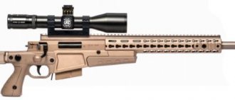
Russian sniper rifles
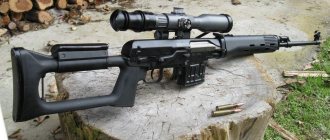
SVD-S sniper rifle with PSO-1 sight, butt folded down
The experience of local conflicts - and above all, the Afghan war - pointed to the need to adopt a model of sniper weapons intended for airborne and air assault units, and more compact for transportation, on the march, during landing.
In 1995, a modification of the 7.62-mm SVDS sniper rifle (Dragunov sniper rifle with a folding stock, index 6VZ) was adopted for service. The permanent stock is replaced by a plastic pistol grip and a lightweight, right-folding skeletal stock with a plastic shoulder rest. The butt is equipped with a non-removable rotating “cheek” and a tube - for holding the butt with your left hand when shooting from a rest.
The plastic barrel linings are similar to the SVD. Folding the stock does not require removing the optical sight. The design of the mechanism for fixing the buttstock in the “combat” position ensures rigidity of fixation and compensation for wear of parts during operation.
SVD S sniper rifle with folded stock, with PSO-1 sight
The gas outlet unit has been improved, the flame arrester has been changed and shortened. The regulator built into the gas outlet unit was initially excluded to simplify the design, but now the SVDS is offered in a version with a regulator. The walls of the barrel were thickened, which reduced its heating and vibrations when fired. Reinforcement of the receiver increased the stability of the optical sight mount. The main sight is the PSO-1M2 optical sight. SVDS is intended primarily for airborne units.
SVDS, like the basic SVD,. can be equipped with a removable light bipod attached in front of the forend. “Night” modifications of the SVDS rifle correspond to the basic SVD: - SVDSN1 - with NSPU night sight; - SVDSN2 - with NSPUM night sight; - SVDSNZ - with night sight NSPU-3. Note that in 1992, another “shortened” version of the SVD was presented for the same purpose - the DSV rifle (“airborne sniper rifle”) with a barrel shortened to 605 mm, but it was not accepted for service.
Tactical and technical characteristics of SVD-S
Caliber: 7.62 mm Cartridge: 7.62 x 53 R Weight of weapon with optical sight and magazine without cartridges: 4.68 kg Length of weapon: with folded butt, without bayonet: 1135 mm with folded butt: 875 mm Barrel length: 565 mm Muzzle velocity: 810 m/s Combat rate of fire: 30 rounds/min Sighting range: with optical sight: 1300 m with mechanical sight: 1200 m Magazine capacity: 10 rounds
Photo review of the SVD-S sniper rifle
Operation of parts and mechanisms of the Dragunov sniper rifle (SVD), during loading and shooting
Position of parts and mechanisms before loading
The bolt carrier with the bolt is in the extreme forward position; The bore is opened by a bolt. The bolt is rotated around the longitudinal axis to the left, its lugs are located in the cutouts of the receiver - the bolt is locked. Return springs have the least compression.
The gas piston and pusher are in the extreme forward position. The pusher spring is at its lowest preload.
The self-timer lever is turned forward and down under the action of the bolt frame protrusion and the self-timer is turned off.
The trigger is released and rests against the bolt. The hammer is moved forward under the action of the trigger. The mainspring is at its lowest compression; with its loop it presses the trigger to the bolt, with the long end it presses the tail of the sear against the stop, and with the short end it presses down on the tail of the self-timer.
The trigger is pulled forward under the action of a spring. The trigger spring presses in a loop on the rear end of the rod, and the rod with its upper plane with a hook rests against the sear jumper.
The fuse is in the uppermost position, closes the cutout in the receiver cover and limits the rearward movement of the bolt frame; the thickened part of the fuse axis is located under the shield stop and above the tail of the sear and prevents their rotation (locks the sear and trigger). Operation of parts and mechanisms during loading.
When attaching the magazine, its hook enters the cutout of the receiver, and the supporting protrusion slides over the latch and the magazine is held in the receiver window. The upper cartridge, resting against the bolt frame from below, lowers the cartridges somewhat into the magazine, compressing its spring.
When the safety is set to the “FIRE” position, a cutout opens for movement of the reloading handle, the tail of the sear and the trigger are released.
When the bolt frame is pulled back to the free stroke length, it, acting with the front bevel of the leading cutout on the leading lug of the bolt, turns the bolt to the right, the bolt lugs come out of the cutouts of the receiver - the bolt is unlocked; the protrusion of the bolt frame releases the self-timer lever, and the self-timer sear is pressed against the plane of the trigger under the action of the short end of the mainspring on the tail of the self-timer.
As the bolt frame is further retracted, the bolt moves back along with it, opening the barrel; the return springs are compressed; the trigger rotates back under the action of the protrusion and then the bevel on the groove of the bolt frame; the mainspring is twisted; the cocking cock of the trigger passes behind the hooks of the sear, and the self-timer sear jumps behind the self-timer cocking.
As soon as the lower plane of the bolt frame passes the window for the magazine, the cartridges, under the action of the magazine spring, rise to the top until the upper cartridge stops in the bend of the magazine wall.
The movement of the bolt frame with the bolt in the rearmost position is limited by the receiver cover liner.
When the bolt frame is released, it, together with the bolt, is fed into the front under the action of the return mechanism; The bolt rammer pushes the upper cartridge out of the magazine, sends it into the chamber and closes the barrel. When the bolt approaches the breech end of the barrel, the ejector hook jumps over the rim of the sleeve; The bolt, under the action of the bevel of the bolt protrusion, receives an initial rotation, and then, under the action of the figured cutout of the bolt frame moving in front of the leading protrusion, it rotates around its axis to the left; the lugs of the bolt enter into the cutouts of the receiver, and the leading lug of the bolt enters the straight section of the figured cutout of the bolt frame - the bolt is locked. When approaching the extreme forward position, the bolt frame with its protrusion rotates the self-timer lever forward and down, removing the self-timer sear from under the self-timer cocking of the trigger; The trigger rotates under the action of the mainspring and is cocked.
The cartridges in the magazine, under the action of a spring, rise upward until the upper cartridge stops in the bolt frame.
When the rifle is put on safety, the shield closes the cutout for the reloading handle and stands in the way of its backward movement, and the thickened part of the axis stands against the tail of the sear and the shield stop (locks the sear and the trigger).
Operation of parts and mechanisms during shooting.
To fire a shot, you must remove the rifle from the safety lock and pull the trigger.
When you press the tail of the trigger, it moves back along with the rod;
the rod hook turns the sear and disengages it from the cocking trigger. The trigger, under the action of the mainspring, rotates on its axis and vigorously strikes the firing pin. A shot occurs.
The bullet, under the influence of powder gases, moves along the bore; as soon as it passes the gas outlet, part of the gases rushes through this hole into the gas chamber and puts pressure on the gas piston, and the latter on the pusher.
The pusher, compressing its spring, hits the front platform of the bolt frame and throws the bolt frame and bolt back. Moving back, the bolt frame with the front bevel of the figured cutout turns the bolt around the longitudinal axis, and its lugs emerge from the cutouts of the receiver - the bolt is unlocked and the barrel channel is opened; the protrusion of the bolt frame releases the self-timer lever, and the self-timer sear is pressed against the plane of the trigger. By this time the bullet flies out of the barrel.
The gas piston and pusher move backward, compressing the pusher spring, until the pusher crown stops in the aiming block. Subsequently, the compressed spring of the pusher pushes the pusher and gas piston forward until the piston head stops at the end of the gas tube.
The bolt frame with the bolt continues to move backward by inertia; the cartridge case, held by the ejector hook, collides with the reflective protrusion of the receiver and is thrown out.
At the end of the turn, the trigger hits the front of the trigger rod, lowers it down and disconnects it from the sear, and then cocks the self-timer. The sear, under the action of the long end of the mainspring, returns to its original position - against the cocking of the hammer.
To fire the next shot, you must release the trigger and press it again. When the trigger is released, under the action of the trigger spring, together with the rod, it will move forward and the hook of the rod will jump over the sear jumper, and when the trigger is pressed, the sear will disengage with the cocking of the hammer and release the hammer - another shot will fire.
After firing the last cartridge in the magazine, the magazine feeder, rising upward, acts with its protrusion on the bolt mainframe and pushes it out of the receiver socket, compressing the mainframe spring.
When the bolt frame moves forward, the bolt rammer rests on the bolt axle and the bolt frame stops in this position, thereby indicating that all the cartridges in the magazine have been used up. When the magazine is separated from the rifle, the bolt frame remains on the bolt frame, since the bolt frame spring cannot lower the bolt frame, which is pressed by the bolt. In order for the bolt frame to lower into its socket, it is necessary to move the bolt frame back and release it.
Purpose, design of rifle parts and mechanisms
11. Trunk
(Fig. 19) serves to direct the flight of the bullet. Inside, the barrel has a channel with four rifling, winding from left to top to right, a chamber, a bullet entrance and a gas outlet. The bore caliber is 7.62 mm.
On the outside, the barrel has: a front sight base, a gas chamber, a sling swivel, upper and lower thrust rings of the barrel linings, a sight block and a cutout on the breech end for the ejector hook.
Rice. 19. Barrel:
1 – base of the front sight; 2 – gas chamber; 3 – moving part of the upper thrust ring; 4 – fixed part of the upper thrust ring; 5 – barrel linings; 6 – sight block; 7 – lower thrust ring; 8 – contactor of the upper thrust ring; 9 – swivel
Front sight base
(Fig. 20) has a stop for attaching a bayonet-knife, a slotted flash suppressor and a groove for the front sight safety.
Gas chamber
(Fig. 21) serves to direct powder gases from the barrel to the gas piston. It consists of a gas tube with a hole, a regulator, a gas piston and a gas tube latch. An inclined hole is made inside the gas chamber, combined with a gas outlet hole in the barrel wall. Outside the gas tube there is a tetrahedral thickening for the pencil case key.
Rice. 20. Front sight base:
1 – knife bayonet stop; 2 – flame arrester; 3 – groove for the front sight safety device; 4 – front sight fuse
Rice. 21. Gas chamber:
1 – gas chamber; 2 – gas tube; 3 – regulator; 4 – gas piston;
5 – gas tube latch; 6 – tetrahedral thickening for the pencil case key;
7 – gas piston head; 8 – socket for pusher
Gas piston
is placed in a gas tube and serves to transmit the pressure of the powder gases to the pusher. It has a head and a socket for the front end of the pushrod.
Pusher with spring
(Fig. 22) serves to move the bolt frame back when firing.
It has a rim to stop the spring and limit the backward movement of the pusher. The pushrod spring serves to return the pushrod and gas piston to the forward position.
Rice. 22. Pusher:
1 – corolla; 2 – pusher spring
Regulator
has two settings, designated by numbers 1 and 2. It is installed on division 1 against the marks on the latch of the gas tube. When shooting for a long time without cleaning and lubrication, a delay may occur - incomplete waste of the moving parts. In this case, the regulator is switched to setting 2. To do this, it is necessary to insert the edge of the sleeve or cartridge into the hooks of the regulator (Fig. 23) and turn the regulator.
Rice. 23. Rearranging the gas regulator
The upper and lower thrust rings are used to attach the barrel linings to the barrel. The lower thrust ring has receiver lining springs and a protrusion that prevents the linings from moving, as well as cutouts for the receiver cover protrusions. The upper thrust ring consists of two parts - stationary and moving. On the stationary part there are stops (bends) for holding the linings, and on the moving part there is a closure for securing the upper thrust ring to the attached barrel linings. Ventilation windows are made in the walls of the linings.
12. Receiver
(Fig. 24) serves to connect parts and mechanisms of the rifle, to ensure that the barrel bore is closed by the bolt and the bolt is locked; the receiver houses the bolt frame with the bolt and the trigger mechanism; It is closed with a lid on top.
Rice. 24. Receiver:
1 – cutouts for locking the shutter; 2 – bends; 3 – cutouts in the folds; 4 – reflective protrusion; 5 – jumper; 6 – axis of the jumper; 7 – shutter stop; 8 – cutout for magazine hook; 9 – holes for fuse; 10 – fixing recesses; 11 – receiver cover contact; 12 – contactor lock; 13 – window for the store; 14 – window for the trigger mechanism; 15 – butt
The receiver has:
– inside there are cutouts for locking the bolt, the rear walls of which are lugs, and on the left side there is a protrusion with a bevel for preliminary rotation of the bolt at the beginning of its locking, bends with cutouts for directing the movement of the bolt frame and bolt; reflective protrusion with a bevel for reflecting cartridges; a jumper with an axis for connecting the trigger mechanism and a socket for placing a shutter stop with a spring; cutout for magazine hook;
– in the side walls there are holes for the fuse and holes for the receiver cover lock; on the right wall there are two fixing recesses for installing a fuse and a locking mechanism for the receiver cover; on the left wall there are protrusions for attaching (attaching) an optical sight;
– below – a window for the magazine and a window for the trigger mechanism.
The butt is attached to the receiver.
13. Receiver cover
(Fig. 25) protects parts and mechanisms placed in the receiver from contamination. It houses the return mechanism. In front it has protrusions for fixing the cover in the lower thrust ring of the barrel; on the right side there are cutouts for the passage of cartridges thrown out and for the movement of the reloading handle; rear – liner; in the side walls there are holes: on the left - for the axis of the return mechanism earring, on the right - for pushing out this axis with a drift. The insert has a window for the return mechanism earring; a protrusion with a semicircular recess for attaching the cover to the receiver using a lock; a cylindrical protrusion, which, together with the front wall of the liner, absorbs the impact of the bolt and bolt frame in the rearmost position; a hole for the axis of the earring of the return mechanism and a spring retainer of the axis of the earring.
Rice. 25. Receiver cover:
1 – protrusions 2 – cutouts; 3 – liner; 4 – hole for pushing out the axle; 5 – protrusion with a semicircular recess; 6 – cylindrical protrusion; 7 – spring clamp
14. Return mechanism
(Fig. 26) serves to return the bolt frame with the bolt to the forward position.
It consists of two identical return springs, a guide bushing, a guide rod and an earring with an axis, with the help of which it is secured in the receiver cover liner.
Rice. 26. Return mechanism:
1– return springs; 2 – guide sleeve; 3 – guide rod; 4 – earring; 5 – earring axis
15. Bolt carrier
(Fig. 27) serves to activate the bolt and trigger mechanism.
Rice. 27. Bolt carrier:
1 – channel for the return mechanism; 2 – channel for the shutter; 3 – protrusion; 4 – grooves for receiver bends; 5 – guide protrusions; 6 – protrusion for lowering the self-timer lever; 7 – reloading handle; 8 – figured cut; 9 – groove for passage of the trigger head
The bolt frame has: inside - an upper channel for the return mechanism, a lower channel for the bolt, a longitudinal groove for the passage of the reflective protrusion (this groove is absent in rifles of the first release) and two side channels made for lightness; at the back there is a protrusion that eliminates the possibility of firing when the bolt is not closed and serves to rotate the trigger when the bolt frame moves back; on the sides there are grooves with guide protrusions for moving the bolt frame along the bends of the receiver; on the left side behind there is a protrusion for lowering (rotating) the self-timer lever; on the right side in front there is a handle for reloading the rifle; at the bottom there is a shaped cutout to accommodate the leading protrusion of the bolt and a groove with a bevel for the passage of the trigger head.
16. Gate
(Fig. 28) serves to send the cartridge into the chamber, close the barrel bore, break the primer and remove the cartridge case (cartridge) from the chamber. It consists of a frame, a firing pin, an ejector with a spring and an axis, and a firing pin.
Shutter body
has: on the front section - two cylindrical cutouts for the bottom of the sleeve and the ejector; two recesses that prevent the bolt from hitting the breech end of the barrel; three lugs that, when the bolt is locked, fit into the cutouts of the receiver; on the right lug there is a leading lug for turning the bolt when locking and unlocking; on the left protrusion there is a bevel for preliminary rotation of the bolt when locking; the lower protrusion is a cartridge rammer; on the left side there is a longitudinal groove for the passage of the reflective protrusion of the receiver; in the thickened part of the bolt frame there are transverse holes for the ejector axis and the firing pin. A channel is made inside the bolt frame to accommodate the firing pin.
Rice. 28. Shutter:
1 – shutter body; 2 – drummer; 3 – ejector; 4 – ejector spring; 5 – ejector axis;
6 – striker pin; 7 – cutout for the bottom of the sleeve; 8 – cutout for ejector; 9 – combat ledges;
10 – leading protrusion; 11 – bevel; 12 – longitudinal groove for the reflective protrusion;
13 – hole for the ejector axis; 14 – firing pin; 15 – ledge for the hairpin;
16 – ejector hook; 17 – cutout for axle
Drummer
has a striker and a ledge to limit the movement of the striker with a pin.
Ejector with spring
serves to remove the cartridge case (cartridge) from the chamber and hold it until it meets the reflective protrusion of the receiver. The ejector has a hook for gripping the cartridge case, a socket for the spring and a cutout for the axle.
17. Trigger mechanism
(Fig. 29) is used to release the trigger from combat cocking and cocking the self-timer, ensuring single fire, stopping firing, preventing a shot when the bolt is unlocked and to put the rifle on safety.
The trigger mechanism consists of a body, a trigger with a mainspring, a self-timer, a sear and a trigger with a spring.
Frame
has: at the bottom – a safety bracket, a window for the tail of the trigger; in the side walls there are three holes with cutouts on the right side for the axes of the trigger, sear and self-timer, as well as holes for the safety axis and the trigger axis; in front – cutouts for the axis of the receiver jumper; at the back are hooks for the ends of the trigger spring; inside there is a stand with a cutout to direct the movement of the trigger pull and a limiter for the tail of the sear.
Rice. 29. Trigger mechanism:
1 – body; 2 – trigger; 3 – mainspring; 4 – self-timer; 5 – sear, 6 – trigger; 7 – trigger spring; 8 – safety bracket; 9 – window for the tail of the trigger, 10 – hole for the axis of the trigger; 11 – hole for the sear axis, 12 – hole for the self-timer axis; 13 – hole for the fuse axis; 14 – hole for the trigger axis; 15 – cutouts for the lintel axis; 16 – combat platoon; 17 – self-timer cocking, 18 – self-timer sear; 19 – self-timer lever; 20 – sear hooks; 21 – whispered tail; 22 – trigger pull; 23 – axles; 24 – magazine latch; 25 – hook for the end of the trigger spring; 26 – shield limiter
Trigger with mainspring
serves to strike the striker. The trigger has a combat cock with a groove for the trigger pull, a self-timer cock, trunnions and a hole for the axle. The mainspring is put on the trigger pins and acts with its loop on the trigger, with its long end on the tail of the sear, and with its short end on the tail of the self-timer.
Self-timer
serves to automatically release the trigger, decocking the self-timer when firing, and also to prevent the trigger from being released when the bolt is unlocked. It has a sear for holding the trigger on the self-timer cocking, a lever for disconnecting the self-timer sear from cocking the self-timer trigger by the protrusion of the bolt frame when it approaches the forward position, a tail for the short end of the mainspring and a hole for the axle.
sear
serves to hold the trigger in the rearmost position after firing. The sear has hooks to hold the hammer cocked, a jumper to hook the trigger rod and a tail for the long end of the mainspring.
Trigger with spring
serves to remove the sear from under the cocking trigger. It has a hook rod, a guard stop, axle holes and a tail.
The magazine latch with a spring is placed on its axis in the trigger mechanism housing.
18. Fuse
(Fig. 30) serves to lock the sear and trigger and at the same time limit the rear movement of the bolt frame, thereby eliminating the possibility of an accidental shot, as well as to secure the trigger mechanism in the receiver. The fuse has: an axis that secures the trigger mechanism on the receiver, with a thickened part for locking the sear and protrusions for holding it in the receiver; a shield with a protrusion that covers the cutout for movement of the bolt handle when the rifle is put on safety. On the thickened part of the axis there are cutouts for the sear tail and for the shield limiter. The lower position of the fuse corresponds to its installation for firing, and the upper position corresponds to the safety.
Rice. 30. Fuse:
1 – axis; 2 – thickened part of the axis; 3 – axis protrusion; 4 – shield; 5 – cutout for the sear tail;
6 – protrusion of the shield; 7 – cutout for the shield limiter
19. Butt with cheek
(Fig. 31) serves for ease of operation with a rifle.
Rice. 31. Butt with cheek:
1 – cutout forming a handle; 2 – cutout for the butt cheek lock fastener; 3 – window; 4 – swivel; 5 – metal butt plate; 6 – cheek; 7 – wooden base; 8 – soft padding; 9 – loop; 10 – fastener; 11 – clip hook
Butt
has: a cutout that forms a handle and serves to accommodate the thumb of the right hand, and a cutout for fastening the butt cheek lock; window with sling swivel; metal butt plate; screw securing the receiver cover lock. The stock is connected to the receiver using a connecting screw and a screw.
Butt cheek
used only when shooting with an optical sight. It consists of a wooden base, soft padding with leather covering and a lock for attaching the cheekpiece to the butt. The lock has a clip with a hook and a clasp with a loop.
20. Sights
serve for aiming the rifle when shooting at targets at various distances.
The sighting devices of a sniper rifle consist of a PSO-1 optical sight and a mechanical (open) sight.
21. Optical sight
(Fig. 32) is the main sight of a sniper rifle. Sight magnification is 4x, field of view is 6°. The optical sight consists of mechanical and optical parts.
Rice. 32. Optical sight:
a – left view; b – right view; 1 – body; 2 – bracket; 3 – upper handwheel; 4 – side handwheel; 5 – retractable hood; 6 – rubber eyecup; 7 – clamping screw; 8 – handle of the clamping screw; 9 – engine; 10 – adjusting nut; 11 – pointer; 12 – lens cap; 13 – end nut; 14 – scale; 15 – connecting screw; 16 – locking screw; 17 – fluorescent screen flag; 18 – battery housing; 19 – cap with stop; 20 – toggle switch; 21 – light bulb; 22 – stop
The mechanical part of the sight includes: a body, top and side handwheels, a reticle illumination device, a retractable hood, a rubber eyecup and a cap.
The optical part of the sight (Fig. 33) includes: a lens, a wrapping system, a reticle, a fluorescent screen and an eyepiece.
Rice. 33. Optical part of the sight:
1 – lens; 2 – wrapping system; 3 – mesh; 4 – eyepiece; 5 – fluorescent screen
The housing serves to connect all parts of the sight on the rifle. The bracket has grooves, a stop, a clamping screw, a clamping screw handle, a slider with a spring and an adjusting nut. Pointers (indices) for sight settings and lateral corrections and a lens cap are attached to the body.
Upper handwheel
serves to install the sight,
the side handwheel
is used to introduce lateral corrections. They are identical in design and have: a handwheel housing, a spring washer, an end nut and a connecting (central) screw. There are three holes on top of each handwheel: the middle one is for the connecting screw, the two outer ones are for the locking screws.
The spring washer serves to hold the handwheel in position.
On the body of the upper handwheel there is a main sight scale with divisions from 1 to 10; The scale numbers indicate firing ranges in hundreds of meters.
On the body of the side handwheel there is a scale of lateral corrections with divisions from 0 to 10 in both directions; The value of each division corresponds to one thousandth (0-01).
On the upper part of the housings and handwheels there is an additional scale used when aligning the sight; The price of scale divisions is 0.5 thousandths. The settings of the main scale of the upper handwheel up to division 3 are fixed after one division. From division 3 to division 10, the settings of this handwheel, as well as all settings of the side handwheel scale, are fixed every half division (one division corresponds to two clicks).
On the end nuts of the upper and side handwheels, an arrow indicates the direction of rotation of the handwheels or end nuts when making the necessary adjustment to the installation of the sight and side handwheel (“Up STP”, “Down STP” - on the upper handwheel, “Right STP”, “Left STP” - on the side handwheel). This means that when the handwheels or end nuts are rotated in the direction of the arrow, the midpoint of impact (MPI) moves in the corresponding direction (up, right, etc.).
A connecting screw connects the end nut to the carriage and, when the handwheel or nut rotates, moves the carriage with the sight reticle in the desired direction.
Mesh lighting device
serves to illuminate the sight reticle when shooting at dusk and at night. It consists of: a housing with a contact screw, a battery that serves as a current source, a cap with a stop and a spring for pressing the battery to the screw, wires connecting the screw (battery) to the light bulb through a toggle switch, a toggle switch for turning the light bulb on and off.
The battery is installed in the case so that the central electrode is connected to the screw, and the side electrode (displaced to the side) is connected to the case; To do this, the contact plate of the side electrode is bent over the edge of the housing, after which the cap is put on.
To illuminate the mesh at temperatures from + 2°C and below, it is necessary to use a winter mesh lighting device (Fig. 34), consisting of a housing, a cap and a shielded wire. To prepare a winter reticle illumination device for shooting, you need to place the battery into the winter device body as indicated above, and put on it the cap removed from the body on the sight, and put the cap of the winter device on the body of the device on the sight. The body of the winter device with the battery is carried in the pocket of a sniper’s tunic or overcoat, and the shielded wire can be passed through the left sleeve of outerwear.
Rice. 34. Winter reticle illumination device
1 – battery housing; 2 – cap with stop; 3 – shielded wire
Eyecup
(rubber) is designed for correct installation of the eye and ease of aiming. In addition, it protects the eyepiece lenses from contamination and damage.
Retractable hood
serves to protect the objective lenses in inclement weather from rain, snow, and also from direct sunlight when shooting against the sun, thereby eliminating reflections that unmask the sniper.
Rubber cap
Protects lens lenses from contamination and damage.
The lens serves
to obtain a reduced and inverted image of the observed object. It consists of three lenses, two of which are glued.
Wrapping system
designed to give the image a normal (straight) position; it consists of four lenses glued in pairs.
The sight reticle is used for aiming; it is made on glass mounted in a movable frame (carriage). On the sight reticle (Fig. 35) there are: the main (upper) square for aiming when shooting up to 1000 m; lateral correction scale; additional squares (below the lateral correction scale along the vertical line) for aiming when shooting at 1100, 1200 and 1300 m; rangefinder scale (solid horizontal and curved dotted lines).
To aim when shooting using additional squares, it is necessary to install sight 10 on the upper handwheel.
The lateral correction scale is marked below (to the left and right of the square) with the number 10, which corresponds to ten thousandths (0-10). The distance between two vertical lines of the scale corresponds to one thousandth (0-01).
Rice. 35. Sight reticle
The rangefinder scale is designed for a target height of 1.7 m (average human height). This target height value is indicated below the horizontal line. Above the upper dotted line is a scale with divisions, the distance between which corresponds to a distance to the target of 100 m. Scale numbers 2, 4, 6, 8, 10 correspond to distances of 200, 400, 600, 800, 1000 m.
Eyepiece
designed to view the observed object in an enlarged and direct image; it consists of three lenses, two of which are glued.
Fluorescent screen
serves to detect infrared light sources; it is a thin plate of a special chemical composition, which is laid between two glasses. The screen has a window with a light filter in the frame for charging the screen and a flag for switching the screen: towards the light filter (horizontal position of the flag) - for recharging the screen and when shooting under normal conditions; towards the lens (vertical position of the flag) – when observing and shooting at targets that detect themselves by infrared radiation.
22. Mechanical (open) sight
used in case of damage (failure) of the optical sight. It consists of a sight and a front sight.
Aim
(Fig. 36) consists of a sight block, a leaf spring, an aiming bar and a clamp.
Sight block
has: on top - two sectors to give the aiming bar a certain height, eyes for attaching the aiming bar and a socket for a leaf spring; inside there is a through channel for a pusher with a spring.
Leaf spring
serves to hold the aiming bar in the given position.
Sighting bar
has a mane with a slot for aiming and cutouts for holding the clamp in position. On the sighting bar there is a scale with divisions from 1 to 12 and the letter P. The numbers on the scale indicate firing ranges in hundreds of meters, P is the constant setting of the sight, corresponding to sight 4.
Rice. 36. Mechanical (open) sight:
1 – sight block; 2 – sighting bar; 3 – clamp; 4 – sector; 5 – eyes; 6 – mane of the sighting bar; 7 – slot
Clamp
placed on the sighting bar and held in position by a latch. The latch has a tooth, which, under the action of a spring, slides into the cutout of the sighting bar.
Front sight
screwed into the fuse. There are marks on the safety and the base of the front sight that determine the position of the front sight.
23. Shop
(Fig. 37) is used to place cartridges and feed them into the receiver. It consists of a body, a cover, a locking bar, a spring and a feeder.
Rice. 37. Store:
1 – body; 2 – cover; 3 – locking strip; 4 – spring; 5 – feeder; 6 – bends; 7 – hook; 8 – support protrusion; 9 – feeder protrusion
The magazine body connects all parts of the magazine. Its side walls have bends to keep the cartridges from falling out and limit the rise of the feeder and protrusions that limit the recessing of the magazine in the receiver window; There is a hook on the front wall, and a support protrusion on the back wall, through which the magazine is attached to the receiver. On the rear wall of the case at the bottom there is a control hole to determine whether the magazine is fully loaded with cartridges. The walls of the body are ribbed for strength.
The bottom of the case is closed with a lid. The cover has a hole for the protrusion of the locking bar.
Inside the housing there is a feeder and a spring with a locking bar. The feeder provides a staggered arrangement of cartridges in the magazine and has a protrusion, which, when feeding the last cartridge from the magazine, raises the shutter stop upward. The locking bar is attached to the lower end of the spring and, with its protrusion, keeps the magazine cover from moving.
24. Bayonet knife
(Fig. 38) is attached to a sniper rifle before an attack and serves to defeat the enemy in hand-to-hand combat. The rest of the time it is used as a knife, saw (for cutting metal) and scissors (for cutting wire). The wires of the lighting network must be cut one at a time, having first removed the belt from the bayonet-knife and the pendant from the sheath. When cutting the wire, you must ensure that your hands do not touch the metal surface of the bayonet-knife and sheath. Making passages in electrified wire fences using a bayonet-knife is not permitted.
Rice. 38. Bayonet:
a – early releases; b – latest issues; 1 – blade; 2 – handle; 3 – cutting edge; 4 – saw;
5 – cutting edge; 6 – hole; 7 – ring; 8 – longitudinal groove; 9 – latch; 10 – safety ledge;
11 – hole for the belt; 12 – metal tip; 13 – connecting screw
A bayonet knife consists of a blade and a handle.
On the blade
available: cutting edge; saw; cutting edge, which in combination with the sheath is used as scissors; a hole into which the protrusion-axis of the scabbard is inserted.
Lever
serves for ease of operation and for attaching the bayonet-knife to the rifle. The handle has: on the front – a ring for putting on the flame arrester, a hook for a belt; at the back there are longitudinal grooves with which the bayonet-knife is put on the corresponding protrusions on the stop of the front sight base; latch; safety ledge; belt hole; plastic cheeks and a belt for easy handling of the bayonet-knife.
In the latest production bayonets-knives (Fig. 38, b), the plastic cheeks are replaced by a plastic body, which is held on the handle by a metal tip with a connecting screw.
25. Sheath
(Fig. 39) are used to carry a bayonet-knife on a belt; in addition, they are used in conjunction with a bayonet-knife for cutting wire. The scabbard has: a pendant with two carabiners and a clasp; protrusion-axis; a stop to limit the rotation of the bayonet-knife when acting like scissors and a rubber tip for electrical insulation; Inside the sheath there is a leaf spring to keep the bayonet-knife from falling out.
On the sheath of the latest releases (Fig. 39, b), the rubber tip is replaced with a plastic body and the suspension is changed. Instead of an upper carabiner, there is a loop for carrying a bayonet-knife on a waist belt.
Rice. 39. Sheath:
a – early releases, b – latest releases, 1 – suspension with snap hooks, 2 – axle protrusion, 3 – stop,
4 – rubber tip, 5 – plastic body, 6 – suspension with loop
Possible delays and malfunctions that occur during shooting and ways to eliminate them
The delay that occurs during shooting should be eliminated by reloading, to do this, vigorously pull the bolt frame back by the handle, release it and continue shooting. If the delay is not resolved, then you need to find out the reason for its occurrence and eliminate the delay as indicated below.
Delay and their characteristics
Failure to feed cartridge. The bolt is in the forward position, but the shot did not occur - there is no cartridge in the chamber.
Stuck cartridge. The cartridge hit the breech end of the barrel with a bullet, the moving parts remained in the middle position.
Reasons for delay
1. Contamination or malfunction of the magazine.
2. Malfunction of the magazine latch.
3. Curvature of the bends of the side walls of the magazine.
Remedies
Reload the rifle and continue shooting. If the delay recurs, replace the magazine. If the magazine latch is faulty, send the rifle to a repair shop.
While holding the reloading handle, remove the stuck cartridge and continue shooting. If the delay recurs, replace the magazine.
| Delay and their characteristics | Reasons for delay | Remedies |
| Misfire. The bolt is in the forward position, the cartridge is in the chamber, the trigger is pulled - there is no shot. | I. Chuck malfunction. 2. Malfunction of the firing pin or firing mechanism; contamination or hardening of the lubricant. | Reload the rifle and continue shooting. When the delay is repeated, inspect and clean the firing pin and trigger mechanism; If they break or wear out, send the rifle to a workshop. |
| Failure to remove the cartridge case. The cartridge case is in the chamber, the next cartridge has buried a bullet in it, the moving parts have stopped in the middle position. | 1. Dirty cartridge or contaminated chamber. 2. Contamination or malfunction of the ejector or its spring. | Pull the reloading handle back and, holding it in the rear position, separate the magazine and remove the buried cartridge. Using a bolt or cleaning rod, remove the cartridge case from the chamber. Continue shooting. If the delay repeats, clean the chamber. Inspect and clean the ejector from dirt and continue shooting. If the ejector malfunctions, send the rifle to a repair shop. |
| Sticking or not reflecting the sleeve. The cartridge case was not thrown out of the receiver, but remained in it in front of the bolt or was sent back into the chamber by the bolt. | 1. Contamination of rubbing parts, gas paths or chamber. 2. The ejector is dirty or malfunctioning. | Pull the charging handle back, eject the cartridge case and continue shooting. If the delay repeats, clean the gas paths, rubbing parts and the chamber; Lubricate rubbing parts. If the ejector malfunctions, send the rifle to a repair shop. |
Characteristics of the SVD rifle
A country:USSRType:Sniper rifleDate of issue:1958Caliber:7.62 mmLength:1225 mm (without bayonet)Weight:4.5 kgRate of fire:30 rounds per minuteInitial bullet speed:830 m/s, effective range: 800 m, lethal effect: 3.7 kmAmmunition:10 rounds 7.62x54 mm
“Dragunov sniper rifle - capabilities, history of creation, design features and modifications”
7.62 mm Dragunov SVD sniper rifle
SVD sniper rifle designed by Dragunov
Dragunov sniper rifle with a plastic butt and fore-end Photo (c) KardeN
The 7.62 mm Dragunov sniper rifle (SVD, GRAU Index - 6B1) was developed in 1957-1963. a group of designers led by Evgeniy Dragunov. In the Western space, the SVD is considered an improved combat rifle, and not a sniper rifle (a high-precision rifle for professional snipers), that is, a Marksman rifle - a weapon of an infantry sniper (“Marksman”), occupying an intermediate position between conventional small arms and heavier high-precision sniper rifles with longitudinal sliding butterfly valve.
In the mid-1960s, changes were made to the technical processes for the production of the Dragunov SVD sniper rifle: gunsmiths I. A. Samoilov and V. Nikitin developed a new barrel manufacturing technology. In the 1990s, the rifle began to be equipped with a plastic forend. In addition, the production of a conversion version of the rifle was mastered - the Tiger self-loading carbine (structurally distinguished by a shorter barrel, the absence of a flash suppressor, a gas regulator and a lug for attaching a bayonet, and modified fittings).
The SVD uses 7.62×54 mm R rifle cartridges with ordinary, tracer and armor-piercing incendiary bullets, as well as sniper cartridges (7N1, 7N14); it can also fire cartridges with JHP and JSP expansion bullets.
The Dragunov SVD sniper rifle fires in single shots. When firing, cartridges are supplied from a box magazine with a capacity of 10 rounds. A flash suppressor with five longitudinal slots is attached to the muzzle of the barrel, which also masks the shot during night operations and protects the barrel from contamination. The presence of a gas regulator for changing the recoil speed of moving parts ensures the reliability of the rifle in operation. The rifle is equipped with a PSO-1M2 optical sight; it is possible to install NSPUM or NSPU-3 night sights.
The automation of the SVD rifle is based on the use of the energy of powder gases diverted from the barrel bore to the gas piston. When fired, part of the powder gases following the bullet rushes through the gas outlet hole in the barrel wall into the gas chamber, presses on the front wall of the gas piston and throws the piston with the pusher, and with them the bolt frame, to the rear position.
When the bolt frame moves back, the bolt opens the barrel, removes the cartridge case from the chamber and throws it out of the receiver, and the bolt frame compresses the return spring and cocks the hammer (puts it on the self-timer).
The bolt frame with the bolt returns to the forward position under the action of the return mechanism, while the bolt sends the next cartridge from the magazine into the chamber and closes the bore, and the bolt frame removes the self-timer sear from under the self-timer cocking of the hammer and the hammer is cocked. The bolt is locked by turning it to the left and inserting the bolt lugs into the cutouts of the receiver.
To fire the next shot, you must release the trigger and press it again. After releasing the trigger, the rod moves forward and its hook jumps behind the sear, and when you press the trigger, the rod hook turns the sear and disconnects it from the cocking of the hammer. The trigger, turning on its axis under the action of the mainspring, strikes the firing pin, and the latter moves forward and punctures the igniter primer of the cartridge. A shot occurs.
When firing the last cartridge, when the bolt moves back, the magazine feeder raises the bolt stop, the bolt rests on it and the bolt frame stops in the rear position. This is a signal that you need to load the rifle again.
In 1991, the SVDS rifle was adopted for the airborne troops, which was an SVD with a barrel shortened by 5.5 cm and a folding butt.