5. Disassembly of a sniper rifle can be incomplete or complete: incomplete - for cleaning, lubricating and inspecting the rifle; full - for cleaning when the rifle is heavily soiled, after being in the rain or snow, when switching to a new lubricant and during repairs. Frequent disassembly of the rifle is not allowed, as it accelerates the wear of parts and mechanisms.
Disassembly and assembly of the rifle should be done on a table or clean mat; Place parts and mechanisms in the order of disassembly, handle them carefully, do not place one part on top of another, and do not use excessive force or sharp blows. When assembling a rifle, compare the numbers on its parts: the numbers on the receiver must correspond to the numbers on the bolt frame, bolt, trigger mechanism, receiver cover, optical sight and other parts of the rifle. Training in disassembly and assembly on combat rifles is permitted only in exceptional cases with special care when handling parts and mechanisms.
The procedure for incomplete disassembly of a sniper rifle.
1) Separate the store.
Take the magazine with your right hand, pressing the latch with your thumb (Fig. 3), move the lower part of the magazine forward and separate it.
After this, check if there is a cartridge in the chamber
, to do this, lower the safety down, move the charging handle back, inspect the chamber and release the handle.
Disassembling and assembling a sniper rifle
Rice. 3. Store branch
2) Separate the optical sight.
Raise the handle of the clamping screw and turn it towards the eyecup until it stops (Fig. 4); move the sight back and separate it from the receiver.
Rice. 4. Optical sight compartment
3) Separate the butt cheek.
Turn the cheek lock clasp down (Fig. 5); remove the loop from the clip hook and separate the cheek.
Rice. 5. Butt cheek section
4) Separate the receiver cover with the return mechanism.
Turn the receiver cover lock back until it is locked into place; lift up the rear part of the receiver cover (Fig. 6) and separate the cover with the return mechanism.
Rice. 6. Receiver cover compartment with return mechanism
5) Separate the bolt carrier with the bolt.
Pull the bolt frame back as far as it will go, lift it (Fig. 7) and separate it from the receiver.
Rice. 7. Bolt carrier compartment with bolt
6) Separate the bolt from the bolt frame.
Pull the shutter back; turn it so that the leading protrusion of the bolt comes out of the figured cutout of the bolt frame, and move the bolt forward (Fig. 8).
Rice. 8. Separating the bolt from the bolt frame
7) Separate the firing mechanism.
Turn the fuse up to a vertical position (Fig. 9, a), move it to the right and separate it from the receiver; holding the trigger guard (Fig. 9, b), move downwards to separate the trigger mechanism from the receiver.
Rice. 9. Trigger mechanism compartment:
a – fuse compartment; b – compartment of the trigger mechanism
 Separate the barrel linings.
Press the contactor of the upper thrust ring against the gas tube until the bend of the contactor comes out of the cutout of the ring and turn the contactor to the right until it stops (Fig. 10, a); move the moving part of the upper thrust ring forward; pressing the barrel pad down and moving it to the side, separate it from the barrel. If it is difficult to separate the barrel linings, insert the cutout of the pencil case key into the window of the lining (Fig. 10.6) and move down and to the side to separate the barrel lining.
Rice. 10. Receiver lining separation:
a – rotation of the lock, b – separation of the receiver lining
9) Separate the gas piston and pusher with spring.
Pull the pusher back, remove its front end from the piston seat and separate the piston from the gas tube (Figure 11, a); insert the front end of the pusher into the gas tube; press the pusher spring until it leaves the channel of the sighting block (Fig. 11, b) and separate the pusher with the spring, and then separate the spring from the pusher.
Rice. 11. Separation of the gas piston and pusher with a spring.
a – gas piston compartment, b – pusher compartment
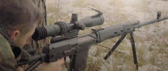
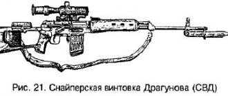
Disassembly and assembly of the 7.62 mm Dragunov sniper rifle (SVD)
5. use firearms;
6. ensure law and order;
U 7. maintain public order;
8. select and tactically correctly use special equipment in various operational and service situations and document this use;
9. correctly draw up and execute official documents, including secret ones containing restricted information;
10. perform official duties in strict accordance with the requirements of the secrecy regime;
know:
3 1. organizational and legal foundations and tactics of the activities of law enforcement officers in special conditions, emergency circumstances, emergencies, during a state of emergency and in wartime; tasks of law enforcement agencies in the civil defense system and in the unified state system for the prevention and response to emergency situations
3. basics of engineering and topographical training; legal basis, conditions and limits of the use and use of firearms by law enforcement officers;
3. main types of weapons used by law enforcement officers;
3 4. safety measures when handling firearms;
3 5. purpose, combat properties, design, rules for saving service weapons, as well as rules for handling and maintaining them;
3 6. tactics of individual and group actions in the process of performing operational and service tasks with the use and use of weapons;
3 7. organizational, legal and tactical foundations for ensuring law and order, protecting public order;
3 8. purpose, tasks, technical capabilities, organizational and legal basis and tactical features of the use of various types of special equipment and technical means;
9. established procedure for organizing office work, using information contained in documents;
3 10. basic rules and procedure for preparing and processing documents;
3 11. organizational and legal foundations of the secrecy regime in law enforcement agencies, the procedure for classifying information as a state secret, the procedure for classifying and declassifying carriers of information constituting a state secret, the procedure for access to state secrets;
3 12. Rules for the use and handling of secret documents and products.
In the classroom, ICT is used to control knowledge and skills and optimize the educational process.
This methodological development is intended for teachers of disciplines of the professional cycle, working in groups of secondary vocational education, implementing the requirements of the Federal State Educational Standard in the implementation of basic professional educational programs to the level of graduate training in specialty 40.02.02 “Law Enforcement.”
The procedure for assembling a sniper rifle after partial disassembly.
1) Attach the gas piston and pusher with spring.
Place the spring on the rear end of the pusher; insert the front end of the pusher into the gas tube, tighten the spring and insert the rear end of the pusher with the spring into the channel of the aiming block; pull the pusher back and move its front end out of the gas tube to the side; insert the gas piston into the gas tube, and the front end of the pusher into the piston socket.
2) Attach the barrel linings.
Insert the rear (widened) end of the right (left) barrel lining into the lower thrust ring with the cutout of the lining towards the sight and, pressing the lining down, attach it to the barrel; push the moving part of the upper thrust ring onto the tips of the linings and turn the closure of the upper thrust ring towards the gas tube until its bend enters the cutout on the ring.
3) Attach the firing mechanism.
Place the cutouts of the trigger mechanism housing behind the axis of the receiver jumper and press the trigger mechanism to the receiver; insert the fuse axis into the hole in the receiver; Turn the fuse to a vertical position, press it tightly to the receiver and turn down until the protrusion of the shield enters the lower locking recess of the receiver.
4) Attach the bolt to the bolt frame.
Insert the bolt with the cylindrical part into the channel of the bolt frame; turn the bolt so that its leading protrusion fits into the figured cutout of the bolt frame, and push the bolt forward as far as it will go.
5) Attach the bolt carrier to the bolt.
While holding the bolt in the forward position, insert the guide protrusions of the bolt frame into the cutouts of the receiver bends, press the bolt frame against the receiver with a slight force and push it forward.
6) Attach the receiver cover with the return mechanism.
Insert the return mechanism into the bolt frame channel; compressing the return springs, insert the protrusions on the front end of the cover into the cutouts on the lower thrust ring; press the rear end of the cover until it is completely adjacent to the receiver; Turn the receiver cover lock forward until it engages the lock.
7) Attach the butt cheek.
Place the cheekpiece on the top of the butt with the clasp to the right opposite the cutout for it; put the loop on the hook of the clip and turn the clasp up.
Attach the optical sight.
Align the grooves on the sight bracket with the protrusions on the left wall of the receiver; push the sight forward as far as it will go and tighten the clamping screw handle toward the lens until its bend fits into the cutout on the bracket.
9) Attach a store.
Insert the magazine hook into the receiver window and turn the magazine towards you so that the latch jumps over the magazine support ledge.
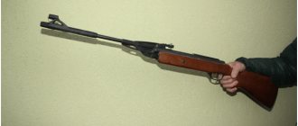
General information about IZH-61
The bottom line is this: this is a cheap spring-piston rifle, for which craftsmen have already developed a ton of upgrade options. It shoots small bullets of 4.5 mm caliber, or otherwise designated as cal .177, you can’t shoot balls from it!
What is also interesting about the rifle is the variety of appearance that the tuners strive for: here is the VSS, and the AK-47, and in general, anything else. Feel like a stalker))
The bullet speed is approximately 130 m/s, the rifle power is up to 7.5 Joules.
As of June 2014, the cost of the IZH-61 rifle is approximately 3,500 - 4,500 rubles. depending on the store. In my native Cherepovets, I bought it in the Kombat store on Parkovaya, 7 (it’s behind the church, not far from the beach). In general, in our local stores the price tag looks like this: “Robinson” - 4,800, “Weapon” - 4,530, “Combat” - 4,200, “Khaki” - no, “Soldier of Fortune” - no.
This rifle out of the box is practically not intended for anything other than training. Shooting at living creatures (such as crows, pigeons, etc.) will most likely lead to wounded birds and animals suffering from the new “hunter”, since the power of the rifle is not enough to guarantee the killing of a bird or animal.
The procedure for completely disassembling a sniper rifle.
1) Carry out partial disassembly
, guided by Art. 6.
2) Disassemble the store.
Using a drift, press the protrusion of the locking bar into the hole on the magazine cover and move the cover slightly forward; holding the locking bar with your thumb (Fig. 12), remove the cover from the body; Gradually releasing the spring, remove it together with the locking bar from the magazine body, and then separate the feeder.
Rice. 12. Magazine lid compartment
3) Disassemble the return mechanism.
Press the spring lock of the earring axis and use a drift inserted through the hole in the right wall of the receiver cover to push out the earring axis (Fig. 13, a); turn the return mechanism up to a vertical position and remove the earring from the lid liner window (Fig. 13, b); put the guide sleeve on the ramrod link, place it vertically on a table or stop and compress the rear return spring so that its end comes out of the cup of the shackle, move the shackle and disengage it from the protrusion of the guide rod (Fig. 13, c) separate the return springs and the rod from the guide bushing.
Rice. 13. Disassembling the return mechanism:
a - pushing out the axis of the earring; 6 – compartment of the return mechanism; c – earring compartment
4) Disassemble the shutter.
Push out the pin holding the firing pin with a punch and remove the firing pin from the bolt channel, push out the ejector axis with a punch (Fig. 14) and remove the ejector with the spring from the bolt.
Rice. 14. Pushing out the ejector shaft
5) Disassemble the trigger mechanism.
Press the self-timer lever and disconnect the self-timer sear from the ejector axis with the trigger; holding the trigger with your thumb, press the trigger (Fig. 15) and smoothly release the hammer; remove the ends of the trigger spring from under the hooks of the trigger mechanism housing; using a screwdriver, align the protrusions of the trigger, sear and self-timer axes with the cutouts for them on the right wall of the trigger mechanism housing; push out the trigger axis and separate the trigger with the spring; push out the sear axis and separate the sear; push out the self-timer axis and separate the self-timer; push out the hammer axle with a drift, separate the hammer with the mainspring, and then remove the mainspring from the hammer trunnions.
Rice. 15. Holding the trigger when decocking it
6) Separate the gas pipe from the regulator.
Turn the regulator (see Fig. 23) until the cutout on its front part aligns with the protrusion of the gas tube latch, press the latch with your finger and use the pencil case key to unscrew the gas tube (Fig. 16), and then remove the regulator from it.
Rice. 16. Gas tube compartment
Bullets for IZH-61
3. You need bullets. The bullets cost me about 250 rubles. per package. I took GAMO Master Point and GAMO Hunter. Why are they like this? Firstly, some are pointed, others are blunt - I’ll see what the difference is, and secondly - what difference does it make which one to take for the first time...
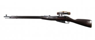
Self-loading rifle Tokarev SVT-40. Complete disassembly and reassembly
Detailed detailed demonstration of complete disassembly and assembly of the SVT-40 (AVT-40) rifle. Complete disassembly of the Tokarev SVT-40 rifle Complete disassembly of the rifle is carried out in the following order: 1. The magazine is separated. - take the rifle in your left hand; — with your right hand, lower the tail of the latch down; - grab the magazine and, pressing the latch with your thumb, separate the magazine from the receiver, turning it forward. 2. The receiver cover is separated. - press the tail of the latch upward; — place the rifle on the table with the sight up so that the bracket rests against the edge of the table; — with your left hand, push the lid forward by the back until it stops; — rest the thumb of your right hand on the head of the guide rod, without touching the cover, and, lifting the front end of the cover up, separate it from the receiver; - Carefully release the return spring until the head of the rod stops against the rear wall of the receiver. 3. The return spring is separated. — with your left hand, take the spring near the bolt stem and send it back until the guide sleeve exits the bolt stem socket; - holding the guide rod with your right hand, move its rear end away from the rear wall of the receiver and remove the spring from the bolt stem; - remove the spring from the guide sleeve, and if necessary, then from the rod. 4. The shutter is separated. - move the bolt stem back so much that the guide protrusion on its right side comes out of the groove of the receiver; - turning the handle and lifting the right wall of the bolt stem, push the bolt stem all the way forward; - lifting the bolt stem up by the handle, separate it from the receiver. 5. The frame of the shutter is separated from the stem. — place the stem of the bolt on the palm of your right hand with the handle forward and the body of the bolt up; - with the thumb and index finger of your left hand, take the bolt frame and push it back until it stops; — lifting the rear end of the shutter frame up, move it forward and separate it from the stem. 6. The cleaning rod is separated. To do this, you need to press the head of the ramrod latch and, lifting the ramrod up, pull it out of the stock socket. 7. The trigger mechanism is separated. — place the rifle on the table with the sight up; — with the thumb of your right hand, turn the bushing locking flag to the left by 90°; - press the rear cut of the receiver bushing with a drift and move it forward so much that the latch tooth comes out of the cutout of the trigger guard; — with your left hand, move the rear end of the trigger guard down, shifting it toward you, and separate the guard from the receiver. 8. The stock ring is separated. To do this, you need to place the rifle vertically, press the ring latch with a drift, sinking its tooth into the cutout, move the stock ring up and remove it from the barrel. 9. The upper casing is separated. To do this, lift the rear end of the casing up with your right hand and, moving it back, separate it from the barrel. 10. The receiver lining is separated. — with your right hand, take the barrel lining by the middle part; — lifting the middle end of the barrel lining up, push it forward until the rear end comes out from under the sight block and separate it from the barrel. 11. The barrel is separated from the stock. — put the rifle with the head of the dowel bolt up; - use a wrench to unscrew the dowel bolt and use a drift to knock it out of the tube; - turn the rifle with the sight up and, holding it with your left hand, separate the barrel from the stock with your right. 12. The gas piston, rod and bolt stem pusher are separated. — place the barrel with the sight up, holding the gas piston on the tube with your left hand; — with your right hand, push the rod back until it stops, move its front end slightly to the side; — remove the gas piston from the pipe with your left hand; — pushing the rod forward with your right hand, remove the bolt pusher from its socket; - remove the bolt pusher with the spring forward from the receiver hole (if it did not come out together with the rod); — remove the spring from the bolt pusher. 13. The gas regulator and pipe are separated. — place the barrel with the sight up and the muzzle towards you; — holding the barrel by the muzzle with your left hand, unscrew the pipe with your right hand using a key, rotating it from left to right; - Use a hammer to push the regulator out of the gas chamber socket. 14. The firing pin is separated from the bolt. To do this, use a drift to push the firing pin out of the hole in the bolt frame and push the firing pin together with the spring out of the bolt socket. Assembling the SVT-40 rifle: Assembly is carried out in the following order: 1. The regulator and pipe are installed. — place the barrel with the sight up; — insert the regulator into the gas chamber socket with the pentagon facing forward; — set the edge of the regulator with the appropriate number upward so that this edge is horizontal; - screw the pipe all the way, first by hand and then using a wrench; — Check again that the top edge of the regulator is horizontal. 2. The gas piston, rod and pusher are assembled. — put the spring on the pusher; — insert the rear end of the rod into the pusher socket; — with your right hand, insert the rod with the pusher and the spring into the hole in the receiver; — push the rod all the way back, move its front end to the side, and put the gas piston onto the pipe with your left hand; — insert the front end of the rod into the piston socket. 3. The barrel is attached to the stock. - holding the barrel with your right hand by the receiver, with your left hand - insert the front end of the casing into the bell of the muzzle; — insert the receiver into the box window; - place the rifle on the left side on the table and, inserting the dowel bolt on the right side, use a wrench to screw it in until it stops. 4. The receiver lining is put on. — put the rifle with the sight up, holding it with your left hand by the neck of the butt; — with your right hand, lifting the front end of the receiver lining slightly upward, place the rear end behind the protrusion of the sight block and press the receiver lining to the barrel. 5. The upper casing is put on. To do this, you need to insert the bends of the front end of the casing into the grooves of the lower casing with your right hand and lower the rear end of the casing onto the front end of the receiver lining. 6. The stock ring is put on. - place the rifle vertically; — put the ring on the stock with the slot for the belt to the left; — recess the latch tooth into the cutout of the stock; — push the ring down until the latch tooth slides past the front edge of the ring. 7. The cleaning rod is inserted. — press the ramrod latch; — insert the front end of the cleaning rod into the hole in the muzzle protrusion; — move the cleaning rod down so that the latch tooth is above the protrusion on the cleaning rod rod; — release the cleaning rod latch. 8. The trigger mechanism is inserted. — check the position of the receiver bushing locking flag, which should be turned to the left; - turn the rifle aiming down; — insert the trunnions of the front end of the trigger guard into the cutouts of the receiver; - press the rear end of the trigger guard and with an energetic push of the palm of your right hand, push the trigger guard into the cutout of the stock. In this case, the latch tooth should pop into the bracket cutout, and the rear wall of the receiver bushing should come close to the rear wall of the receiver; - turn the rifle with the sight up, lower the flag down, turning it from left to right. 9. The firing pin is connected to the bolt frame. — put the spring on the hammer; — insert the firing pin with the spring into the bolt channel; — align the cutout of the striker with the hole for the pin and insert the pin. 10. The bolt frame is connected to the stem. - take the bolt stem in your right hand with the cutout facing upward, handle forward; — with your left hand, insert the front end of the bolt frame into the cutout of the stem, move the bolt frame all the way back and insert its protrusions into the cutouts of the stem. 11. The bolt is inserted into the receiver. - hold the rifle by the neck of the butt with your left hand; — with your right hand, insert the guide protrusion of the bolt stem into the groove of the receiver; — move the bolt stem back until its guide protrusion aligns with the cutout of the receiver; - turn the bolt stem down by the handle and push it forward as far as it will go. 12. The return spring is inserted. — put the spring on the guide tube and rod; — with your right hand, insert the end of the spring forward into the socket of the bolt stem; - with your left hand, take the spring near the rear end of the guide tube and insert the latter into the socket of the stem; — with your right hand, place the head of the guide rod behind the rear wall of the receiver, while directing its front end into the tube channel. 13. The receiver cover is inserted. — put the rifle with the sight up; — put the cover on the stem of the shutter; — with your left hand, move the spring guide rod slightly forward; — press the head of the rod with the thumb of your right hand and push it forward until it stops; - take the lid with your left hand, insert the head into the semicircular cutout of the lid and, holding the lid with your left hand, push it back. 14. The magazine is inserted. — place the protrusion of the front wall of the magazine behind the ledge of the receiver; — turning the magazine, feed it into the receiver window. The magazine latch should slide over the transverse projection of the rear wall of the magazine; — turn the tail of the latch towards the receiver.
Disassembly
the rubber pads on the sides (29500, 29250) have grooves for a flat-head screwdriver on the butt side. Remove the pads and unscrew the fastening screws, one on each side and one next to the trigger (16350, 02660). Don’t lose the screws and washers 12200; take out all the iron and set the stock aside. Don’t lose spare parts 04852, 15050, unscrew screw 16190, which secures the trigger and into which fastening screw 02660 is screwed in, look at the trigger, the bar from the cocking lever fits into it, find the mounting location on the trigger, remove it, and don’t forget to disconnect the spring. Do not lose spare parts 14300, 16080, rest the iron with its back side on the floor and knock out pin 12530 using a nail (metal rod) and a hammer, remove the rear plug with guide 16272, the plastic attachment 16320 and the spring.0 remove the trigger by moving it towards the butt and then up remove piston 15278. Do not damage the cuff! clean all conservation lubricant with the trigger, wipe with alcohol, lubricate