Mi-8 helicopter
(product “80”, B8, NATO designation:
Hip
) - Russian multi-purpose helicopter, produced by
OKB M.L.
Mile in more than 30 military and civilian modifications. The Mi-8 helicopter made its first flight in June 1961. Holds the record for the number of modifications.
In terms of weight category, the Mil Mi-8 belongs to category I helicopters. made according to a single-rotor design with a 5-bladed main rotor and 3-bladed tail rotor. By the way, Mil OKB began to assemble the first combat training helicopter.
Schemes of the Mi-8 - multi-purpose transport helicopter
The power plant of the Mi-8 helicopter is controlled by the pilot moving the command levers in the cockpit.
The pilot can carry out control actions as follows: 1) By moving the “Step-throttle” (RSG) handle (Fig. 10.1, item 1) up (down). This leads to an increase (decrease) in the power of both engines and an increase (decrease) in the installation angles of the rotor blades.
2) Rotate the correction handle (RK) 17
relative to the pilot to the right (left). This leads to an increase (decrease) in the power of both engines without changing the angles of the rotor blades.
Rice. 10.1. Integrated control system "Step-Gas":
1 — “Step-throttle” handles;
2 — levers for separate engine control;
3 , 6 , 10 — engine control rods;
4 - closing shaft; 5 , 11 — control rods for the main rotor pitch; 7 —rods for separate engine control; 9 — differential unit; 12 — shaft block; 13 — control unit; 14 — hydraulic booster for controlling the collective pitch of the NV; 15 — lever for controlling the overall pitch of the NV; 16 — control levers HP-40; 17 — correction handle
.
3) By moving the right (left) lever for separate engine control (RRD) 2
from its neutral position up (down). This leads to an increase (decrease) in the power of only the right (left) engine without changing the installation angles of the main rotor blades.
Separate engine control levers are used when testing engines separately on the ground and when flying with one engine failed. In this manual, this case of operation of the power plant control system will not be considered. In the future, we will assume that the separate control levers are in the neutral position.
4) By moving the engine stop control handles (ESC) (Fig. 10.2, pos. 1) relative to the pilot away from you (towards you), it leads to the closing (opening) of the stop valve of the HP-40 pump-regulator (Fig. 7.6, pos. 59 ,60).
Movement of the RShG, RC, RRUD leads to a change in the position of the control lever (RU) (Fig. 7.6, pos. 15) on the NR-40 pump-regulator. This changes the tension of the spring 11
speed controller, which leads to a change in engine operating mode.
Rice. 10.2. Engine stop control system diagram:
1 - handle;
2 , 11 — bracket; 3 - bolt; 4 — fastening of cables on rollers;
5 — cable stop;
6 , 10 - rollers; 7 — cables; 8 — levers of the stop valve of the fuel pump-regulator HP-40; 9 — thrust; 12 — tenders; 13 — driver
Control of engine operating modes is carried out by HP-40 and PO-40 units.
The HP-40 pump-regulator ensures maintenance or the required change in the turbocharger rotor speed (ntk). The HP-40 tuning characteristic is determined by the cam profile (Fig. 7.6, pos. 14) and is shown in Fig. 10.3. Participation "A-B" characteristics when turning the control lever 15
To increase the engine operating mode, the regulator cam increases the tension of the pendulum spring. The regulator pump is adjusted to increase the fuel supply. In the “B-C” section, the regulator cam contacts the control lever along a surface with a maximum and constant radius. In this case, the tension of the pendulum spring is maximum and unchanged. The regulator is configured to maintain maximum and constant turbocharger speed.
Rice. 10.3. Adjustment characteristic of pump-regulator HP-40 (H=0,V=0):
α p.y. — position of the control lever (RU) HP-40,
nt.k. ass — specified (tuning) rotation speed of the turbocharger rotor.
The RO-40 speed controller limits the rotation speed of the free turbine rotor, and therefore the main rotor. The limitation is ensured by reducing the fuel supply to the combustion chamber. In this case, in all engine operating modes the following condition is met:
where ns.t. — rotational speed of the free engine turbine,
ns.t, rear — maximum permissible (specified) free turbine rotation speed.
For TV2-117 engine. ns.t, set is determined by the setting of the RO-40 regulator and is equal to 95 ± 2%
A schematic diagram of the control system for the power plant of the Mi-8 helicopter is shown in Fig. 10.4.
Rice. 10.4. Schematic diagram of the power plant control system
RShG - "Step-gas" handle,
RK - correction handle,
RRUD - separate engine control levers,
RU - control lever for pump-regulator HP-40,
AP - swashplate,
RSK - stop valve lever on the HP-40 pump-regulator,
RUOD - engine stop control handle.
nt.k is the rotation speed of the turbocharger rotor,
ns.t. — rotation speed of the free turbine,
ϕ B is the angle of installation of the main rotor blades,
Gfuel —fuel consumption.
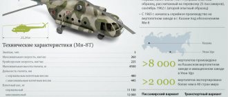
Specifications
The length of the Mi-8AMTSh helicopter is more than 18 m. Its height is 5.65 m. The main rotor in diameter is 21.29 m, and the additional (tail) is 3.91 m. The empty helicopter weighs 7.26 tons. Take-off normal weight is 11.1 tons, maximum weight is 12.2 tons.
Earlier models were equipped with two turboshaft engines with a take-off power of 2100 hp. With. Models produced after 2014 began to be equipped with two engines with a reinforced transmission.
The helicopter's speed can be up to 260 km/h. Cruising speed is 225 km/h. The fuel tank holds 1450 kg of fuel. It can be further expanded by a further 1420 kg. At the same time, the practical range of the vehicle is 1200 km. But the range is 465 km.
The crew consists of only 2 people.
Mi-8 helicopter. First tests. Characteristics. Photo. Video.
The Mi-8 is a multi-purpose and widely used helicopter. Designed and developed by OKB designers M.L. Mile in the early 60s. This Soviet development is the most popular twin-engine air transport vehicle in the world (it is on the list of the most common helicopters in the world history of aviation). It has two directions: military and civil.
In July 1961, the B-8 prototype took off for its first flight. A year later, the second copy of the B-8A was released. In 1967, the Mi-8, which had already been fully modified and changed its old name to a new one, entered service with the Air Force of the Soviet Union. Since the model has proven to be one of the most successful, the current Russian Air Force is also ordering this helicopter. At the moment, this unit is used in fifty countries around the world.
Mi-8 design
The Mi-8 is a single-rotor helicopter equipped with five main rotors and three tail rotors. The main rotors are fixed by vertical, horizontal and axial hinges, and the steering blades, respectively, are of a combined cardan type. The transmission is exactly the same as that of the Mi-4. The all-metal propeller blades include a hollow spar pressed from an aluminum alloy. Attached to its rear stern are 24 compartments with a honeycomb filling made of aluminum foil (forming a profile). The main rotor blades are equipped with an alarm for possible damage to the spar.
An improved antifreeze system prevents the helicopter from becoming icy. It is electrified and has the ability to work in both autonomous and manual modes (feeding 208 volts). In the event that one of the engines fails, the other automatically increases its power. And it does not affect horizontal flight and altitude. Three KAU-30B hydraulic boosters provide high-quality control of the main rotor, and RA-60B steering boosters.
The three-wheel landing gear cannot be retracted. The tail support prevents the tail rotor from touching the ground. Thanks to the external suspension system, the helicopter can transport cargo weighing up to three thousand kilograms. Stabilization of roll, direction, pitch and flight altitude is provided by a four-channel autopilot AP-34.
The passenger version can accommodate up to 18 seats, and the transport version can accommodate 24 seats. The internal climate, heat and cold support are controlled by a KO-50 (kerosene heater) and a specially designed ventilation system. Thanks to navigation instruments and radio equipment, the Mi-8 can fly regardless of weather conditions and time of day.
Depending on the methods of application, there is a huge difference between the modifications. One of the first Mi-8s took off thanks to two TV2-117 engines. Their power was 1500 hp, and the 10-stage compressor was started from the GS-18TO starter-generator. Starting the starter-generator of the first engine is powered by six 12CAM28 24 V batteries, and the second is powered by the starter-generator of an already running engine.
During operation of the GS-18TO engines, a voltage of 27 V is supplied to the main power supply system. Two batteries are installed in the cargo compartment, and the remaining four are mounted in the pilot's cabin. Although their capacity is small, it still does not interfere with powering five engine starts in turn. They deliver current in excess of 600-800 amperes, while being charged from generators (direct current) and can automatically turn on and off. This ability is made possible thanks to differential minimum relays (control of generator operation).
The PT-500Ts converter powers gyroscopic devices with a three-phase voltage of 36 volts. The SGO-30U generator supplies single-phase current (208 V) to the heating elements of windshields and propellers. Two single-phase transformers TS/1-2 and Tr-115/36 depart from SGO-30U. The first powers navigation equipment, and the second powers transmission and engine control devices. In case of malfunctions and failure of the SGO-30U, all equipment switches offline to the PO-750A converter.
Later series Mi-8MT, Mi-17 and others differ significantly from the base model. The installed TV3-117 engines are much more powerful. The air supply to the starters is provided by the AI-9V APU and the STG-3 starter generator. The power supply system produces a voltage of 208 V with a frequency of 400 Hz. It is powered by SGS-40PU generators, which are located on the main gearbox. To start the APU and in case of emergency power supply, 12SAM-28 batteries are installed.
The main power supply is provided by three VU-6A rectifier devices. The first generator is responsible for supplying current to VU No. 1, heating elements of the transformer and propellers, and the second powers VU No. 2 and No. 3, the glass heating mechanism and the ROM of the engines. In some modifications, the TS/1-2 transformer is additionally heated.
If one generator fails, the TS310S04B switches to the second; if both fail, then the PT-200Ts and PO-500A converters are started.
The helicopter is equipped with two hydraulic systems: the main one and the backup one. The NSh-39M pump installed on the main gearbox creates pressure in each of them. Its adjustment occurs with special automatic machines GA-77V. The main system is supported by two hydraulic accumulators, and the backup system by one. Separate electromagnetic valves GA192 include hydraulic power supply for RA-60B, KAU-30B of the common main rotor and two KAU-30B controls of in-line and transverse types.
There are many types of modernization of the Mi-8. They are divided into types:
1. Experienced
V-8 - the first experimental helicopter with one installed AI-24V gas turbine engine;
Helicopter development.
In 1960, OKB Mil M.L. began developing a new transport helicopter that would replace the outdated Mi-4. An experimental prototype designated B-8 made its first flight in June 1961. The helicopter was equipped with one AI-24 gas turbine engine and a four-blade main rotor from the Mi-4. Later, the designers made a number of improvements. The power plant was replaced with two TB2-117 gas turbine engines. The main rotor became five-bladed.
Engine AI-24.
Production and release.
Flight tests began on September 17, 1962. The helicopter fully lived up to the expectations placed on it. Since 1965, it went into mass production under the designation Mi-8. The design of this machine turned out to be so successful that its production and modernization continue to this day. Today the Mi-8 is one of the most common transport helicopters in the world. More than 8,000 cars were produced in various modifications. The helicopter is operated in more than 50 countries around the world.
Mi-8 cabin
By its design, the Mi-8 is a single-rotor helicopter. The fuselage is a semi-monocoque frame consisting of a cockpit, a cargo compartment and a tail boom. The cockpit is three-seater, designed for two pilots and a flight mechanic. The cargo compartment can be adapted for transporting cargo or equipped with seats for passengers. In the transport version, loading is carried out through a double-leaf cargo hatch. The landing gear is tricycle non-retractable. The power plant consists of two gas turbine engines TV2-117A (TV3-117MT), 2x1710 (2x3065) hp. The main rotor is five-blade with all-metal blades. The tail rotor is three-bladed.
Engine TV2-117A.
Helicopter modifications.
There are more than 30 modifications of this vehicle, the main ones being the Mi-8T (transport) and Mi-8P (passenger). The Mi-8AMTSh is an air assault variant with missile and machine gun armament. The helicopter is used to perform a wide range of missions, both in civil aviation and in the air force. Since the 70s, the Mi-8 has been used in many military conflicts in different parts of the world.
Mi-8P (passenger).
Mi-8T (transport).
Protection system and armor
The Mi-8AMTSh differs from its predecessor in improved armor. Its protection is made of ceramic-metal armor. Thanks to this, the crew and main parts of the vehicle are protected from 12.7 mm bullets. As for fuel tanks, if they are hit, a special protective system will fill the hole with polyurethane foam. Thanks to this, fuel loss is eliminated.
The crew has 2 standard parachutes, which are necessary for evacuation in case of damage to the vehicle. They are used if the helicopter is at an altitude of more than 100 m. If the altitude is less than this value, then the impact is compensated by a special design of the landing gear (to a greater extent) and seats (which compensate for the remaining impact).
History of the creation of the Mi-8 helicopter
With the advent of the Mi-6 heavy helicopter, a new era in helicopter construction opened. However, a heavyweight was not needed everywhere and not always; a “medium” helicopter, like the Mi-4, was much more in demand, but the latter no longer met the requirements of the time.
On February 20, 1958, a Decree of the Council of Ministers of the USSR was issued ordering the development of a new helicopter to replace it, not with a piston engine, but with a gas turbine engine. The working name of the new helicopter was V-8, but it went down in history as the Mi-8 multi-purpose helicopter . The new vehicle was to be designed in two versions at once: the passenger Mi-8P and the transport Mi-8T.
Purpose
The Mi-8AMTSh helicopter, which is unofficially called the “Terminator”, is used to transport personnel and cargo. Performs the following tasks:
- Landing of paratroopers (up to 26 people) in the rear or on the battlefield.
- Air cover for troops.
- Air reconnaissance of enemy positions.
- The ability to destroy tanks and other heavy equipment.
- Transportation of cargo (including ammunition) with a total weight of up to 4 tons.
- Transportation of the wounded on stretchers (12 seats in total) and accompanying doctors.
In addition, it is the Mi-8AMTSh that takes part in many rescue operations. It is capable of delivering airborne troops to the battlefield along with weapons, and taking the sick and wounded back.