The General Dynamics F-111 long-range tactical bomber was the world's first production aircraft to incorporate the variable-angle wing concept. At maximum angle, the wings were practically adjacent to the tail stabilizer. There was a gap of 250 mm between the trailing edge of the wing and the leading edge of the tail.
The machine did not have an official name throughout its service life, and only in 1996 it began to be called Aardvark (anteater). The assignment of the name occurred at the time the F-111 aircraft was removed from service. Due to the high cost, the aircraft was practically not exported. Apart from the US Air Force, the vehicle was used only by Australia, where it was unofficially designated Pig (pig).
History of creation
In the late 50s, the US Air Force realized the need to create a replacement for the F-105 fighter-bomber that was in service. The requirements for the new aircraft were extremely contradictory - the aircraft had to carry a large bomb load and have a speed corresponding to a fighter.
Moreover, the military’s demands were constantly growing. As requirements changed, applicants for the order were eliminated. By 1962, only Boeing and General Dynamics were vying for production.
The initial design of the future F-111 aircraft was equipped with a fixed wing, but to ensure speed parameters, a variable-sweep wing was best suited, which was implemented on the aircraft. The use of such a scheme led to an increase in the cost of the aircraft and scared off a number of potential customers.
A novelty for its time was a radar station for monitoring the terrain.
Flying in this mode significantly reduced the likelihood of being hit by anti-aircraft fire. This continued until the advent of new types of weapons adapted to defeat air targets flying in terrain repeat mode.
The F-111A prototype flew in 1964, and mass production began three years later. Due to the high cost and problems with matching the profiles of the air intakes and the power plant, the volume of orders for the F-111A has decreased.
Vehicles of various modifications were used by the US Air Force until 1996. Australian vehicles lived longer - they were removed from service only in 2010. Some early American aircraft were converted into electronic warfare vehicles under the designation EF-111A. A total of 42 such aircraft were built.
Pe-2 - the most popular bomber
Pe-2 in the sky.
In 1938, the famous Tupolev “sharazhka” began developing the Pe-2 dive bomber, which later became the most popular Soviet bomber of the Great Patriotic War.
The Pe-2 was very compact and had an all-metal structure with good aerodynamic shape. The bomber was equipped with 2 liquid-cooled M-105R engines of 1100 hp each, which allowed the aircraft to reach speeds of up to 540 km/h (only 30 km/h less than the Me-109E fighter, which was in service with the Nazi army ).
The legendary Soviet bomber Pe-2.
In 1940, 2 serial bombers were produced, and at the beginning of 1941, 258 Pe-2 bombers rolled off the production line. On May 1, 1941, a new bomber, which received the 95th Air Regiment under Colonel Pestov, flew during a parade over Red Square. Pe-2s took part in hostilities literally in the first days of the war. By 1943, Pe-2 bombers ranked first in number in bomber aviation. Thanks to their high bombing accuracy, they were very effective weapons. It is a known fact that on July 16, 1943, the pilots of the 3rd Bomber Air Corps, in their 115 aircraft, destroyed 229 vehicles, 55 tanks, 12 machine gun and mortar points, 11 anti-aircraft and 3 field guns, 7 fuel and ammunition depots.
In the cockpit of the Pe-2.
And although in 1944 Tu-2s began to arrive at the front, which were superior to the Pe-2 in their main parameters, the “pawn” remained the main Soviet bomber until the end of the war and, together with the “maize”, became a legend of Soviet aviation.
Design
The fuselage of the F-111 fighter-bomber is built according to a semi-monocoque design with a T-shaped power beam, which is the load-bearing element for the power plant.
Aluminum, steel and titanium-based alloys are used in the design of the fuselage power kit.
Machined aluminum panels are exemplary for lining caisson fuel tanks. The remaining areas are covered with sandwich panels made of aluminum sheet and honeycomb core.
The F-111 variable-sweep wing has a power set consisting of four spars. Mechanization includes slats and flaps. The kinematics of the flaps allows their deflection within a certain range of sweep angles.
The deflection mechanisms of slats and flaps are interconnected. Brake flaps are installed on the upper plane of the wing. A characteristic feature of the F-111 aircraft was the blocking of the flaps when the sweep angle increased beyond 26°.
The wing sweep of the F-111 aircraft changes smoothly within the range of 16-72.5⁰. Additionally, there are four fixed positions for takeoff, landing, maximum and cruise speed.
The hinges connecting the rotating part to the fixed part are located inside the structure and practically do not disturb the flat surface of the skin. The F-111 wing drive is hydraulic and controlled by two systems that duplicate each other. The adjustment mechanism does not allow you to set an asymmetrical angle.
The chassis is equipped with a nose and two main struts.
The design of the racks allows the F-111 to be operated from unpaved airfields. There are two wheels installed on the nose strut; cleaning is carried out in the direction opposite to the flight.
The main pillars are retracted into niches made between the air intake housings of the power plant. The main struts of the F-111 aircraft are mounted on a single console and operate from a single hydraulic cylinder.
The niche flap is equipped with a special drive that allows the flap to be used as an additional air brake.
The cockpit on the F-111 aircraft is equipped with two seats installed in parallel. The instrument panels are asymmetrical, the right side of the board is used for navigation and radar equipment. On the left side there are flight equipment and indicators of the power plant operating parameters.
Access to the cabin is through flaps on the canopy. The cabin has a special shield that automatically rises during a nuclear explosion. The shield protects the crew from the light and thermal effects of the explosion.
The F-111's controls are equipped with hydraulic boosters. To eliminate vibrations that occur during flight, an automatic correction mechanism equipped with an electro-hydraulic drive is used.
If an emergency occurs on board, the F-111 cabin ejects.
A parachute is used to reduce speed. An additional shock absorber that softens the impact upon landing is a pneumatic rubber cylinder.
The balloon provides buoyancy to the cabin when landing on the water surface. Shooting of the cockpit is allowed at low altitude or when the F-111 is immersed in water to a depth of 15 meters.
The fuel supply on the F-111 aircraft was located in caisson tanks located in the moving part of the wing console, as well as in a separate keel tank and two additional tanks installed in the fuselage. The fuselage tanks are located in the middle part and in the tail above the power plant.
The tanks are capable of holding 19021...19052 liters of fuel (depending on the model). The tanks are refilled centrally through the neck located in the area of the left air intake.
The F-111 aircraft is equipped with an in-flight refueling system, which is carried out through a special boom. The boom is mounted on top of the aircraft behind the cockpit canopy.
To increase the flight range of the F-111, external fuel tanks were used, which were installed on six pylons under the wings. There were two types of tanks, differing in size and capacity (1700 and 2270 liters, respectively).
The power plant of the F-111 aircraft consists of a pair of Pratt & Whitney model TF-30P turbojet engines equipped with an afterburner.
Depending on the modification of the F-111 aircraft, the engines have a nominal thrust of up to 79.6 kN and a thrust of up to 112 kN in afterburner.
The engine is built on a two-shaft design. On one shaft there is a fan (depending on the modification, it has two or three impellers) and two compressors. The low-pressure compressor is equipped with six compression stages, the high-pressure compressor with seven stages.
On the second shaft there is a high-pressure (one stage) and low-pressure (three stages) turbine. In front of the turbine there is an annular combustion chamber. The afterburner can be adjusted, providing five modes of thrust change.
| Motor housing diameter, mm | 1245 |
| Total length, mm | 6139 |
| Weight, kg | 1807…1816 |
| Air pressure increase rate | 19,8…21,8 |
| Temperature of compressed air in front of the turbine, C° | 1124…1176 |
The spin-up of the compressor and turbines to start the first engine is carried out with compressed air supplied from a ground source. The second engine is started with compressed air taken from the compressor of the running engine. In the absence of a ground compressor, starting is performed with a powder starter.
The F-111 air intakes were equipped with control cones and devices for cutting off the boundary layer of air flow.
Generators are installed on the distribution boxes of turbojet engines. The F-111 aircraft uses two 60 kW generators. Hydraulic pumps are also installed on the boxes, feeding two separate hydraulic systems.
Electricity consumers were avionics equipment, which included three radar stations. The stations provided terrain-following flight in automatic and manual mode.
The F-111 control system includes an autopilot that operates based on data from on-board radars and a radio altimeter. The antennas are located in the forward part of the fuselage, covered by a fairing.
The F-111's armament is located inside the fuselage and on the pylons. The fuselage has a special compartment 4900 mm long, located between the installation points of the nose and main landing gear. Six pylons are installed on the wings. The pylons were divided into fixed (four external) and movable (two internal).
When setting the wing to a sweep above the minimum, the outer pylons were automatically disconnected from the plane. The inner ones rotated with the wing, ensuring parallelism to the flow and reducing drag.
The F-111's weapons are controlled by an on-board system equipped with an infrared direction finder and a target detection and tracking radar.
The pylons could accommodate aerial bombs of the M117A1 type weighing 340 kg, cluster bombs of the GBU-58 model, high-explosive aerial bombs Mk-82 or 83 (weighing 900 and 1350 kg, respectively). The F-111 bomber could carry laser-guided bombs as well as glide bombs.
The pylons made it possible to place Sidewinder-type guided missiles, which were used for self-defense. The fuselage compartment allowed the placement of atomic bombs or was used to install reconnaissance equipment. The F-111's additional armament was the M61 Vulcan six-barreled revolving cannon.
Modifications
The first production modification was the F-111A bomber, built in the amount of 160 copies. The first 30 vehicles were equipped with the TF30-P-1 power plant, the rest were equipped with the improved TF30-P-3 with increased traction. Several early vehicles did not have an ejection cockpit and were equipped with ejection seats.
For the needs of the fleet, a version of the F-111B fighter was built, largely unified with the land version.
The naval aircraft had a shortened nose section with the ability to tilt upward. This feature made it possible to place the vehicles on the flight decks and hangars of aircraft carriers.
Due to the more severe conditions of takeoff and landing, tires with increased operating pressure were used. The wing consoles were equipped with additional tips. The radar equipment installed on board varied greatly.
In total, from 4 to 7 F-111B aircraft were assembled. The customer refused to build the machines due to the significant excess weight (almost 9,000 kg).
By order of Australia, the F-111C variant was built, which is a combination of solutions from the F-111A fighter and the FB-111A strategic bomber. The aircraft was equipped with eight external weapon suspension points. The total weight of weapons could reach 14,300 kg.
In 1970, the modernized F-111D fighter-bomber appeared, equipped with improved engines and new on-board electronics.
A total of 96 cars of this version were assembled, which served until 1993.
Problems that arose during the fine-tuning of the electronics led to the creation of the F-111E version, which was an F-111A model with air intakes from modification D. General Dynamics Corporation built 94 aircraft of this model.
Due to the high cost of the new electronic equipment used on the F-111D, it was decided to create a simplified version under the designation F-111F. The aircraft were equipped with a new modification of the TF30-P-100 engine. A total of 106 vehicles were built.
Another option was the F-111G, built on the basis of airframes left over from the UK's refusal to purchase a batch of the F-111K (a special version for the United Kingdom).
On the basis of the fighter-bomber, the FB-111 strategic bomber was produced, which was distinguished by a fuselage extended by 640 mm, which made it possible to increase the fuel supply on board, and elongated wing consoles from the naval vehicle. A total of 77 vehicles were assembled, some of which were subsequently converted to the F-111G standard.
Performance characteristics in comparison with competitors
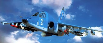
Due to its design, the F-111 has no direct competitors. The only aircraft with similar characteristics is the Soviet front-line bomber Su-24. Sometimes the Tu-22 bomber is compared to the F-111, but this comparison is not correct, since the Soviet machine is twice as large.
| Parameter | F-111E | Su-24M |
| Length, mm | 22 400 | 24 594 |
| Height, mm | 5 220 | 6 193 |
| Wingspan, mm | 19 200 | 17 638 |
| Empty weight, kg | 21 394 | 21 200 |
| Take-off weight, kg | 37 577 | 32 300 |
| Maximum weight, kg | 45 359 | 39 700 |
| Speed max., km/h | 2 655 | 1 700 |
| Ceiling, m | 17 985 | 11 000 |
| Rate of climb, m/s | 131,5 | No data |
| Crew, people | 2 | 2 |
The Su-24 bomber is equipped with unregulated air intake ducts and can only carry weapons externally.
The combat load of Soviet and American aircraft is approximately the same.
Tu-4 - the first Soviet strategic bomber
Tu-4 is the first Soviet strategic bomber.
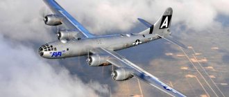
At the beginning of 1945, 4 American B-29 aircraft accidentally ended up at the Far Eastern airfields of the USSR, which took part in the bombing of Japan and the territories it occupied. When the Communist Party and the Soviet government gave the designers the task of creating a modern long-range bomber, MAI professor and aircraft designer Vladimir Myasishchev proposed copying American bombers, but installing domestic ASh-72 engines on the new aircraft, and replacing American machine guns with B-20 cannons.
Tu-4 clone B-29
The Tu-4, flight tests of which took place already in 1947, is an all-metal cantilever monoplane. The length of the bomber was 30.8 meters, and the wingspan was 43.05 meters. Four ASh-73TK engines with a power of 2400 hp. With. allowed the plane to accelerate to a speed of 558 km/h at an altitude of 10 km. Maximum bomb load is 8 tons. The efficiency of the aircraft was increased through the use of automation. For example, an onboard locator with an autopilot made it possible to find targets and hit them even at night.
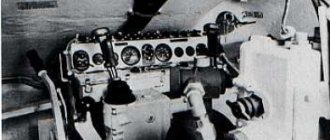
The cockpit of a Tu-4 bomber.
The Tu-4 became the first Soviet carrier of nuclear weapons when a bomber regiment armed with atomic bombs was formed in the USSR in 1951. In 1956, during the Hungarian events, the regiment flew a bombing mission to Budapest, which was interrupted at the last moment by order of the Soviet command.
A total of 847 aircraft were built, 25 of which were transferred to China.
Combat use
F-111 aircraft entered combat within a few months of being put into service. The first battlefield was Vietnam, where two or three vehicles were lost. Due to losses and identified problems with the wing folding mechanism, the aircraft were withdrawn from active combat operations.
The vehicles were re-entered into battle at the end of the Vietnam War. 54 aircraft took part in the battles, with losses amounting to 6 aircraft.
>In 1986, F-111F aircraft were used during a raid on the residence of M. Gaddafi (Libya).
The strike was carried out from air bases in Great Britain. As a result of the attack, two aircraft were lost (one made an emergency landing, the second went missing).
The second major combat episode in the F-111's career was Operation Desert Storm. It involved 20 Model E vehicles, which were used to drop unguided bombs. There are no official data on losses.
More advanced F-111Fs, equipped with guided weapons, were used more actively and completed 2,500 combat missions. According to official data, five planes were shot down.
Interesting facts and traces in history
Over the years of operation, out of 563 F-111 aircraft built, 123 aircraft were lost.
Initial calculations showed the cost of the F-111 in the region of 3.7 million dollars per copy. Constant improvements and improvements led to an increase in the development budget to $2 billion.
The first deliveries began at a price of $18.7 million per aircraft, which led to a reduction in production plans by three times.
The F-111 development program was the largest since the end of World War II.
The F-111, despite its rather controversial career, became a springboard for the creation of a more advanced F-14 Tomcat with a variable geometry wing. However, the successor did not gain much fame - out of 712 cars built, at least 166 copies were destroyed in accidents.
Il-28 - the first Soviet jet bomber
Il-28 at the airfield.
The design of the Il-28 bomber began with the tail. The fact is that the creation of this aircraft became possible thanks to the launch into mass production of a reliable English turbojet engine with a Nin centrifugal compressor, which used a defensive mobile installation, which determined the main layout features of the Il-28.
IL-28 in the sky.
The main advantage of the aircraft was the fact that the Il-28 was stable over the entire speed range. It easily performed any maneuvers necessary for bombers, performing turns with a roll of up to 80 degrees. During a combat turn, the altitude gain reached 2 km.
View from the cockpit of the Il-28.
Il-28 was produced under license in China under the name H-5. The aircraft was widely used in more than 20 countries. In total, about 6 thousand units were produced.
