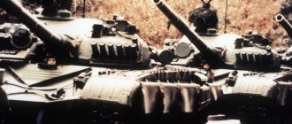
Home → Articles → Technology and equipment
An engineering clearing vehicle is a specialized military equipment whose main purpose is to lay column tracks, eliminate rubble and congestion at bombing sites, and other similar actions. For this purpose, the machine is equipped with a multifunctional bulldozer mechanism and a telescopic manipulator boom.
Technical characteristics of IMR-
Initially, the IMR was made on the basis of the T-55 tank. To perform its main tasks, the IMR is equipped with a multifunctional bulldozer blade and a manipulator boom. The IMR is hermetically sealed, which makes it possible to move underwater, descending to a depth of five meters (for this, a special underwater driving device is installed). In addition, the IMR has anti-radiation protection, thanks to which the equipment can be used in areas with increased radiation and contaminated with chemically aggressive substances. It is worth noting that the crew of the vehicle does without radiation protection.
Bulldozer equipment can be located in 3 positions: two-blade, bulldozer and grader. Changing the position of the cutting knife is carried out using a hydraulic device. In the two-blade position, IMR-2 can lay column tracks by throwing away obstacles (small rubble, snow, trees, etc.) on both sides of the moving vehicle. Other military equipment can follow along the cleared road.
In the bulldozer position of the shovel, the engineering clearing machine can cut off slopes, clear pits, make passages through ditches, etc. The placement of the shovel in the grader position involves clearing passage paths for various types of equipment.
To remove large and heavy objects from the path, the machine is equipped with a telescopic boom, on which it is possible to attach a bucket to use the equipment as an excavator. The first engineering clearing vehicles entered the armed forces in 1969. In general, 1,271 IMRs based on the T-55 tank were produced. Subsequently, modified engineering clearing vehicles were produced - IMR-2, IMR-3.
Modifications of engineering barrier vehicles
- IMR-2. The main vehicle for the IMR-2 clearing vehicle was the T-72 tank. These engineering vehicles entered service with the troops in 1980. In addition to the fact that they had the equipment used on the IMR-1, devices intended for mine clearance were added (the KMT-6 mine sweeping device and the UR-83P mine clearing unit). Thus, the functionality of the machine has increased. In addition to clearing column tracks, IMRT-2 can clear dangerous areas along the way. A PKT machine gun was also additionally installed.
- IMR-2M. This modification of the equipment is a revised version of the IMR-2. Unlike the original model, the IMR-2M is equipped with a universal working body (URO) of a grab design, instead of a pincer-type manipulator. This device significantly expanded the capabilities of the machine. It is also worth noting that in the modified IMR-2M model, the mine clearing unit, range finder, PKT machine gun and armor protection of hydraulic devices were removed.
- IMR-3. IMR-3 has been produced since 1999 and is equipped on the chassis of the T-90 tank. In addition to devices similar to the IMR-2M, this model was additionally equipped with an NSVT heavy machine gun. The KMT-6 mine trawl was also returned. In the new modification, crew members can remain at the combat post for 3 days without leaving the cockpit. For these purposes, IMR-3 was equipped with everything necessary to ensure human life (air conditioning system, devices for heating food and discharging waste). But at the same time, the weight of the car increased to 51 tons.
This is interesting: Fire tanker ATs-3.2-40-4 on KamAZ 43253 4x2 chassis
Be smart!
The work was added to the website samzan.ru: 2016-03-13
If you have any difficulties with your coursework, test, dissertation, essay, practice report, research paper or any other work, we are ready to help.
Prepayment of everything
from 25%
Let's sign
agreement
WRI Tactical and technical characteristics of WRI. The IMR engineering barrier clearing machine is designed for equipping column tracks and making passages in areas of continuous forest or urban rubble
| Machine type………………………………………………………… | engineering road-digging tracked armored non-floating |
| Base…………………………………………………………………….. | T-55 tank without turret and weapons. |
| Crew……………………………………………………………….. | 2 people |
| Curb weight…………………………………………………………………… | 37.5 t. |
| Overall dimensions (in transport position) | |
| -length………………………………………………… | 8.95m. |
| -width ……………………………………………… | 3.56m. |
| -height……………………………………………… | 3.36m. |
| Maximum transport speed……………………… | 50 km/h. |
| Average off-road speed…………………………… | 22-27 km/h. |
| Specific ground pressure……………………………………. | 0.89 kg./sq.cm. |
| Track…………………………………………………………………. | 2.64m. |
| Clearance……………………………………………………………… | 0.42m. |
| Fuel range……………………………………………………………. | 500 km. |
| Maximum lift angle………………………………………………………. | 32 degrees |
| Maximum roll angle……………………………………. | 30 degrees |
| Overcoming ditch……………………………………………………………… | 2.7m. |
| Vertical wall to be overcome………………….. | 0.8m. |
| Ford…………………………………………………………………….. | 1.4 m. |
| Movement underwater…………………………………….. | to an obstacle depth of up to 5 m. |
| Engine…………………………………………………………… | diesel four-stroke V-shaped V-55 liquid cooling |
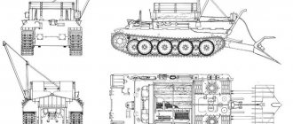
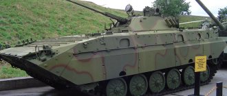
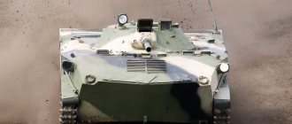
Universal bulldozer equipment, controlled by a driver from his workplace or an operator from the tower, is a bulldozer blade with a ski for adjusting the depth of the blade, which can be installed using a hydraulic system (without the crew leaving the vehicle) in a two-blade (as shown in the picture at the beginning of the article ) position, bulldozer position (as shown in the picture on the right), grader position (one wing is turned back as in a two-blade position, the other forward), and the bulldozer can tilt in the transverse direction. In the transport position, the dozer equipment can be tilted backwards (as shown in the photo on the left). This allows bulldozer equipment to perform the following work: 1. In a two-blade position - laying column tracks (by removing snow, bushes, debris, soil, non-explosive barriers, etc. on both sides of the route) for the movement of wheeled and tracked vehicles.2 . In the bulldozer position - digging pits, equipping descents, cutting off slopes, constructing passages through anti-tank ditches, counter-scarps.3. In the grader position - laying column tracks (by removing snow, bushes, debris, soil, non-explosive obstacles, etc. to one side from the route) for the movement of wheeled and tracked vehicles, creating a transverse profile of dirt roads, cutting out ditches, cutting off slopes .The telescopic boom working body, controlled by an operator from the tower, allows using a manipulator to grab and move various objects (debris, poles, tree trunks, various other objects) weighing up to 2 tons. Moreover, all this is done without the crew leaving the vehicle. With the help of the scraper included with the machine, which is installed on the manipulator, fine bulldozer work or excavation work is possible.
IMR-2 Combat weight, t 44.5 Length with equipment, mm. 9550 Width, mm 3735 Tower roof height, mm 3680
Ground clearance, mm. 475 Wed. beat ground pressure, kg/cm #178; 0.88 Obstacles to be overcome: – ascent, deg 30 – ford, m 1.2
Engine's type . diesel V-84-1 Max, power, hp. 840 Specific power, hp/t. 18.9 Maximum speed, km/h. 59 Power reserve, km 500
Reservation: combined projectile protection Crew 2 Radio station R-173
Additional information: Created on the basis of the main T-72 tank. On its basis, the IMR-2M1 and IMR-2M2 variants were developed in 1987 and 1990. Hydraulic system capacity – 500 l. Pumping unit capacity 456 l/min. The speed when working with bulldozer equipment is 8-12 km/h, the speed of making a passage in forest and stone rubble is 0.3-0.35 km/h. Maximum traction force 275 tf. The boom's load capacity is 2 tons, reach is 8835 -8435 mm. It is intended for laying travel routes over rough terrain and in various rubble. The vehicle can be used in places where weapons of mass destruction are used. The IMR-2 engineering clearing machine is equipped with a bulldozer blade installed in front of the machine body and capable of operating in a dual-blade, bulldozer or grader position, similar to the machine of the first modification. A ski can be installed in front of the blade, allowing you to adjust the degree of its penetration into the ground. The productivity of the IMR-2 machine when constructing passages is 300-450 m3/hour, when laying roads - 6-10 km/hour, when using bulldozer equipment - 230-300 m3/hour. The IMR-2 machine also has a telescopic boom with a manipulator-gripper for removing heavy foreign objects from the path. The boom is installed in a rotating tower, the maximum boom reach is 8.8 m, the load capacity is 2 tons, the maximum hook lifting height is 11 m. The boom has a universal attachment system for working parts: ripper, grab, grab and excavator equipment. The capacity of the excavator bucket is 0.5 m3. The productivity of the machine in excavator mode is 25 m3/hour of soil. A rutted knife mine trawl is installed in front of the engineering clearing vehicle, and in subsequent versions - with an electromagnetic attachment, for independently making passages in minefields equipped with anti-tank pin, bottom and magnetic mines. The IMR-2 engineering clearance vehicle is armed with a 7.62-mm PKT machine gun and an extended mine clearance charge. In the transport position, the IMR-2 engineering clearing vehicle throws a bulldozer blade onto the roof, lifts the mine trawl and moves the boom into itself, laying it back. The machine is capable of working in difficult to pass places.
| Weight (with spare parts kit), t | 1 |
| Trawling depth, mm | 100 |
| Installation time, min. | 15-20 |
| Dismantling time, min. | 5-10 |
| Trawling speed, km/h | 6-15 |
KMT-6 Mine trawl is an individual attachment to tanks for making passages in minefields. It is not intended for making passages in minefields for other vehicles. Structurally, the KMT-6 mine trawl consists of two knife sections of three knives each with inclined blades, two lifting mechanisms, electrical equipment, a winch, a coupling device in the form of two brackets installed on the booms of the lower frontal sheet of the tank, two electromagnetic EMT attachments and a folding rod for neutralization of anti-bottom pin mines. When the KMT-6 rutted knife mine trawl is operating, the knives go deep into the ground and, when the tank moves, they cut the soil. When encountering a mine, the latter slides up the knives and ends up on the dump, along which it is removed beyond the dimensions of the tank caterpillar. Electromagnetic attachments EMT imitate the magnetic field of a tank, provoking the explosion of magnetic mines at a distance of 1 - 4 meters from the vehicle. The lowering of the trawl into the working position is carried out using an electric drive, without requiring the driver to leave the vehicle. Two sections of the KMT-6 mine trawl are lifted into transport position using pneumatic cylinders via cables. MAIN TACTICAL AND TECHNICAL CHARACTERISTICS
The KMT-8 mine trawl is an individual attachment for T-55, T-62, T-64, T-72, T-80, T-90, T-90S tanks for making passages in minefields. The trawl is not intended for making passages in minefields for other vehicles. The KMT-8 track mine trawl consists of two knife sections of three knives each with inclined blades, two lifting mechanisms, electrical equipment, a winch, a coupling device in the form of two brackets installed on the booms of the lower frontal sheet of the tank, two electromagnetic EMT attachments and a folding rod for neutralization of anti-bottom pin mines. When the KMT-8 track mine trawl is operating, the knives go deeper and cut the soil. When encountering a mine, the latter slides upward along the blades and lands on the blade, thanks to which it is removed beyond the dimensions of the tank tracks. Electromagnetic attachments EMT imitate the magnetic field of a tank, provoking the explosion of magnetic mines at a distance of 1 - 4 meters from the vehicle. The folding rod ensures the elimination of anti-bottom pin mines. Lowering into the working position is carried out using an electric drive, and raising to the transport position occurs using pneumatic cylinders and cables. This operation does not require the driver to get out of the car. The rawl provides trawling of anti-track and anti-bottom mines with a reliability of 93% in various ground conditions and snow. The KMT-8 trawl consists of the following components and a set: – two knife sections (left and right) of the pneumatic system of the minesweeper winter (TUZ) device for trawling anti-bottom mines (UTPM) Individual spare parts Tactical and technical characteristics of the KMT-8 TTX rutted knife mine trawl Length 1.18 m, width 3.3 m Weight 1.1 t Weight of one knife section 0.4 t Trawling speed 6-14 km/h Width trawled strip in one section 0.60 m Width of the untrawled strip in the middle 2.16 m Obstacle to be overcome: elevation angle 20°, roll 20°, safe turning radius 65 m
The BAT-M track-laying machine is an engineering vehicle and is designed for laying advance routes, clearing rubble and roads, arranging trenches and shelters, etc. The BAT-M track-laying vehicle was developed on the basis of the AT-T artillery tractor (T-54 tank chassis). The driver's cabin is equipped with protection against weapons of mass destruction (WMD) with a filter and ventilation unit. Depending on the nature of the work ahead, the working body of the track-laying machine can be installed in a bulldozer, two-blade or single-blade position. In front of the BAT-M machine there is a bulldozer blade 5 m wide, and a dual-slope blade 4.5 m wide and a grader blade 4.0 m wide can also be installed. The blade can change its position in any direction using a hydraulic drive. This makes it possible to perform different jobs. There may be a special ski in front of the blade that regulates uniform removal of soil. The BAT-M tracklayer is equipped with a crane with a lifting capacity of 2 tons. The crane is controlled from a remote control panel. In the transport position, the blade is thrown onto the vehicle behind the driver's cabin. The BAT-M track-laying machine has enough fuel to complete the work within 12-15 hours. TECHNICAL CHARACTERISTICS — working width in two-blade position – 4.5 m; — working width in bulldozer position – 5 m; - productivity when laying column tracks in bushes, small forests and virgin lands - 4-8 km/h; — productivity when laying column tracks on virgin snow – 8-10 km/h; - productivity when moving soil when constructing ramps, slopes and ravines, filling anti-tank ditches - 100-200 m3/h; — productivity when making passages in stone rubble – 15-20 m/h; — crane lifting capacity – 2 tons; - boom radius - 5.4 m; — average speed on dirt roads is 20-22 km/h; — maximum speed – 35 km/h; — weight of the tracklayer – 27.5 tons; — crew – 2 people.
Application of IMR-
The IMR its first baptism of fire in Afghanistan. There they were used as part of traffic support units, their main functional purpose was clearing rubble, removing snow on passes and restoring roads.
Also, when moving combat groups, it was mandatory to create a combat guard, which also included IMR. In Afghan conditions, many functional IMR devices were not used, since there was no reason for their use. For example, anti-mine trawls and mine clearing launchers were practically not used.
IMR-2 truly tested in difficult conditions in Chernobyl. After the man-made disaster at the fourth power unit of the Chernobyl nuclear power plant. It was the IMRs who were sent to clear away the rubble at the reactor. Apart from them, no other equipment could be used there, since the IMR-2 had anti-radiation protection.
Currently, IMR is also being used, not only in the engineering troops, but also in the detachments of the Ministry of Emergency Situations in case of man-made and natural disasters. When extinguishing large forest fires using IMR, firebreaks are created. In fact, this special equipment can also be successfully used when demolishing old buildings, clearing clearings under power lines in forest areas, etc. Using this machine, you can also clean water bodies and fill new roads. In general, the scope of WRI for the benefit of civil society is broad enough to warrant consideration of its targeted use.
Article sent by: Brazil
Articles on the topic
0 56
Fire extinguishing aerosol generator
Published: August 28, 2018
Firefighting machinery and equipment
Fire extinguishing aerosol generator
Published: August 28, 2018
In railway transport, river and sea vessels, in cars, and at energy facilities, a fire extinguishing aerosol generator (FAG) is used to fight fires.
- Firefighter combat clothing. Types of BOP. Laying out and donning firefighter combat clothing.
- Testing stairs. PTV tests. Hose testing.
- Fire monitor. Portable fire monitor. Stationary monitor
Weapons and military equipment / Samples
Company participant: Uralvagonzavod, Research and Production Corporation, JSC
Designed for engineering support for the advancement of military columns and track equipment. The equipment allows the IMR-3M to independently overcome anti-tank minefields and make passages through them.
Developed by NPK "Uralvagonzavod" for the development of the machine
IMR-3
, adopted for service in 1999. The vehicle is tracked, like
IMR-3
made on a tank chassis
T-90
; previous models of equipment for the same purpose were made on tank chassis
T-72
(
IMR-2
/2M, 1980/1987) and
T-55
(IMR, 1969).
The vehicle weight is 50.8 tons, the maximum speed is 60 km/h on the highway, and the range on the highway is 500 km. Engine - four-stroke multi-fuel diesel
B-84
MS 840 hp
IMR-3
M is equipped with a universal bulldozer blade and a telescopic boom with a URO (“universal working body” - manipulator) on an electro-hydraulic remote control (maximum reach 8 meters, load capacity 2 tons). One of the working tools is a bucket with a capacity of 0.35 cubic meters.
Possible to equip with a knife track mine trawl
KMT-R3
with an electromagnetic attachment.
12 are mounted as weapons,
7 mm
NSVT machine gun. There is also thermal smoke equipment for setting up smoke curtains.
Completely sealed, capable of working even in areas contaminated with radioactive substances. Fords up to 1.2 meters deep can be crossed immediately without preparation, and the underwater driving system allows, with preliminary preparation, to pass water obstacles up to 5 meters deep along the bottom.
In forest and rocky rubble
IMR-3
M makes passages at an average speed of 300-400 meters per hour, in minefields - 5-12 km/h. In a snowdrift 120 cm high, he makes a path at a speed of 15 km/h. During excavation work (digging pits, filling ditches), the “digging” capacity is up to 250 cubic meters of soil per hour, and the “burrowing” capacity is up to 360 cubic meters per hour.
Specifications
| Weight with KMT-R3 trawl, t | 49,5 |
| Crew, people | 2 |
| Maximum speed, km/h | 60 |
| Cruising range on the highway, km | 500 |
| Engine | four-stroke, multi-fuel diesel V-84MS, 840 hp. |
| Depth of ford without preparation, m | 1,2 |
| length | 9320 |
| width | 3500 |
| height | 3430 |
| clearance | 426 |
| Load capacity, t, no more | 2 |
| Grab bucket capacity, m3 | 0,35 |
| Backfilling of ditches, trenches, m3/h | 350..360 |
| Construction of descents in steep banks and ravines up to 6 m high, m3/h | 350..400 |
| Clearing roads of snow and laying tracks through virgin snow with a snow depth of 1.2 m, km/h | up to 15 |
| Digging pits, m3/h | 200..250 |
| Soil loading, m3/h | 15..20 |
Design[edit]
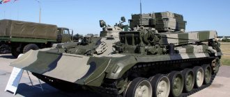
IMR-2 was created on the basis of the T-72 tank. The turret of the T-72 tank was replaced with a new rotating multi-purpose telescopic crane. IMR-2 has a bulldozer blade mounted on the front of the body, having a V-shaped and straight shape, with a productivity of 200 - 250 m 3 / h. When not required, the blade folds up. Rock barriers can be cleared at a speed of 280 to 350 meters per hour, while trenches and tree barriers can be filled at a speed of 350 to 400 m 3 / h. The NSVT 12.7 mm machine gun is mounted on the commander's and crew operator's cabin for machine self-defense.
Engineering clearing vehicle IMR-(object 616A).
An army vehicle designed for laying roads over rough terrain, in forests and city rubble, for digging and filling pits. Entered service in 1969. Years of production from 1969-1991. With bulldozer equipment, boom crane with lifting capacity of 2 tons with gripper-manipulator, scraper-ripper. Weight – 37.5 tons. Bulldozer equipment has three operating modes: double-blade, grader and bulldozer. Changing operating modes is done remotely using hydraulic drives. To adjust the degree of immersion of the knife, there is a controlled ski in front. In the grader position, the working width reaches 3.4 meters, when working in bulldozer mode - 4.15 m, and in double-blade mode - 3.56 m. The speed of making passages in a continuous forest rubble is 200-300 meters per hour, urban rubble is raked with speed of 160-200 meters per hour. The speed of making a column track on rough terrain is 5-8 km per hour. Telescopic boom 8.8 meters long and with a lifting capacity of 2 tons. To use the boom as a bucket, the IMR equipment set includes a special scraper-bucket with a volume of 0.4 m³ and a capacity of 40 m³ per hour. The chassis of the T-55 medium tank is used as the base. The machine body is sealed and has anti-nuclear protection. The total radiation dose received by the crew was reduced by up to 10 times. The bottom of the hull is reinforced with steel sheets, the turret sheet is changed. On the top sheet of the hull there is a turret for the driver. The IMR crew consists of two people: the driver and the commander-operator. For communication, the vehicle is equipped with a radio station R-113 or R-123. The IMR supply package includes the following weapons: 1 AKS-74U assault rifle, with 150 rounds of ammunition; 10 F-1 grenades; SPS signal pistol. Ammunition 30 rounds. Manufacturer: Novokramatorsk Machine-Building Plant (NKMZ). The real work for this machine was found in the terrible days of May 1986 at the fourth unit of the Chernobyl nuclear power plant. Only then was this car appreciated. The IMR turned out to be the only machine capable of operating near a destroyed nuclear reactor. She alone was able to clear the passages to the reactor, carry out the necessary measurements, and remove fragments of nuclear fuel rods scattered around the reactor and the remains of walls. She began to build a sarcophagus around the reactor, delivered and installed crane equipment. Almost all of the IMRs that were in service at that time ended up in Chernobyl and they all remained there forever. During operation, the machines picked up so much radiation that the armor itself became radioactive. Dozens, if not hundreds of IMRs, among hundreds of other vehicles, stand at an abandoned wartime airfield near Pripyat.
IMR ("object 637") is a Soviet engineering obstacle clearing vehicle.
The main purpose of the IMR-2: the creation of column tracks in difficult places for the advancement of troops, as well as the creation of passages in minefields. To perform these tasks, IMR-2 has: an electromagnetic EMT attachment and a mine clearance installation; bulldozer and crane equipment; track blade mine trawl with pin fuses. The IMR-2 machine was designed in Omsk at the Transport Engineering Design Bureau. The development was led by A.A. Morov. In 1980, the vehicle was put into service, and since 1982 its mass production has been organized. The car was mass-produced in Nizhny Tagil at Uralvagonzavod. The chassis of the T-72 main battle tank, which according to the GBTU classification had the designation “Object 637,” was taken as the base. The machine is equipped with bulldozer equipment, which has three operating modes: bulldozer, dual-blade and grader. Modes can be changed remotely without the crew leaving the vehicle. To adjust the depth of the bulldozer blade, there is a controlled ski in the front of the machine. The performance of a bulldozer allows you to fill ditches and craters, as well as move debris. The width of the bulldozer in the grader position is 3.4 m, in the bulldozer position - 4.15 m, and in the two-blade position - 3.56 m. In the stowed position, the bulldozer equipment is raised and located on the roof. The armored hull is completely sealed and provides protection for the crew from radiation with an attenuation coefficient of 10. In the stern there is a demining unit, and in the operator's turret there is an installation with a 7.62 mm PKT machine gun used as the main weapon. In addition to the machine gun with IMR-2, the following are supplied: Machine guns with 150 rounds of ammunition; 10 Granat F-1; Flare gun with 30 flares. The IMR-2 special equipment includes: underwater propulsion system; automatic fire extinguishing system; anti-nuclear protection system; filter and ventilation unit; X-ray radiometer DP-3B; smoke exhaust system; VPKhR chemical reconnaissance device. IMR-2 showed its high efficiency during the liquidation of the consequences of the accident at the Chernobyl nuclear power plant; it turned out that IMR-2 was the only machine that was capable of working in close proximity to a destroyed nuclear reactor. IMR-2 is also periodically used by Russian emergency services and the engineering troops of the RF Armed Forces .
This is interesting: Fire smoke exhausters DPM, DPG, DPE: characteristics
Links[edit]
- ^ a b "IMR-2 combat engineering vehicle". Military-today.com.
- "Engineering heavy armored vehicle for overcoming obstacles of the IMR-2 series". armyrecognition.com.
- https://www.armyrecognition.com/november_2018_global_defense_security_army_news_industry/last_batch_of_imr-3m_engineer_armored_vehicles_delivered_to_russian_mod.html
- https://www.armstrade.org/includes/periodics/news/2018/1116/100049656/detail.shtml
- https://eng.mil.ru/en/news_page/country/
| vteTanks converted into armored vehicles | ||
|
| |
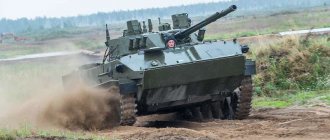
IMR-3M is a Russian engineering obstacle clearing vehicle.
In 1999, the IMR-3 engineering obstacle clearing vehicle entered the Russian Armed Forces. The chassis of the T-90 tank is used as the base. A modernized engineering vehicle based on the T-90 tank. Designed for engineering support for the advancement of military columns and track equipment. The equipment allows the IMR-3M to independently overcome anti-tank minefields and make passages through them. Developed by NPK Uralvagonzavod. The tracked vehicle, like the IMR-3, is made on the chassis of the T-90 tank; previous models of equipment for the same purpose were made on the chassis of the T-72 (IMR-2/2M, 1980/1987) and T-55 (IMR, 1969) tanks. The vehicle weight is 50.8 tons, the maximum speed is 60 km/h on the highway, and the range on the highway is 500 km. The engine is a four-stroke multi-fuel diesel V-84MS with a power of 840 hp. With. IMR-3M is equipped with a universal bulldozer blade and a telescopic boom with a URO (“universal working body” - manipulator) on an electro-hydraulic remote control (maximum reach 8 meters, load capacity 2 tons). One of the working tools is a bucket with a capacity of 0.35 cubic meters. It is possible to equip it with a knife track mine trawl KMT-R3 with an electromagnetic attachment. The weapon is a 12.7 mm NSVT machine gun. There is also thermal smoke equipment for setting up smoke curtains. Completely sealed, capable of working even in areas contaminated with radioactive substances. Fords up to 1.2 meters deep can be crossed immediately without preparation, and the underwater driving system allows, with preliminary preparation, to pass water obstacles up to 5 meters deep along the bottom. In forest and rocky rubble, the IMR-3M makes passages at an average speed of 300-400 meters per hour, in minefields - 5-12 km/h. In a snowdrift 120 cm high, he makes a path at a speed of 15 km/h. During excavation work (digging pits, filling ditches), the “digging” capacity is up to 250 cubic meters of soil per hour, and the “burrowing” capacity is up to 360 cubic meters per hour. Today, IMR-3M is one of the most promising and advanced engineering barrier clearing vehicles. Possessing a sealed casing, it is capable of performing tasks in conditions of high concentrations of aggressive gases, toxic substances, vapors, dust, smoke in the atmosphere, as well as in areas exposed to radioactive contamination (the crew works without personal protective equipment), and in conditions of direct fire resistance from the enemy . The vehicle is equipped with radiation, chemical reconnaissance and dosimetric monitoring devices. The installed underwater driving equipment allows the vehicle to cross water obstacles up to 5 m deep along the bottom. The tasks solved by the IMR allow it to be classified as dual-use equipment. It shows equally high operating efficiency both as an IMR and as a rescue vehicle. The IMR-3M is equipped with the latest communications equipment.
IMR-2
Part one. A little history
It so happened that the history of engineering technology, in contrast to the history of aviation, tanks and even fortification, is always given very little attention. It all comes down to technical specifications and year of manufacture. This is understandable - information on the history (EXACTLY HISTORY!) of engineering technology is very insignificant. In this article, the author tried, as far as possible, to reveal some points in the history of the development of the IMR-2 engineering barrier vehicle. This issue still remains relevant, especially on the next anniversary of the accident at the Chernobyl nuclear power plant, where IMRs demonstrated all their capabilities.
During combat operations, there is a need to ensure the movement of troops along routes (military roads) or their equipment and support. In 1933, the concept of a column route was introduced - a direction chosen on the ground outside of roads, prepared for short-term movement of troops. The main work to prepare the column route was: marking the route, reducing the angles of descent and ascent, strengthening wetlands with wooden shields, clearing the path from rubble, snow, mines, etc. New machines developed on the basis of the ChTZ tractor are being adopted: a bush cutting machine, a tractor shovel, mechanized rollers, and a snow blower. At the end of the 1930s. The troops receive bulldozers, ditch diggers, and the like. After the war in the 1950-60s. More advanced machines BAT, BAT-M, and more advanced attachments were developed. But the greatest development of machines for preparing and maintaining column tracks, ensuring the rapid advancement of troops, and clearing rubble, including in urban areas, was achieved during the period of the emergence of nuclear missile weapons (the second half of the 1960s). An increase in the volume of tasks, changes in their content, terms and conditions of implementation led to the creation of an engineering machine for clearing IMR.
Engineering clearing vehicles belong to a group of vehicles designed to make passages, clear debris and destruction during engineering support for military operations of troops, including in radioactively contaminated areas. To perform these tasks, the machines are equipped with bulldozer, crane and additional (bucket, scraper, drill) equipment.
IMR-2M makes a passage in a forest rubble
The bulldozer equipment in such machines is universal. It can be installed in one of three positions: - two-dump, which is the main one and is intended for making passages in rubble and destruction, laying column tracks, removing the upper radioactively contaminated layer of soil; — bulldozer, which is used when constructing ramps, filling excavations, moving soil and self-digging; — grader, used when constructing column tracks on slopes and other types of work that require moving soil (snow) in one direction.
Boom equipment in most cases is equipped with a gripper-manipulator, which allows you to perform a large range of work on constructing passages in forest and stone rubble.
As additional equipment, the vehicle can be equipped with a mine clearance unit and a mine trawl.
This group of vehicles also includes sapper tanks and some engineering vehicles that can be used for engineering work under enemy fire and in conditions of massive destruction (American M728 sapper tank, German Pionierpanzer-1, etc.).
IMR first
The first Soviet IMR was developed in Omsk on the basis of the T-55 tank. It entered service in 1969. The main equipment of the vehicle included a universal bulldozer and crane equipment with a manipulator. It should be noted that a vehicle of this class appeared in the West (in the USA) four years earlier: in 1965, the M728 “engineering (sapper) tank” entered service. The American was superior to the Soviet machine in terms of lifting capacity of crane equipment (8 tons versus 2 tons on the IMR), but the Soviet machine was lighter, more maneuverable and more versatile due to the manipulator with a gripper.
With the adoption of a new generation of tanks (T-64, T-72, T-80) and changes in the organizational structure of tank and motorized rifle units (the “Division - 86” program), the need arose to create a new barrage vehicle on a more modern base. The IMR-2, based on the T-72A tank, became such a vehicle.
Work on the IMR-2 began in 1975. The machine (general idea and design) was developed in Omsk under the leadership of A. Morov, and the working equipment and development of design, engineering and technological documentation in the Chelyabinsk SKB-200 and the Novokramatorsk Machine-Building Plant (chassis modification , hydraulics, lead developer of experimental machines).
The main working equipment - a telescopic boom and a bulldozer blade - were worked out on the previous machine, and their modernization and adaptation to the IMR-2 did not cause any difficulties. New equipment on the vehicle was a mine trawl and a mine clearance unit. Let's look at them in more detail.
The new equipment was developed by a special design bureau of the Chelyabinsk Tractor Plant - SKB 200, under the leadership of V. A. Samsonov in cooperation with the Novokramatorsk Machine-Building Plant. B. Shamanov and V. Samsonov were in charge of the demining launcher, and V. Gorbunov was in charge of the anti-mine trawl. The work was carried out under the general guidance of the head of the advanced development bureau, V. Mikhailov.
Designer of SKB-200 V. Mikhailov
If everything went more acceptable with the mine trawl, then the location of the launcher on the IMR body, Samsonov’s proposal, did not suit the main developer of the vehicle. Four cassettes with demining charges (total weight 1200 kg) were located at the rear of the vehicle and were tightly bolted to the hull. At the same time, they hung over the transmission hatches, which had to be opened during daily maintenance. In addition, although the cartridges with charges were moved as far back as possible, it was difficult to turn the IMR manipulator boom forward from the stowed position. Even in the raised position, the manipulator boom touched the top of the cassettes. All this did not suit the lead developer, and he raised the question of excluding the PU from the IMR. But the military insisted on their own. The head of the advanced development bureau, V. Mikhailov, proposed making the mine clearance launcher trailed, since several years ago such an option on the KB-200 wheelbase was already being developed. It was much easier and cheaper. But there was a task approved from above, and it had to be carried out. (About 10 years later, a similar MICLIC demining installation appeared in the USA. The charge was a chain of 140 C4 explosive blocks strung on a cable. The minefield was delivered using a powder rocket. The charge was stacked and transported in a single-axle trailer container.)
PU guide installed in the stern
V. Mikhailov’s next proposal was as follows: install the cassettes on the frame, and move the frame as far back as possible so that the cassettes do not interfere with the manipulator’s boom. Strengthen the part of the frame hanging from the stern with spacers. The proposal was accepted. In addition, it was proposed to make the charge cassettes out of wood and discardable after shooting the demining charge, which made it possible to reduce the weight of the vehicle by 600 kg (at the IMR there was an excess of 2 tons, so they looked for any way to reduce the weight of the vehicle).
IMR-2. The demining charge launcher at the rear of the hull and large boxes for demining charges are clearly visible
Wooden cassettes not only reduced weight, but also did not collapse when dropped from the machine (metal cassettes were often deformed). Also, the presence of wooden cassettes with demining charges made it possible to simply change them instead of (as was previously provided) reloading them into metal cassettes. Resetting the cassettes also satisfied the requirements of the lead developer, since the working conditions of the boom improved. An original method was invented to reset demining charge cassettes. The cassettes were placed on frames, which moved on special half-blocks outward to provide access to the transmission hatches. To reset, they decided to use the tension force of the brake rope, which held the demining charge in flight. The rope was attached to half-blocks under the cassettes. When the rope was pulled, the half-blocks rotated, releasing the cassettes and releasing them.
There were also minor problems with the installation of the mine trawl. Its developers were not satisfied with the small amount of space between the bulldozer raised into the stowed position and the vehicle body. This was literally a slot for a knife trawl, which, in the stowed position, also had to lie on the upper part of the IMR’s bow. At first, there was a proposal to abandon the knife rut trawl, and place its knives across the entire width of the IMR bulldozer (this was done on the American T5E3 trawl) and make them removable. This could result in a minesweeper with a passage width of about 4 m. But the officers of the Scientific and Technical Committee of the Engineering Troops didn’t even want to listen (again, ten years later this idea was embodied in the American COV clearance vehicle, in Russia they have now returned to this idea in the engineering road vehicle - RF patent No. 2202095). After a long search for a solution, we came to the conclusion - to take the old knife sections from the KMT-4M trawl, since they were smaller in size compared to the new KMT-6 sections. The trawl was raised to the stowed position by hydraulic cylinders. To mine mines with a pin fuse (TMK-2 type), the knife sections were equipped with two horizontal spring-loaded rods.
Mine trawl KMT-4 in stowed position
Trawl KMT-4 in working position. Metal rods located horizontally and intended for trawling anti-bottom mines with a pin fuse are clearly visible
Gradually, all the issues were resolved and the developers began producing prototypes of the IMR. A mechanic, a welder and a designer went from Chelyabinsk to Kramatorsk to install an anti-mine trawl and mine clearing launcher on the clearance vehicle. Later, the head of military acceptance, Colonel N. Omelyanenko, and designer V. Mikhailov went there to accept the IMR.
And in April 1977, prototypes of the IMR were sent for factory (preliminary) tests near Tyumen, on Lake Andreevskoye. V. Mikhailov wrote that he had bad memories from the tests: the officers who supervised the tests of the launcher and trawl made many deviations from the test program, and operating and safety instructions were often violated. Also, after launching the demining charge, it was necessary to measure its deflection: plus or minus 10% in range and 5% to the sides. All this had to be measured at a lateral wind speed of no more than 5 m/sec. But this was neglected. So, after the next launch (the lateral wind speed reached 8 m/sec), the charge left at an angle of 450 from the direction of the launch. The angle was recorded, but the wind speed was not. The only consolation for V. Mikhailov was that when the brake rope was pulled, even at an angle of 450, the empty charge cassettes were thrown from the side to the ground. During the next launch, another emergency occurred: the force of the flame from the jet engine of the demining charge was blown into the cracks above the vehicle’s transmission by the wind, and the fire sensors were activated. The space in the car was filled with inert gas. The operator and driver (young soldiers) were terribly scared. When leaving the car, the driver hit his head on the hatch and received a slight concussion (he was wearing a headset). After this, it was written in the operating instructions that the charge should only be started with the shutters of the transmission compartment closed. After testing the launchers, we began testing the mine trawl. Since there was still snow, the trawling of inert mines was carried out using a winter trawling device (TUZ): special grids made of plates were put on the handle knives of the trawl. Of the 180 mines laid in the snow, only two were missed, i.e. trawling quality was 99%. The quality of trawling mines installed in the ground was 100%. In general, the tests of the mine clearance and trawl launcher were successful.
The same tests showed that another 150 kg of weight can be saved on the car - this is the protection of the detonation transmission device (DTD). Shooting the demining charge and the UPD from small arms showed that this did not cause them to explode. Therefore, the position of the UPD was slightly changed (it was placed with a charge in the cassette) and another test was carried out in January 1978. They passed near Kharkov in the presence of the chief of the engineering troops of the 6th Army, Colonel Alekseenko. In honor of Alekseenko, they fired a live demining charge (800 kg) and then blew it up. The tests were successful. Next were the state tests, which took place in the summer near Kiev. They ended successfully, although they were overshadowed by tragedy - SKB-200 designer V. Gorbunov was seriously injured. The cause of the tragedy is trivial - a violation of safety regulations. During one of the launches, the guide with the charge did not rise to the required angle (by 100 instead of 600). Something happened to the power grid. According to the instructions, it was necessary to turn off the electrical equipment of the machine. This was not done. The work manager called the designers from Kramatorsk (the main developer), who ordered the electrician to see what had happened. V. Gorbunov immediately approached. Instead of driving the electrician away and performing all the operations according to the instructions, he stood behind the control panel. At this time, the electrician closed the starting circuit of the jet engine (which, again, contrary to the instructions, was located on the guide). The force of the flame hit the electrician in the shoulder and Gorbunov right in the face. V. Gorbunov was treated for a long time, but it was not possible to completely restore his vision and hearing.
After all the tests, documentation for serial production was prepared and secured. In 1980, by decree of the Central Committee of the CPSU and the Council of Ministers of the USSR dated 04/28/80 No. 348-102 and by order of the Minister of Defense dated 06/03/80 No. 0089, the engineering clearing vehicle was adopted by the Soviet Army under the designation “IMR-2”.
In May 1981, a group of IMR-2 creators from Kramatorsk and Chelyabinsk were awarded orders and medals. Thus, V. Gorbunov, who was injured during the tests, was awarded the medal “For Valiant Labor.”
IMR-2 (Novograd-Volynsky)
At first, the IMR-2 was supposed to be produced in Omsk at a local transport engineering plant, but since 1976 it was reoriented to the production of T-80 tanks. Therefore, by a resolution of the Central Committee of the CPSU and the Council of Ministers of the USSR dated July 27, 1977, this responsibility was assigned to Uralvagonzavod (Nizhny Tagil), where the construction of a special building was planned. But its construction was delayed, and the first 10 IMR-2 chassis were assembled in tank workshops. Only in 1985 did mass production of the IMR-2 chassis begin, which was then completed at the Novokramatorsk Mechanical Plant.
IMR-2 is intended for equipping passages, clearing debris and destruction during engineering support of military operations of troops, including in radioactively contaminated areas. In addition, it can be used for towing damaged equipment from troop routes, for carrying out rescue operations in areas of mass destruction, and the like.
The first IMR-2s began to enter service at the beginning of 1986. Lieutenant Colonel Evgeny Starostin recalls, who in 1985-1991. served in the 306th separate engineer battalion of the 24th MD (Yavorov, Ukraine) as a platoon commander and later a company commander:
— In February-March 1986, we received new equipment. These were IMR-2 engineering clearing vehicles. Re-equipment with new vehicles took place in accordance with the General Staff directive on the reorganization of the Armed Forces, and more specifically within the framework of the “Division-86” program. At this time, a new offensive doctrine appears, the staff of the units changes, everyone receives new equipment that could ensure offensive operations, in this case, our mechanized division. In engineering subsections, such a machine was the IMR-2. When we received new cars, there were certain difficulties. Firstly, they were driven off the railway platforms by tankers, because mechanics for IMR-2 were trained in the Baltic states, and at the time the new equipment was received in the division there were simply none. The tankers generally helped a lot. But basically I had to do everything myself: read the technical “Manuals”, press the buttons myself, press the levers. I learned on older tanks, and the T-72 tank as a base vehicle was new to me. In general, IMR-2 was similar to the previous IMR, but the internal equipment was smaller in size. A novelty was the appearance of a knife trawl and a mine clearing installation. Regarding control, in IMR-2 it was simpler and easier, unlike IMR, due to the fact that there was a hydraulic transmission rather than a mechanical one. The ESD system is also new. What is its essence? When the GO-27 radiation and chemical reconnaissance device detects a threat, the system stops, turns off the engine, all the blinds are closed and the car is sealed, the power supply is turned off, only the radio and emergency lights work. After 4.5 sec. The filter and ventilation unit is turned on. Then (after about 15-20 seconds) you can start the engine. When I first tried the PAZ on myself, I was shocked - the engine stalled, the car stopped, everything was knocking, closing, the lights went out. Feels like sprat in a jar. It’s funny now, but then... The working part - the manipulator - and the peculiarity of working with it turned out to be very successful. It was lightweight and very versatile. Thus, my old-time soldiers managed to close an open matchbox using a manipulator. As for the most basic vehicle - the T-72 tank, I will say that the vehicle is protected, comfortable, reliable, and easy to operate.
It should be recalled that to the main equipment (bulldozer, crane, mine trawl) a demining unit has been added, which is located at the rear of the machine and includes right and left guides with demining charges. Its presence was determined by the fact that IMR-2 would make passages in enemy minefields and mine-explosive barriers to ensure the advancement of troops.
IMR-2. Bulldozer oval and boom with gripper-manipulator in stowed position, and mine clearing charge launcher raised to firing position
Evgeny Starostin:
— Regarding the UR-83 demining installation. It is not known why she was on this car at all. There were many problems with her. Suffice it to say that the charges for the installation were located in wooden boxes on both sides of the vehicle. And this is 1380 kg of explosives. And this is on a vehicle that should operate in the first echelon, along with tanks. An RPG grenade hit, or a burst of bullets - and the car seemed to not exist (the launch distance of the charges is only 500 m). Preparation for the launch of demining charges was carried out manually, with the crew exiting the vehicle! And this was during the battle... Another problem was the launch of the charges, which were located near the engine compartment. And if the driver forgot to close the blinds of the agile compartment, then the starting engines of the mine clearance charges could damage the engine and cause a fire in the car. During the liquidation of the accident at the Chernobyl station, it was generally useless, it only caused a lot of problems for the special officers (the installation was secret).
Description of the design and main performance characteristics
Structurally, IMR-2 consists of a base machine and working equipment.
— The base vehicle (item 637) is an armored tracked vehicle made on the basis of components and assemblies of the T-72A tank, and is intended for mounting various equipment on it. To achieve this, some changes were made to the body of the “Product 637”: the bottom was reinforced, the design of the turret plate was changed, observation devices were replaced with sight glasses, fastening elements for working equipment were welded to the bow of the body, etc. The body of the vehicle is divided into two compartments: control and transmission. The control compartment is located in the bow (driver's seat) and middle parts of the hull (operator's seat). The transmission compartment occupies the rear part of the hull; it houses the vehicle’s engine, located transversely and shifted to the left side.
For driving along a given course in conditions of limited visibility and lack of landmarks, the base vehicle has a gyro-compass. The driver's surveillance devices include day and night surveillance devices, which ensures driving and operation of the IMR-2 at any time of the day. The vehicle is also equipped with a protection system against weapons of mass destruction, a smoke emission system and fire-fighting equipment. For defense, the vehicle is armed with a 7.62 mm machine gun, which is mounted above the operator's turret.
IMR-2 base chassis
— The working equipment of the machine consists of a universal bulldozer, a telescopic boom with a gripper, a rutted mine trawl, and a demining unit.
The universal bulldozer is designed for developing and moving soil, clearing snow and bushes, felling trees, uprooting stumps, making passages in forest debris and destruction.
Universal bulldozer IMR. Front view
It consists of a frame, lifting, lowering and tilting mechanisms, a small central blade and two lateral movable wings. The central blade is a welded structure that is attached to the frame and can be rotated to the right and left by 100. The blade wings (right and left) are similar in design, their front sheets have a curved surface. Knives are bolted to the bottom of the front sheet. Thanks to the mobility of the side wings, the bulldozer can occupy one of three positions: bulldozer, double-blade (path-laying) and grader. The universal bulldozer is controlled by the driver without leaving the vehicle.
The main working body - a telescopic boom - is hinged to the tower bracket located on the turntable. The boom has an original manipulator that copies the actions of a human hand and has six independent positions. The boom and manipulator are controlled by the machine operator from a remote control in the tower using an electro-hydraulic system. During operation, the following operations can be performed: turning the boom, raising and lowering the boom, extending and retracting the boom, raising and lowering the gripper, rotating the gripper, opening and closing the gripper. The design of the boom equipment allows you to combine individual operations, but no more than two. For example, turning the boom and opening (closing) the gripper, etc.
Gripper in working position
The KMT-4 track mine trawl is an integral part of the IMR-2 and is designed for the vehicle to independently overcome anti-tank minefields of all types of anti-tank mines, incl. anti-bottom with a pin fuse. The trawl consists of three main parts: the right and left knife sections (of a similar design) and the transfer mechanism. The knife section consists of a working element (three handle knives, a box-shaped blade, a folding wing), a balancer, a balancing device, a pin device for trawling anti-bottom mines, a ski that follows the terrain, and a winter trawling device. In the working position, the trawl blades are buried in the ground. If a mine comes across their path, it is removed from the ground with knives, falls onto the dump and is moved to the side behind the track of the tank tracks.
A mine clearing installation (MD) is an additional equipment to a mine trawl and is designed to make passages in enemy minefields and mine-explosive obstacles in order to ensure the advancement of troops. It is located in the rear part of the vehicle body and consists of two (right and left) guides for launching mine clearance charges. A jet engine is placed on the guide, which, when launched, pulls a mine clearance charge and sends it to the minefield. The mine clearance charges themselves are located in wooden cassettes (two per side) in the rear of the hull on the fenders. The crew prepares the charges for launch manually after exiting the vehicle.
Rear view of the mine clearing launcher
Main performance characteristics of vehicles
Base vehicle: tracked base of the T-72A tank (item 637). Weight with removable elements (knife trawl KMT, UR), t: 45.7. Crew, people: 2. Productivity: — when preparing column tracks on moderately rough terrain — 6-10 km/h; — when equipping passages in forest rubble — 340-450 m/h; — when equipping passages in stone rubble — 300-350 m/year; — when developing soil with bulldozer equipment (filling ditches, craters, etc.) — 230-300 m3/year. Obstacles to be overcome, degrees: — maximum climbing angle — 30; — maximum roll angle — 25. Width of the bulldozer blade, m: — in a two-blade position — 3.56; — in bulldozer position — 4.15; — in the grader position — 3.4. Boom lifting capacity, t: 2. Speed, km/h: — on the highway — 50; — on dirt roads — 35-45. Launcher: - number of guides, pcs.: 2. - max. lifting angle of the guides, degrees: 60. — supply range of the mine clearance charge, m: 250—500. Power reserve, km: 500.
Perform basic engineering tasks
Passages in forest debris are made by pushing apart the bulk of the blockage with a bulldozer blade, as well as by pulling out and removing individual trees with a boom and a manipulator that impede the work of the bulldozer (usually sticking out above the level of the blade or posing a threat of damage to elements and components of the machine). In this case, the bulldozer blade is installed in a two-blade position, and the boom with the manipulator is deployed and installed with a grip in front of the blade.
Passages in stone dams, depending on their height and length, are made either by clearing to a solid base with a dam height of up to 50 cm, or, with a higher height, by constructing a passage on top, for which an entrance and exit from the dam is arranged. If the height of the dam is high, its crest is collapsed using a manipulator, large fragments are removed to the side or placed on a ramp.
In rubble in populated areas, IMR makes passages in the same way as in stone rubble. But at the same time, on the sides of the rubble it is necessary to bring down dangerous elements of buildings (walls), pillars, masts, etc.
IMR-2 arranges exits to the crossings by cutting off the coastal steepness (cliff) or cutting off the slope. When cutting a slope, the travel lane is arranged in the form of a half-cut - half-embankment by successive cutting of the slope. In this case, the blade is placed in the grader position, and the cutting itself is performed with the blade wing turned forward.
The machine makes felling of individual trees with a diameter of 20-40 cm by cutting them at the root with a blade. Trees with a diameter of more than 40 cm are felled with a manipulator with simultaneous or preliminary pruning of the root system. Uprooting stumps with a diameter of up to 40 cm is carried out by cutting the root system by deepening the blade by 15-20 cm 2 m before the stump.
The machine digs a pit with a blade installed in a bulldozer position, with a sequential reciprocating movement. The earth from the pit is periodically moved onto the parapets.
In radioactive and chemically contaminated areas, IMR performs all types of the above work, but with the machine completely sealed.