In accordance with the resolution of the USSR Defense Committee, at the end of 1938, the Kirov plant in Leningrad began designing a new heavy tank with projectile-proof armor, called SMK (“Sergei Mironovich Kirov”). The development of another heavy tank, called the T-100, was carried out by the Leningrad Experimental Engineering Plant named after Kirov (No. 185).
The leading designer of the SMK tank was A. S. Ermolaev. The initial project envisaged the creation of a three-turreted vehicle, with its mass reaching 55 tons. During the work process, one turret was abandoned, and the saved weight was used to thicken the armor. In parallel with the SMK, from February 1939, the Leningrad Kirov Plant began designing a single-turret breakthrough tank, which received the name KV in honor of the People's Commissar of Defense K.E. Voroshilov. Engineer N.L. was appointed the lead designer of the tank. Dukhova. The technical design of the machine was prepared within a month. In accordance with the project, a new V-2 diesel engine with a power of 500 hp, developed in Kharkov, was installed on the tank. In fact, the KB was a SMK roadwheel reduced in length by two with one turret and a diesel engine. The name KV-1 began to be used in 1941; before that it was designated as a “tank with a small turret” (there was also a “tank with a large turret” - KV-2).
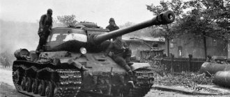
By September, the car was ready and entered testing, during which unstable engine operation and a future weak point were revealed - an unreliable gearbox. The problems were partially resolved, but the gearbox remained the same. There were major problems with the clutch and transmission, which affected the mobility of the tank. When changing gears, the tank stopped and could not quickly gain speed. The US Army tested the transmission (in 1942) at the Aberdeen Tank Proving Ground and concluded that it was obsolete and could not be adopted as it was very difficult for the driver to operate. Ineffective air filters negatively affected engine performance. All these factors combined worsened the control of the tank. The KV tank was removed from testing to be tested in a combat situation during the Soviet-Finnish war that began on November 30, 1939. The first copy was armed with two guns: 76- and 45-mm, mounted in the same turret. Before being sent to the front, for the convenience of the crew, the 45-mm gun was dismantled and replaced with a DT machine gun. The experienced KV was on the front line until January 1940. While participating in combat operations, the tank demonstrated invulnerability from anti-tank gun fire.
Tactical and technical characteristics of Soviet heavy tanks of the late 1930s.
Layout of the KV-1 tank
The KV-1 tank had a classic layout with a rear-mounted transmission.
Inside, the tank's hull was divided into four compartments: control, combat, engine and transmission. The control compartment was located in the bow of the tank. It contained the seats of the driver (in the center) and the gunner-radio operator (on the left). To the left of the radio operator's seat there was a radio station, and behind it were four batteries. In the middle of the frontal armor plate of the hull there was an inspection hatch for the driver, closed by an armored cover with an inspection slot with triplex. To the right of the driver, a mirror viewing device was installed in the roof of the hull. In front of the gunner-radio operator, in the front plate there was a ball mount for a course machine gun. An entrance hatch was made in the roof of the tank above the radio operator's seat, which was closed with a hinged armored cover. In addition, the control compartment housed tank controls, air cylinders with valves and instruments, fuel valves and a pump, and control devices.
The fighting compartment occupied the middle part of the vehicle. It contained seats for the gunner (to the left of the gun), the tank commander and the loader (to the right of the gun). A turret was mounted above the fighting compartment on a ball support; weapons were installed in it and part of the ammunition was stored. Fuel and oil tanks were located along the sides of the fighting compartment, and part of the ammunition rack and VCU were located on the bottom. To monitor the battlefield, mirror viewing devices were installed in the roof of the tower along the sides and in the rear. In addition, there were viewing slots with glass blocks in the sides of the tower. For landing the crew, an entrance hatch was provided in the roof of the tower, closed with an armored cover. On some vehicles, at the base of the hatch, there was a turret for installing a spare machine gun for firing at air targets.
The engine compartment followed the combat compartment and was separated from it by a collapsible partition. The engine, water and oil radiators and an air cleaner were installed in the compartment. The partition separating the engine compartment from the combat compartment had two hatches intended for access to the engine from the combat compartment of the tank. Portholes were mounted in the upper doors of the hatches to monitor the engine.
The transmission compartment was located in the rear of the tank and was separated from the engine compartment by a special partition in which the fan casing was attached. In addition, the partition had doors for access to the air purifier. This compartment housed the transmission units and electric starter.
KV-1 tank hull
The tank's hull was a rigid welded box made of rolled armor plates with a thickness of 30 to 75 mm. To ensure rigidity of the body, angles and pads were used.
The nose of the hull consisted of upper, middle and lower armor plates made of homogeneous armor with a thickness of 75.40 and 75 mm, respectively. Beginning in July 1941, the upper and lower frontal plates were strengthened by welding 25 mm thick applied armor plates to them. There were two cutouts in the upper frontal plate: one for the driver's inspection hatch, the second for the installation of a forward machine gun. On the middle frontal plate on the left there was a cutout for installing an antenna input, covered with a welded armor cup. Two towing eyes were welded on the lower frontal sheet.
The side of the hull was made of one vertical armor plate, which had six holes for the passage of the balancer axes, six brackets with platforms for attaching rubber stops that limited the upward movement of the balancers, as well as holes for attaching three brackets for the support rollers.
A guide wheel crank bracket was welded to the front of each side plate, and there was a hole at the rear to install the final drive. Beginning in July 1941, in the area of the fighting compartment, 25 mm thick applied armor plates were welded to the sides of the hull. Reservation scheme for the KV-1 tank
The rear of the hull consisted of upper (60 mm) and lower (75 mm) armor plates, between which there was a pocket for air outlet. Two towing eyes were welded to the lower stern plate. From the beginning of 1942, on some armored hulls the upper armor plate began to be made straight rather than bent.
The roof of the hull consisted of three parts - the roof over the fighting compartment, the roof over the engine compartment and the roof over the transmission compartment. The roof over the fighting compartment was made of 40 mm armor plate, in which there was a round cutout for installing the lower shoulder strap of the turret support. On the removable armored cover of the engine compartment, 30 mm thick, there was a hatch for access to the engine, two exhaust pipes, two openings for the entrance of cooling air and a hatch for filling water into the cooling system filler tank. There were two hatches in the roof of the transmission compartment, intended for access to the transmission mechanisms.
To protect the turret ring, armor strips up to 80 mm high and 40 mm thick were welded onto the hull roof.
The bottom was butt welded from two armor plates. In the front part of the hull it had a greater thickness of armor (40 mm) than in the rear (30 mm). In the front part of the bottom, behind the driver's seat, there was a spare (emergency) hatch. In the rear part of the bottom there were four holes for draining oil and water and one sub-engine hatch.
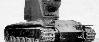
T-100
| T-100 | |
| TTX/Tank brand | 1939 |
| Combat weight, kg | 58000 |
| Crew, people | 8 |
| Size, mm | |
| Total length | 8495 |
| Width | 3400 |
| Height | 3430 |
| Clearance | 525 |
| Track width | 710 |
| Armament | |
| Guns, pcs. x cal. | 1x76.2 mm L-10 |
| 1x 45 mm 20K | |
| Shells, pcs. | 76.2 mm - 120 |
| 45 mm - 393 | |
| Machine guns, pcs. x cal. | 3×7.62-mm |
| Machine gun type | DT |
| Cartridges, pcs. | 4284 |
| Armor thickness, mm | |
| Vert. housing | 60-30-20 |
| Horizon housing | 20-30 |
| Tower | 60-30 |
| Engine | |
| Type | 4t/12ts/k/zh |
| Brand | GAM-34 |
| Power max., hp | 850 |
| At rpm | 1850 |
| Gearbox transmission | 5/1 |
| Speed max., km/h | 35.6 |
| Fuel type | Gasoline 1s |
| Capacity tank, l | 1160 |
| Cruising range, km | |
| - highway | 170 |
| - country road | 120 |
| Obstacles to be overcome | |
| Ud. pressure, kgf/cm2 | 0.68 |
| Rise, deg. | 42 |
| Descent, deg. | 42 |
| Roll, deg. | 25 |
| Ditch, mm | 4000 |
| Wall, mm | 1200 |
| Brod, mm | 1250 |
KV-1 tank turret
The tower is riveted-welded, faceted, in plan close to the shape of a rectangle, with a rear niche.
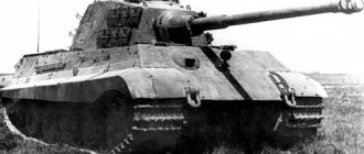
Some tanks, starting in November 1941, were equipped with cast turrets. The thickness of the armor plates of the welded turret was 75 mm, the cast one was 82 mm (for the so-called “weighted” turret it was 110 mm). The trough-shaped armor of the cannon and the coaxial machine gun was covered from the outside with an armor mask 90 mm thick. A cutout was made in the rear sheet for installing a ball bearing for the machine gun.
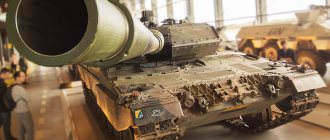
KV-1 tank with a cast turret manufactured by UZTM and additional hull armor. It was this machine that was tested at the Aberdeen Proving Ground in the USA in 1942
The sides of the turret had viewing slots with glass blocks, one on each side, and under them there were holes for firing from a revolver. The holes were closed with conical armor plugs, which were pushed out of the hole manually and pulled back in using a steel cable.
There was a round entrance hatch in the roof of the tower, which was closed with an armored cover. The design of the entrance hatches and the hatches above the transmission compartment was the same, with the exception of the turret entrance hatch, around the circumference of which a turret for an anti-aircraft machine gun was mounted. The lower support of the turret was riveted to the roof of the tower, and the upper one, on which the hatch cover and balancing device were mounted, rotated along the lower support on balls.
In the front part of the roof there were armored caps for the PT-6 sight and the PTK tank commander panorama, and between them there was an armored cap for the ventilation hatch. Armored visors of mirrored viewing devices were placed on the sides and in the rear part of the turret roof.
Three seats (for the tank commander, gunner and loader) and two turret stops were attached to the turret support grips. The grips were intended to keep the turret from tipping over when firing from a cannon, as well as when the tank was moving on ascents, descents and during a roll.
On the left side of the gun, on the upper shoulder strap of the turret support, a turret rotation mechanism with manual and electromechanical drive was mounted (the first 120 tanks produced before November 1940 had only a manual drive). The maximum rotation speed of the tower was 12 degrees/s.
Armament of the KV-1 tank
Early KV-1 tanks were equipped with a 76-mm L-11 model 1938/39 cannon with a barrel length of 30.5 calibers and an initial armor-piercing projectile speed of 612 m/s. Vertical aiming - from -7° to +25°. The gun had a vertical wedge semi-automatic breech with a device for disabling semi-automatic action. A special feature of the L-11 gun was its original recoil devices, in which the compressor fluid was in direct contact with the air in the knurl.
Since January 1941, the KV-1 was equipped with a 76-mm F-32 mod. 1939 with a barrel length of 31.5 calibers. The initial speed of an armor-piercing projectile is 613 m/s. Vertical aiming - from -5° to +25°. Wedge shutter with semi-automatic mechanical copy type. The recoil brake is hydraulic, the knurling brake is hydropneumatic. Rollback length - 450 mm. The gun was balanced using a weight placed on the sleeve catcher bracket.
Interior of the control compartment of the KV-1 tank. To the left of the driver's seat there is a 10-R radio station, above it there is a ball mount for a course machine gun. To the right of the instrument panel you can see compressed air cylinders for starting the engine
Since October 1941, the KV-1 was equipped with a 76-mm ZIS-5 cannon model 1941 with a barrel length of 41.5 calibers. The initial speed of an armor-piercing projectile is 680 m/s. Gun weight - 1155 kg. The maximum rollback length is 390 mm, vertical aiming is from -5° to +25°. The shutter is wedge, with semi-automatic mechanical copy type. The gun's recoil devices consisted of a hydraulic recoil brake and a knurler and were located under the barrel. The ZIS-5 gun differed from the F-34 tank gun in the design of the cradle, the design and fastening of the armor, the design of the mounting mechanism for the gun in a stowed manner, and the linkage to the periscope sight. Otherwise, the design of both guns and the ammunition used were the same.
The rear part (niche) of the tower. In the center of the niche the installation of a stern DT machine gun is visible; on either side of it there are two mirror observation devices and two racks for machine gun discs. On the walls of the niche there are 76mm rounds stacked in hues.
Interior of the fighting compartment under the turret. In the foreground is the gun's trigger pedal, and on the floor of the fighting compartment are suitcases with 76 mm rounds. The round glazed windows in the engine partition are clearly visible
The cannon was fired using foot and manual mechanical triggers.
The tank was armed with four DT machine guns. One machine gun was coaxial with the cannon, the second was aft, the third was forward, and the fourth was spare. The DT course machine gun was installed in a ball bearing, located in the front plate of the tank hull in front of the radio operator and providing horizontal firing angles in the sector up to 30°, and vertically from -5° to +15°. The machine gun mount of the DT aft machine gun made it possible to fire in a horizontal plane in a sector of 30°, and vertically - ±15°. The spare DT machine gun was stowed on the left side of the control compartment. If necessary, it could be installed on the roof of the turret on an anti-aircraft turret, which was equipped with some of the tanks.
The interior of the fighting compartment of the KV-1 tank with a view of the breech of the ZIS-5 gun. To the right of the gun is a coaxial DT machine gun, to the left is a TMFD-7 telescopic sight
To fire from the L-11 cannon, the TOD-6 telescopic sight and the PT-6 periscopic panoramic sight were used; from the F-32 cannon - a TOD-8 telescopic sight and a PT-6 periscopic panoramic sight; from the ZIS-5 cannon - a TMFD-7 telescopic sight and a PT-4-7 periscopic panoramic sight. On some tanks, instead of these sights, telescopic sights 9T-7, 10T-7 or 10T-13 and periscope PT-4-13 were installed.
For firing from the L-11, F-32 and ZIS-5 guns, unitary cartridges from divisional guns mod. 1902/30 and model 1939 and from the regimental gun model 1927: with a high-explosive long-range fragmentation grenade (steel OF-350 and steel cast iron OF-350A) and a KTM-1 fuse; with a high-explosive grenade of the old Russian model (F-354) and KT-3, KTM-3 or ZGT fuses; with an armor-piercing tracer projectile (BR-350A, BR-350B, BR-350SP) and an MD-5 fuse; with an armor-burning (cumulative) projectile (BP-353A) and a BM fuse; with bullet shrapnel (Sh-354 and Sh-354T) and Hartz shrapnel (Sh-354G), with tubes - 22-second or T-6; with rod shrapnel (LU-361) and T-ZUG tube; with buckshot (Sh-350).
Gunner's workplace with a PT-4-7 periscope panoramic sight. The turret rotating mechanism is visible below the sight
In October 1943, a unitary cartridge with a BR-354P sub-caliber armor-piercing tracer projectile was adopted and began to be included in the ammunition load of the KV-1 tank.
Tanks manufactured in 1940 with the L-11 gun had 111 rounds of ammunition. The tank's ammunition load with F-32 and ZIS-5 guns included 114 rounds, 3024 rounds (48 discs) for machine guns and 25 F-1 hand grenades. Ammunition for the gun was placed in shell stowage on the sides of the rear niche of the turret (10 shots), in cassettes (6 shots) on the sides of the hull and in 44 boxes (suitcases) of two shots each - on the bottom of the fighting compartment. Racks for storing discs for DT machine guns were located in the control compartment (on the right and left sides), on the starboard side and in the aft niche of the turret. The practical rate of fire of the gun when using shots from a turret stack was 5-7 rounds/min, and from a floor stack - 1 round/min.
QMS
| QMS | |
| TTX/Tank brand | 1939 |
| Combat weight, kg | 55100 |
| Crew, people | 7 |
| Size, mm | |
| Total length | 8750 |
| Width | 3400 |
| Height | 3430 |
| Clearance | 500 |
| Track width | 660 |
| Armament | |
| Guns, pcs. x cal. | 1x76.2 mm L-11 |
| 1x 45 mm 20K | |
| Shells, pcs. | 76.2 mm - 113 |
| 45 mm - 300 | |
| Machine guns, pcs. x cal. | 4x7.62 mm |
| Machine gun type | DT |
| Cartridges, pcs. | 5733 |
| Armor thickness, mm | |
| Vert. housing | 75-60-55 |
| Horizon housing | 20-30 |
| Tower | 60-30 |
| Engine | |
| Type | 4t/12ts/k/zh |
| Brand | AM-34 |
| Power max., hp | 850 |
| At rpm | 1850 |
| Gearbox transmission | 5/1 |
| Speed max., km/h | 35.5 |
| Fuel type | Gasoline 1s |
| Capacity tank, l | 1400 |
| Cruising range, km | |
| - highway | 280 |
| - country road | 210 |
| Obstacles to be overcome | |
| Ud. pressure, kgf/cm2 | 0.69 |
| Rise, deg. | 37 |
| Descent, deg. | 37 |
| Roll, deg. | 30 |
| Ditch, mm | 4000 |
| Wall, mm | 1100 |
| Brod, mm | 1700 |
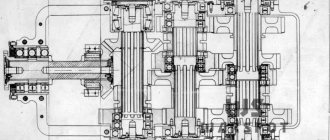
Engine and transmission of the KV-1 tank
The KV-1 tank was equipped with a 12-cylinder four-stroke uncompressor diesel engine V-2K. Maximum engine power is 600 hp. With. at 2000 rpm, operational - 500 l. With. at 1800 rpm. Cylinder diameter 150 mm. The piston stroke of the left group is 180 mm, the right one is 186.7 mm. The cylinders were arranged in a V-shape at an angle of 60°. Compression ratio 14 - 15. Dry engine weight with electric generator without exhaust manifolds - 750 kg.
Fuel - diesel, DT grade or gas oil grade "E"; it was supplied forcibly using a twelve-plunger fuel pump NK-1. The total filling capacity of the fuel tanks was 600 - 615 liters. Two tanks were installed on the right side of the tank hull: the front one in the control compartment, the rear one in the fighting compartment. The filling capacity of the front tank was 230 - 235 l, the rear - 235 - 240 l. The third tank with a capacity of 140 liters was installed on the left side of the tank hull in the fighting compartment. To increase the supply of transportable fuel, at the end of the summer of 1941, three to five additional fuel tanks began to be installed on the fenders of tanks. On tanks produced by LKZ, the tanks were rectangular in shape, while those produced by ChKZ were cylindrical. External fuel tanks were not connected to the engine power system.
The lubrication system is circulating, under pressure. Oil circulation was provided by a three-section gear oil pump. Oil tank capacity - 60 l. Aviation oils were used to lubricate the engine: MK and MS in summer and MZS in winter.
The cooling system is liquid, closed, with forced circulation. There are two tubular radiators, installed on both sides of the engine, tilted towards it, with a total capacity of 55 - 60 liters.
To clean the air entering the engine cylinders, the tank was equipped with a Pomon-type centrifugal air cleaner with an oil bath and a wire filter (gimp).
The engine was started using two SMT-4628 electric starters with a power of 4.4 kW each or with compressed air from two air cylinders. Since the end of 1941, instead of two SMT-4628 starters, the KV-1 began to be equipped with one ST-700 starter with a power of 11 kW.
The mechanical transmission consisted of a multi-disc main ferodo dry friction clutch on steel, a five-speed twin-shaft gearbox with five forward gears and one reverse gear, multi-disc steel-on-steel dry friction side clutches with band floating brakes and two planetary double-row final drives.
T-35
| T-35 | |
| TTX/Tank brand | issue 1939 |
| Combat weight, kg | 54250 |
| Crew, people | 11 |
| Size, mm | |
| Total length | 9740 |
| Width | 3200 |
| Height | 3440 |
| Clearance | 530 |
| Track width | 525 |
| Armament | |
| Guns, pcs. x cal. | 1x 76.2 mm CT |
| 2x 45 mm 20K | |
| Shells, pcs. | 76.2 mm - 96 |
| 45 mm - 226 | |
| Machine guns, pcs. x cal. | 6x7.62 mm |
| Machine gun type | DT |
| Cartridges, pcs. | 10080 |
| Armor thickness, mm | |
| Vert. housing | 70-30-20 |
| Horizon housing | 20-10 |
| Tower | 35-30 |
| Engine | |
| Type | 4t/12ts/k/zh |
| Brand | M-17T |
| Power max., hp | 500 |
| At rpm | 1800 |
| Gearbox transmission | 4/1 |
| Speed max., km/h | 30 |
| Fuel type | Gasoline 1 s |
| Capacity tank, l | 910 |
| Cruising range, km | |
| - highway | 140 |
| - country road | 100 |
| Obstacles to be overcome | |
| Ud. pressure, kgf/cm2 | 0.86 |
| Rise, deg. | 25 |
| Descent, deg. | 30 |
| Roll, deg. | 15 |
| Ditch, mm | 4400 |
| Wall, mm | 1200 |
| Brod, mm | 1700 |
Chassis of the KV-1 tank
As applied to one side, it consisted of six small-diameter road wheels with internal shock absorption and three rubberized support rollers. From July to August 1941, ChKZ organized the production of cast track and support rollers without depreciation.
The suspension of the road wheels is individual torsion bar.
The drive wheel consisted of a cast hub and two cast removable rims with 16 teeth each. The guide wheel was installed on the crank axis of the screw track tension mechanism.
The 700 mm wide track included 87 - 90 tracks with a pitch of 160 mm. The track was a stamping made of 35ХГ2 steel with two rectangular windows for lantern engagement with the teeth of the drive wheel. Since the fall of 1941, cast tracks have been produced.