History of creation
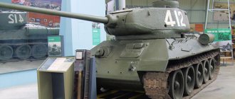
The history of the creation of this modification goes back to development at the end of 1942. project of the T-43 tank, which was supposed to be a replacement for the T-34. But radical changes in the design of the T-34 led to a sharp increase in weight and affected the maneuverability of the vehicle, which was unacceptable. Back in April 1943. it was known that the 76 mm T-34 cannon could penetrate the armor of the latest German Tiger tanks from less than 500 m. Subsequently, the insufficient effectiveness of the 76-mm cannon had a strong impact during the Battle of Kursk, where victory was achieved at the cost of huge losses. Therefore, in May 1943, the State Defense Committee decided to strengthen the artillery armament of the tank by installing a 52-K anti-aircraft gun on it, which could penetrate the frontal armor of the Tiger from a distance of 1000 m. Although work to strengthen weapons had been carried out since the beginning of 1943. By mid-1943 Four variants of 85 mm guns were submitted to the competition. It was won by the S-53 cannon, created at the TsAKB under the leadership of chief designer V.G. Grabina. But in order to accommodate it and ensure normal operation of the crew, it was necessary to enlarge the turret of the T-34 tank of the 1942 model. In addition, the tests revealed some design flaws of the S-53. In order not to delay the work on rearmament of the tank, it was decided to install the already produced 85-mm D-5T cannon in an enlarged turret developed at the design bureau. Outwardly, it was similar to the turret of the experimental T-43 tank, like the turret developed at plant No. 183 in Nizhny Tagil. By GKO Decree No. 5020ss, dated January 23, 1944, the tank was adopted by the Red Army under the designation T-34-85. After modifications and the start of mass production of the S-53 gun, in March 1944, plant No. 183 switched to the production of T-34-85 tanks. Then the S-53 gun began to be installed on Gorky and Omsk vehicles. In fact, after this modernization of the T-34, a new tank was obtained, which was successfully used in all battles of the final stage of the war. In the post-war years, the T-34-85 was produced under license in Poland and Czechoslovakia; in total, more than 35,000 vehicles were produced. The T-34-85 was the main tank of the Soviet Army until the mid-fifties. Officially, the T-34-85 tank was removed from service in the Russian Federation only in 1993. After the end of the Great Patriotic War, the tank was supplied to many countries around the world and took part in not a single armed conflict. It was used during the Korean War, several wars in the Middle East, and the Vietnam War.
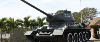
I present to you two photos of a Walkaround review of the T-34-85 tanks, side number 507 and side number 750, located in an open area in the exhibition of the Panorama Museum of the Battle of Stalingrad in the city of Volgograd. Photos were taken in September 2006. They, like many other photos, were used by me when building prefabricated models of the T-34-85 from Revell and UM. I hope my photographs will help you when building models at various scales.
CRADLE
The cradle (Fig. 54) has a cylindrical shape. Inside the cradle 1 there are three bronze ring linings: the front middle 3 and the rear 4, which serve as guides for the gun barrel. In the middle part of the cradle there is a square flange to which the armor is attached. On the sides of the cradle there are trunnion sockets with pressed-in bronze bushings 5. The trunnions fit into the bushings and are attached with their sides to the turret brackets of the T-34-85 tank. On the right side of the cradle, bracket 6 is attached for installing a DTM machine gun and the right fencing shield. On the left side of the cradle, bracket 7 of the sight, sector 10 of the lifting mechanism and the left shield of the fence are attached.
Rice. 54. Cradle
| Click on the picture to enlarge | |
Near the sector of the lifting mechanism there are two sockets 11 for stopping the traveling position of the gun. The gun can be mounted stowed in two positions: at an elevation angle of 0° and at an elevation angle of 16°. A key 8 with bronze lining is attached to the top of the cradle, giving direction to the barrel during rollback and keeping it from turning when fired. At the bottom of the cradle there is a beard boss 12 with two holes in which the rods of the anti-recoil devices are attached. Rubber buffers 9 are attached to the end of the cradle on both sides, softening the impact when rolling.
COLLECTION DEVICES
Fig.55. Rollback brake
| Click on the picture to enlarge |
Recoil devices consist of a rollback brake and a knurler. The recoil brake serves to absorb the energy of the recoil parts when fired. The knurl serves to return the recoil parts to their original position after the shot. The recoil brake and the knurl are placed in a common holder 4 (Fig. 49), which is bolted to the breech.
Recoil brake device
The recoil brake is hydraulic spindle type. It is filled with 3.65 liters of glycerin liquid Steol Steol M (for a brake without compensator). The recoil brake is located in the left cage socket. It consists of the following main parts (Fig. 55): cylinder 1, rod 3 with piston 2, spindle 4 with moderator 5 and oil seal housing 6 with oil seal.
Knurling device
Fig.56. Knurl
| Click on the picture to enlarge |
The knurl is hydropneumatic. It is filled with 3.15 liters of glycerin liquid steol or steol M and air. compressed to 34-37 kg/cm2. The knurl is placed in the right socket of the clip. It consists of the following main parts (Fig. 56): outer cylinder 1, working cylinder 2 and rod 3 with piston.
CANNON GUARD
The cannon fencing protects the crew of the T-34-85 tank from being hit by recoil parts while firing the cannon.
It consists of two shields mounted on the cradle on the right and left sides, and a sleeve catcher. On the right shield of the fence there is a copier and a bracket for blocking device No. 52 (Fig. 57). On the left shield of the fence there is an electromagnet for 2 electric releases, a side level, a rollback indicator and a lever for 1 electric release with a cord for manual release. At the bottom, the right and left shields of the fence are connected by a bracket, which gives rigidity to the fence and, in addition, serves to secure the axis of the sleeve catcher in it. Fig.57. Trigger
| Click on the picture to enlarge |
The sleeve catcher can occupy two positions: traveling, when it is raised up; combat when it is lowered to a horizontal position. In the stowed and combat positions, the sleeve catcher is fixed with a stopper located on the left side of the sleeve catcher. To release the sleeve catcher, you need to pull the stopper ring towards you. A sleeve deflector and a guide tray, which serves to guide the cartridge during loading, are attached to the rear wall of the cartridge case. The tray is hinged to the sleeve catcher and held in the upper position by a spring.
TRIGGER
For firing the cannon there is an electric trigger and a manual trigger.
For firing from the DTM machine gun, coaxial with the cannon, there is an RT-9 electric trigger. The electric release of the tank gun (Fig. 57) consists of an electromagnet 2, a locking device No. 52-6, a release lever 1, a pressure 17 with a spring 9, a ring with contact 20 on the lifting mechanism, toggle switches for the gun 4 and machine gun 3, a fuse for 20 and electrical wiring systems. Electromagnet 2 is mounted on the left shield of the fence. It consists of a coil and a core. Fig.58. Lifting mechanism
| Click on the picture to enlarge |
Blocking device No. 52 is mounted on the bracket of the right guardrail. It consists of a body with a cover 5, an axis 7 with two levers 10 and 13, a latch 14 with a spring 9, a rod 11 with a button 12 and a cap 8 with a contact ring. The release lever is attached to the left fence panel. A regulating screw is screwed into the trigger pressure to adjust the electric trigger of the gun. The toggle switches for the gun of the T-34-85 tank and the coaxial machine gun are installed on a panel attached to the body of the lifting mechanism.
When the toggle switches are in the lower position, the electric release circuit is turned off; when in the upper position, it is turned on. The 20 A fuse is located on the panel in the tower on the left side. If the gun's electric trigger does not work, you can fire a shot with a manual trigger, that is, pull the trigger cord down. The electric trigger of the RT-9 machine gun consists of an electromagnet, a double-arm lever with a finger, two grips, a trigger axis and fastening parts. To fire a shot from a machine gun, you need to turn on the right toggle switch and press the trigger lever.
LIFTING MECHANISM
The lifting mechanism serves to give the tank cannon and the coaxial machine gun the required elevation and descent angles.
The lifting mechanism (Fig. 58) consists of a housing 2, a spur gear 1, a worm wheel 5, a worm 10 and a gear sector mounted on the cradle. The lifting mechanism housing consists of two halves connected to each other with bolts 4. The housing is attached to the left tower bracket with bolts. Bushings 3 and 7 are pressed into the central holes of both halves of the crankcase, serving as bearings for the spur gear shaft. The crankcase hole is closed with a threaded cap 8. Fig.59. Gun travel position stopper
| Click on the picture to enlarge |
Spur gear 1 is in mesh with a gear sector mounted on the cradle. The gear is held against axial displacement by an adjusting nut 6 with a locking ring 9. The worm wheel is placed with its hub on the splines of the shaft of the cylindrical gear 1 and is held on the shaft by a nut 6. The worm 10 is placed in the crankcase boss and is engaged with the worm wheel. The worm axis rotates in bushings 21 and 22, inserted into the sockets of both halves of the crankcase.
A nut 20 is screwed onto the worm axis between the lifting mechanism housing and the drive handwheel, which is used to select the axial play of the worm. If there is a large axial play of the worm, you need to remove the cotter pin from the nut and turn it slightly, without disturbing the smooth engagement of the worm pair, after which the nut is secured with a cotter pin. At the end of the worm shaft, a handwheel 15 is mounted on a key.
When the handwheel rotates, the worm rotates, which transmits rotation to the worm wheel and spur gear 1. The spur gear, rolling along the sector of the lifting mechanism, causes the cradle with the barrel to rotate around the axles in a vertical plane. The left bracket of the tank turret houses the gun's travel position stopper (Fig. 59). Using a stopper, the tank's gun can be secured in two positions: at an elevation angle of 0° or at an elevation angle of 16°.
Content
T-34-85 tail number 507
1
Combat use
The first T-34s, armed with an 85 mm gun, began to be delivered to the armored units of the Red Army at the end of the winter of 1944. One of the first combat units equipped with the modernized T-34 was the 38th separate tank regiment. The towers were painted with inscriptions “Dimitri Donskoy”; they were made with funds provided by the Russian Orthodox Church. In total, the regiment consisted of 21 units; in addition to the T-34-85, the regiment consisted of flamethrower versions of the T-34-76.
As part of the 58th Army, the tank regiment conducted combat operations on the territory of Ukraine. Another unit equipped with new equipment with a D-5T cannon was the 119th Tank Regiment. Since the tank was made with money collected from the residents of the Republic of Armenia, inscriptions in the national language “David of Sassoun” were written on the tank turrets, in honor of the hero of the republic. The regiment took part in hostilities as part of the 2nd Ukrainian Front.
In the early spring of 1944, the modernized “thirty-fours” began to be sent to tank brigades, as well as to tank and mechanized corps. Thus, the 2nd, 6th, 10th and 11th Tank Corps received new equipment. When forming the crews of new vehicles, a problem arose in the presence of a 5th crew member. The issue was resolved by staffing the tank crews with soldiers from the anti-tank rifle company.
New vehicles were primarily supplied to the best combat formations of the Red Army.
At the same time, the crews were given only a few hours to master the new tanks. Widespread use of the T-34-85 occurred in battles in Right Bank Ukraine, especially during the crossing of the Dniester.
In clashes with enemy armored vehicles, the new equipment performed well, but was still inferior to heavy German tanks. The 88 mm guns of the Tigers had high armor-piercing power, especially since the armor protection of the hull of the T-34s did not change, and in terms of power, the 85 mm gun of the Soviet tank was slightly inferior to the German 88 mm.
Also, T-34s with the 85th D-5T artillery system in the amount of 23 units in the early spring of 1944 entered service with the 7th Separate Guards Red Banner and Order of the Red Star Novgorod Tank Brigade, which led the offensive as part of the Karelian Front. The brigade also included 42 T-34s with a 76 mm gun and 10 Valentine IXs.
The offensive was successful, especially since the enemy (Finnish and German combat formations) had practically no tank units. With the liberation of Kirkenes in Norway, the front was disbanded.
During the offensive Operation Bagration in the summer of 1944, T-34-85s occupied most of the Red Army's armored fleet. Thus, of the 811 T-34s participating in the offensive, vehicles armed with the 85 mm artillery system accounted for more than 50% of the tank fleet.
The largest number of new “thirty-fours” took part in the offensive operations of the Red Army in 1945. The 3rd TA of General P.S. Rybalko participating in the Vistula-Oder offensive operation. had on its staff 640 T-34-85 tanks, 22 T-34-76 tanks (used as minesweepers), as well as IS-2 heavy vehicles (21 units) and self-propelled artillery units (63 ISU-122 units, 63 units SU-85, 63 units SU-76 and 49 SU-57I).
In the battles for Berlin, the T-34-85 faced a very big problem, namely the widespread use of faust cartridges by the enemy.
Ease of production and use, as well as combat in urban conditions - all this made the Faustniks another dangerous opponent of Soviet tankers in the battles for the capital of the Reich.
In order to somehow protect their vehicles from shots from hand-held anti-tank grenade launchers, the crews hung various devices on their tanks. But, despite the active use of grenade launchers in battles, most of the T-34-85’s losses were caused by enemy artillery.
In the battles with Japan in the summer of 1945, 670 T-34-85 tanks took part, and along with them, the armored units of the Red Army operating against Japanese units included obsolete models T-26 and BT-7. The main striking force was the 6th Tank Army, its fleet consisted of 408 brand new T-34-85s, which arrived from two factories: No. 174 and No. 183.
A small number of "thirty-fours" were captured by German troops and their allies and were later used by them, for example by formations of the SS Wiking division. At the end of the war, T-34-85 also entered the armies of the USSR's allies (Poland, Yugoslavia, Czechoslovakia), and later to the countries that were part of the Warsaw Warsaw War.
