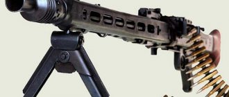
Single Belgian machine gun FN MAG
The development of a single MAG machine gun (Mitrailleuse a Gas - “gas system machine gun”, another option - Mitrailleuse d'Appui General - “general purpose machine gun”) was launched in the early 50s at FN. The head of the work was the chief designer M. Ernest Vrevier. As a basis, we took the locking and automatic system, the fastening of a replaceable barrel and the recoil absorber of the Browning light machine gun, which was previously produced by FN, and the belt feed system of the MG42 machine gun (Germany). The result was a machine gun that was recognized as one of the best and remains so to this day.
BAR light machine gun, from which MAG borrowed the automatic and bore locking system
In the breech of the barrel there is a thread that serves to fasten it to the coupling. A lock that secures the clutch and prevents it from turning is installed in the receiver on its left wall. The base of the carrying handle is attached to the barrel coupling flanges. The barrel is locked in the receiver by turning the handle. The handle in this position does not cover the aiming line. Another important legacy of World War II is the use of spot welding, stamping and riveting without sacrificing reliability. The receiver is assembled from parts made from stamped steel sheets and fastened with rivets. At the same time, some critical parts are still made from steel blanks by milling. The design turned out to be very heavy, but had high strength. In the front part, the structure was reinforced to install the barrel coupling, in the rear - to install the damper and butt. The guides for the bolt frame and bolt are protrusions on the inner walls of the receiver. The receiver has several holes: a cutout for moving the bolt handle in the right wall, and a window for ejecting cartridges in the lower part.
Single FN MAG machine gun on a tripod machine
The bore was chrome plated. The gas outlet unit includes a gas regulator and is located under the barrel. Powder gases enter the cylindrical coupling of the regulator. The gas piston moves inside it. The coupling has three outlets. When firing from a cold and cleaned weapon, almost all powder gases escape through these holes, and only the minimum required amount of gases is used for automatic operation. Heating of automation parts, the ingress of sand, the formation of soot, and the like increase the friction force, necessitating an increase in the pressure of the powder gases. To do this, you need to turn the gas regulator lever, after which the gas coupling moves along the gas chamber, sequentially closing the outlet holes. Powder gases in a larger volume begin to flow to the gas piston. This device makes it possible to regulate the rate of fire in the range from 600 to 1000 rounds per minute. A flash suppressor with slots and a front sight are installed at the muzzle of the barrel.
The layout of the locking unit and gas exhaust system is an “inverted” Browning design, since his machine gun had a box magazine inserted from the bottom, and the MAG’s tape receiver was located on top. The gas piston is connected to a rod, which has a window for ejecting the cartridge case. The bolt carrier (its rear part) is a massive strut, which is connected to the locking lever linkage, which is connected to the locking lever. Half of the locking lever is located in cutouts on both sides of the bolt body. The firing pin is mounted inside the bolt, the ejector is mounted on the mirror. A return spring is installed inside the piston rod. To ensure proper operation, increase reliability and extend service life, springs began to be made in multiple rows. The recoil absorber consists of a bushing that receives the impact of the bolt frame, which, when moving backwards, fits into a shock-absorbing cone. The cone, together with the bushing, moves smoothly back and passes through eleven disc spacers that accumulate the energy of the bolt frame. During the reverse movement, the gaskets forcefully push the bushing and cone forward.
Like most machine guns, the shot is fired from an open bolt. When the fire ceases, the bolt remains in the rear position, the cartridge remains in the belt link. After the last shot is fired and there is no cartridge in the chamber, the bolt does not move from the forward position. The trigger mechanism was also based on the MG42. The trigger is mounted on the axis in such a way that its back part rises when pressed, pushing the front shoulder of the sear, its rear shoulder drops, disengaging from the cocking mechanism. In this case, the bolt is released and moves forward under the influence of the return spring. There is a disconnector on the top of the trigger, which gets in the way of the movement of the piston and bolt. The disconnector lever is spring-loaded, its front side has a protrusion. When the trigger is pressed, the tail of the sear rises, and the disconnector lever moves forward under the action of a spring, blocking the sear. If the trigger is not pressed, the disconnector lever rises, holding the sear in such a way that it cannot engage with the cocking mechanism. The protrusion of the disconnector lever again becomes in the way of the bolt. The gas piston, moving away, presses on the lever and compresses its spring. The nose of the sear goes up and the tail goes down. The piston rod, passing over the sear, comes into contact with the entire area of the upper surface of the sear, thereby eliminating the appearance of deformations and nicks. To prevent a spontaneous shot due to a breakdown from the sear, machine guns of the latest series are equipped with a sear with a pair of protrusions, accordingly making the piston rod cocking two-stage.
FN MAG GPMG
The push-button fuse is made in the form of a beveled rod. If the fuse is pressed to the right (the “SAFE” position), it is located under the tip of the sear, preventing it from going down; when the fuse is pressed to the left (the “FIRE” position), it turns its cutout towards the sear, allowing it to go down.
The ammunition used is a single 7.62mm NATO cartridge mounted in an American M13 type link belt. A metal belt with a capacity of 50 rounds can also be used, however, these two types are not interchangeable; a replacement receiver is required.
C6: MAG modification for the Canadian Armed Forces
The sector sight has a notch in increments of 100 meters. When the rail is in the folded position, shooting is ensured at a distance of 200-800 m, when folded (that is, in the rack-mount version) - 800-1800 meters. The diopter, which is used in the folded position, and the rear sight, which has a triangular slot, are made on a movable clamp. To adjust the front sight vertically, it is lifted by the safety bracket and rotated. After this, the bracket is put in place. Horizontal adjustment is carried out by moving inside the frame of the front sight itself. For such adjustment, a special key is required. To fire at night, luminous Trilux attachments were installed on the sight and front sight, but later they were replaced with special night sights.
The tape is a metal link tape with an open link. Loose cartridge belt was loaded only in factory conditions. Equipping a non-separable 50-round belt with cartridges is possible even in the field. It is possible to connect the tapes together, which ensures continuous firing. A box for 50 rounds is mounted on the left side of the machine gun, and a box for 250 rounds is placed next to it.
To cock the machine gun, the cocking handle is pulled all the way back and then returned to the forward position. Only after this does the safety move to the “SAFE” position, and the letter “S” becomes visible on the right side of the bolt. The machine gunner, pressing two latches located on the back of the upper cover of the receiver, raises it to a vertical position. After this, the tape is inserted across the receiver tray, with the open part of the links facing down. The first cartridge is located on the right opposite the latch. The lid comes down. The safety lever is moved to the “fire” position (“F”). When the trigger is pressed, the nose of the sear is lowered, and the bolt frame, together with the bolt, begins to move forward under the action of the recoil spring. The protrusion located at the top of the power system pushes the first cartridge out of the belt.
The locking lever moves down under the action of the bolt. The cartridge is sent into the chamber, the ejector engages with the groove of the sleeve, and the bottom of the sleeve enters the recess of the shutter mirror. The ejector, compressing the spring, moves back, and the bolt stops. At the same time, the gas piston rod and bolt frame continue to move. In front of the combat stop, located at the bottom of the receiver, the locking lever is lowered. With further forward movement of the rod, the locking lever rotates and the bolt is locked. At the last stage of movement, the protrusion of the bolt frame hits the firing pin and a shot occurs.
FN MAG installed in the doorway of the Eurocopter EC 725 Cougar MkII helicopter presented in 2007 at the Le Bourget air show.
Part of the powder gases is supplied to the gas regulator, after which the gas piston moves back. The locking lever linkage begins to rotate again and, as the rod moves, it disengages the lever and the locking stop of the box. The locking lever moves the bolt and the ejector removes the cartridge case. The connection between the piston rod and the locking lever through a swinging slide at a high rate of fire softens the shock, making the operation of the locking system more reliable and smoother. The ejector moves the sleeve towards the hole made in the piston rod. From there it is thrown out through a window in the bottom of the receiver. The bolt frame, moving backward, compresses the return spring, after which, hitting the shock absorber, it moves forward. If the trigger is pressed, the cycle repeats.
A two-stage feed system, the design of which was borrowed from the German MG42 machine gun, ensures uniform advancement of the belt while the bolt moves in both directions. On the top of the shutter frame there is a spring-loaded roller that fits into a shaped groove in the receiver cover. There is a hinge at the back, and the front is connected to a short lever. This lever swings in such a way that when one arm moves towards the axis of the barrel, the other leaves the groove. There is an inner feeder finger on one shoulder, and two outer ones on the other. Thus, while the shutter was moving forward, the roller entered the straight section of the groove; after capturing the cartridge, it passed into the curved part, moving to the right and deflecting the lever to the left. In this case, the inner finger of the feeder grabs the cartridge, and the outer fingers push it forward relative to the longitudinal axis of the machine gun by half its length. As the shutter moves backward, the roller turns to the left along the groove. The lever goes to the right so that the inner finger advances the tape half a step. In this case, the first cartridge stops at the latch, ready for chambering. The next cartridge is engaged with the outer pins.
An American Marine fires from an L7A2, a British modification of the MAG.
The machine gun is equipped with a bipod in front of the gas cylinder, which rotates in the transverse plane and allows firing from a slope without violating the aiming line.
The machine is a folding tripod equipped with vertical and horizontal guidance mechanisms. To reduce mechanical loads and reduce recoil, FN has developed a so-called “soft” machine design, in which a shock-absorbing device is used to secure the machine gun in the machine cradle. For the MAG machine gun, Denmark has developed several models of lightweight DISA tripod machines.
FN produced three main series of MAG: 15 modifications of the single Model 60-20 machine gun, tank Models 60-40 and aircraft Models 60-30. The latest models do not have bipods, stocks, or their own sighting devices. Tank modifications of the MAG were introduced in some countries instead of other machine guns - for example, in the Dutch army on the German Leopard 2 tanks instead of the anti-aircraft MG3. The Model 10-10 was also developed with a shortened stock and barrel (the so-called “jungle model”), but it did not find demand. For special-purpose units, a twin vehicle installation with a separate or single descent was created.
M240E1, MAG modification for the US Army, installed on the LAV-25
To replace the barrel, you need to turn the safety lever to the right to the “SAFE” position, while the bolt should be in the rear extreme position. If the weapon is unloaded, it must be cocked. It is not necessary to unload the weapon. The handle latch is inserted into the groove of the barrel coupling, the head of the barrel lock located on the left side of the receiver is recessed, and the carrying handle is tilted to a vertical position and removed forward. After this, the trunk is separated forward. To install the barrel, you need to hold the handle vertically, place the barrel on the protruding part of the gas chamber, and then push it back. The gas regulator goes into the gas chamber, and the sector rifling of the barrel goes into the sector slots of the coupling. After this, you need to turn the handle to the right and engage the barrel with the clutch. The barrel will be automatically locked by the lock.
Although the MAG is clearly too heavy for use as a hand gun with its “body” weight of 11 kilograms, it has earned popularity for its high shooting accuracy and reliability. It is in service in many countries of the world, including: Argentina, Belgium, Canada, Cuba, Ecuador, India, Indonesia, Israel, Kuwait, Libya, Malaysia, the Netherlands, New Zealand, Peru, Qatar, Sierra Leone, Singapore, South Africa , Sweden, Tanzania, Uganda, Great Britain, Ireland, USA, Venezuela, Zimbabwe and many others. In total, more than 75 countries purchased about 150 thousand machine guns. A 6.5 mm modification of the M58 was supplied to Sweden. The MAG machine gun is produced under license in the UK (in service under the designations L7A1 and L7A2), India, Israel, Ireland, USA, Sweden, South Africa, Singapore (with a lightweight barrel under the designation “Type 74”) and in Taiwan. Machine guns produced abroad have some differences - primarily in the controls. The largest number of machine guns was manufactured in the United States, where it, under the designation M240, is installed on infantry fighting vehicles (M240S), tanks (M240T), armored personnel carriers and helicopters (on pivot mounts, M240E1). The M240 device corresponds to the latest modifications of the Model 60-40 powered by American-made M13 tape.
A US Marine fires an M240G mounted on a tripod.
Regarding the 7.62x51 NATO cartridge, it must be noted that it does not have enough energy as ammunition for a single machine gun, and its approval as a standard NATO cartridge to date seems very strange. But over the past 50 years, the cartridge has been perfectly mastered in production in a number of countries and continues to retain its importance. Most often, the cartridge has a brass sleeve, less often a steel one. 7.62x51 NATO is equipped with all acceptable bullets - ordinary, tracer (mainly these two types are used when firing from MAG), armor-piercing, and so on. The same FN created the SS123 bullet for this cartridge, which is similar in design to the SS109 bullet from the 56 mm cartridge. The mass of SS123 is 9.6 grams, the initial speed is 865 m/s. Thanks to the presence of a hardened steel core, the armor penetration of the bullet is 1.5 times higher than that of the standard NATO cartridge.
Type 74 machine gun, Taiwanese modification of MAG
The procedure for unloading a single FN MAG machine gun
By pressing the latch in front of the sight stand, tilt the receiver cover up. If there is tape, remove it, inspect the guide groove, and close the lid. Pull the cocking handle back to remove the cartridge from the chamber, press the trigger, holding the handle in the rear position, return it to the forward position.
Technical characteristics of the single FN MAG machine gun:
Cartridge - 7.62x51 NATO; Machine gun weight – 10.85 kg (with bipod and butt); Machine gun weight - 21.35 kg (on a tripod); Barrel weight – 3.0 kg; Machine gun length – 1260 mm; Barrel length – 545 mm; Rifling – 4; Rifling stroke length – 305 mm; Sights – sector sight, front sight; Initial bullet speed – 840 m/s; Rate of fire – 600-1000 rounds per minute; Combat rate of fire - 200 rounds per minute; Sighting range – 1800 m; Effective fire range – 1200 m; Belt capacity – 50 or 250 rounds.
FN MAG mounted on the turret of a Mexican tank
Australian soldier with MAG 58 during the Indonesian-Malaysian confrontation (1963-1966)
A Naval Mobile Construction Battalion sailor fires an M240B mounted on the turret of an Army HMMWV, 2004, Iraq.
A US Navy soldier fires an M240 from a helicopter. Pacific Ocean, 2003
An American soldier fires an M240 with a telescopic sight. Baghdad, 2007
An American soldier fires an M240 mounted on a tripod. Afghanistan, 2008
Principle of operation
Weapon automation operates according to a widespread scheme that uses the energy of powder gases removed from the barrel. The gas mechanism is equipped with a regulator having three outlets. When firing from a cleaned and cold weapon, most of the powder gases escape through these holes to the outside, and the remaining amount is sufficient to ensure reliable operation of the automation. When it becomes necessary to increase the pressure of the powder gases (to overcome the frictional force in heated parts, in cases of soot formation or dirt ingress), by turning the gas regulator lever, you can sequentially close the holes. Also, such a device allows you to adjust the rate of fire within the range of 600-1000 rounds/min.
Modifications
In addition to the basic model, a variant was produced for airborne troops under the designation Para - its barrel was shortened to 349 mm, and the stock was made retractable. The version adopted by the US troops received the M249 index.
The weapon differs from the original Belgian model in the use of a plastic stock and a heat-protective barrel casing, the second position of the gas regulator has been eliminated.
The weight of the M249 increased to 7.5 kg, so further attempts were made to reduce the weight. For example, by replacing plastic cartridge boxes with fabric bags.
The M249 SPW variant, created for special forces, lost its magazine supply and mounting for installation on vehicles. Several Picatinny rails were added for mounting various accessories. The SPW barrel is shorter than the standard one (406mm), but longer than the “landing” one.
A later Mk. 46 differs from the SPW in having a reinforced (but not lengthened) barrel and a plastic butt instead of a retractable element.
The Mk.48, created out of the need for a compact but more powerful machine gun, was chambered for 7.62x51mm. The newest weapon model, the Mk.3, has an adjustable stock, a removable barrel shroud and the ability to change caliber from 5.56mm to 7.62mm.
In service
The FN MAG bullet is in service in almost 80 countries around the world and is produced under license in 10. The largest number of machine guns are produced in the USA, where under the M240 brand it is installed on the main types of military equipment. According to some reports, they even began to replace the M60 in service with a machine gun of this brand. From 1958 to the present, about 200,000 copies of the FN MAG have been produced.
FN MAG installed in the doorway of a combat helicopter
Production[edit]
- Argentina - produced by Dirección General de Fabricaciones Militares under the symbol Tipo 60-20 MAG
. - Belgium - produced by FN Herstal.
- UK - produced by Manroy Engineering.
- Egypt - produced by Maadi under the designation Helwan 920
. - India - produced by Indian Ordnance Factories.
- Indonesia - produced by Pindad under the designation SM2 V1
. - Nigeria - produced by DICON.
- China - produced by Norinco for export under the designation CQ7.62
. - USA - produced by FNH USA (at a plant specially built for these purposes in 1980-1981 in Columbia, South Carolina), US Ordnance (assembly line in Reno, Nevada) under the symbol M240
. - Republic of China (Taiwan) - produced under the designation Type 74
. - Sweden - produced by Bofors Carl Gustaf under the symbol Ksp 58
.

