The Kalashnikov tank machine gun (PKT) is the most powerful automatic weapon of the USSR, created to suppress and destroy enemy personnel and has proven itself in several armed conflicts of the 20th century. This rifle unit is still installed on tanks, armored infantry vehicles and other military equipment (BMD, BTR, MT-LB, BRDM) both in the Russian army and abroad.
Variations
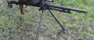
The infantry (also called manual) version is used when installing a bipod (PC). To use it as a heavy machine gun, the installation of an appropriate machine tool (PKS) is required. To use a weapon as a weapon on an armored personnel carrier (APC), it is mounted on special devices. The same thing happens when using a machine gun in a tank turret (PKT).
By the way, an interesting fact is that not only the easel, but also the infantry version can be used to neutralize the threat from the air.
Tactical and technical characteristics of PC, PKM, PKT and PKP
| option | PC | RMB | PCT | PKP |
| Weight (kg) | 9,0 | 7,5 | 10,5 | 8,2 |
| Barrel weight (kg) | 2,6 | 2,4 | 3,23 | — |
| Length (mm) | ||||
| Barrel length without flash suppressor (mm) | ||||
| Initial bullet speed (m/s) | ||||
| Rate of fire (rounds per minute) | ||||
| Practical rate of fire (rounds per minute) | ||||
| Weight of a box with loaded belt for 100, 200 or 250 rounds (kg) | 3,9/8,0/- | 3,4/6,2/- | -/-/9,4 | 3,9/8/- |
Machine
| Option | 6T2 | 6T5 |
| Weight (kg) | 7,5 | 4,5 |
| Sight angle, ° | from −15 to +15 | from −10 to +20 |
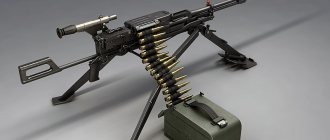
Rice. 3.24. General view of Kalashnikov machine guns:
a — machine gun on a bipod (PC); b- machine gun on a machine (PKS); c — tank machine gun (PKT);
g – machine gun “Pecheneg” (PKP)
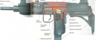
The machine gun consists of the following main parts: barrel; receiver with lid, receiver base and butt 2 (for PK and PKS machine guns); bolt frame with extractor and gas piston 3; shutter 4; return spring 5 with guide rod 6; gas piston tubes 7 (for PK and PKS machine guns - with a bipod); trigger 9; electric trigger 8 (only for the PKT machine gun}.
The machine gun kit includes boxes with tapes, an accessory belt and a case (for PC and PKS), a spare barrel and a device for dry firing.
Rice. 3.25. Main parts and mechanisms of the machine gun:
a—PC machine gun; b — PKT machine gun; 1 - ramrod; 2 - shutter; 3 — bolt frame with extractor and gas piston; 4 — return spring; 5 - guide rod; 6 — receiver with cover, receiver base and butt; 7 - trunk; 8 — gas piston tube with bipod (for the PK machine gun); 9 — box with tape; 10 - accessory; 11—trigger mechanism; 12 — electric release
Barrel 4 has a gas outlet 3, which communicates with the gas chamber 5. The gas chamber houses a regulator 6, which changes the amount of powder gases acting on the bolt frame piston. The PK machine gun regulator operates on the principle of releasing some of the gases into the atmosphere through variable holes, and the PKT machine gun operates on the principle of changing the amount of gases diverted to the piston due to grooves of varying depths on the regulator rod. The regulators have three fixed positions.
A handle is attached to the barrel of the PKT machine gun. In the handle holder there is a slider, which, when the handle is raised, rests against the receiver and ensures the initial shift of the barrel when disassembling the machine gun. On the outer surface of the PK machine gun barrel there are longitudinal grooves to improve heat transfer and reduce weight.
The rear cylindrical part of the barrel is located in the receiver. The receiver at the location of the breech section of the barrel has lugs and a protrusion with a bevel to ensure the initial shift of the bolt when locking. In the upper part of the receiver there is a longitudinal window, on the sides of which there are bends for guiding the bolt frame and a reflective protrusion for removing the cartridge case. In front of the longitudinal window there is a transverse groove in which a transverse protrusion of the barrel is placed, which ensures adhesion of the barrel to the receiver. The protrusion on the barrel and the groove of the lock are made at a slight angle to the axis of the barrel, which ensures adjustment of the gap between the barrel and the bolt. The position of the contactor relative to the barrel is determined by a screw, which is rigidly fixed between the lower guides of the receiver base. An increased gap between the barrel and the bolt can lead to transverse rupture of the cartridge case when fired. A gap less than normal does not ensure rotation of the shutter when locked.
Rice. 3.26. Barrel: 1 - piston; 2 — bore; 3 - gas outlet; 4 - trunk; 5 - gas chamber; 6 - regulator
On the left wall of the receiver there is a window with a spring-loaded flap for ejecting cartridges.
On the right wall there is a window for the passage of the feeder and lugs in which the axis of the feeder and the shield are attached. The reloading handle moves along the longitudinal groove.
At the rear of the receiver of PKS machine guns there are two shanks for attaching the butt, and at the bottom are attached the pistol grip and trigger box, and a bracket for attaching the box with tape.
For the PKT machine gun, the receiver has grooves in the back for attaching the electric trigger, and in the rear wall there are three holes: the top one for sighting the axis of the barrel bore when aligning the machine gun; secondary - technological; the lower one is for the protrusion of the guide rod. For mounting the machine gun on the installation there are lugs with holes.
The trigger mechanism is fixed at the bottom. For a PK machine gun, the trigger mechanism consists of a trigger lever with a spring, a trigger with an axis and a safety catch. The trigger lever is pressed to the upper position by a spring, and the trigger interacting with it is pressed to the forward position. The trigger lever sear holds the bolt carrier in the rear position. Turning the trigger lowers the sear and lowers the bolt frame from cocking. The safety acts on the trigger lever, preventing it from going down in a certain position.
The trigger mechanism of the PKT machine gun ensures the transmission of force from the electric trigger lever to the sear and contains a kinematically interconnected rocker arm and a cam with axles. The fuse is designed in the same way as in the PC machine gun.
The electric release has a lever with a safety lock for manual release.
The gas piston tube is designed to direct the movement of the bolt frame with the piston and attach the bipod (for the PK machine gun). There are holes (PC) in front for the exit of powder gases.
The bipod (PC) is mounted on a gas tube with its base and has two legs with skids and a spring for spreading. The legs can be folded and secured with a clasp. The ramrod links are attached to the inner cavity of the leg using a movable clamp.
The bolt frame (Fig. 3.27) is connected to the gas piston using an axle. In its channel there is a return spring; at the back there is a 10 stand on which the extractor with hooks is attached. In the rack there is a through channel 12 for the bolt frame; the channel has an annular groove in which the protrusion of the striker is placed, ensuring the advancement of the striker when locking the barrel bore. On the side walls of the bolt frame there are recesses 4, 6 and 7 with inclined upper and lower surfaces interacting with the roller and feeder protrusion. In front of the rack there is a shaped cutout 2, in which the leading protrusion of the bolt is located. At the bottom at the rear there is a combat platoon that interacts with the sear of the trigger mechanism. The bolt frame moves through the longitudinal grooves of the rack along the bends of the receiver.
Annular recesses of the piston improve the sealing of powder gases in the gas chamber nozzle.
The return spring is mounted on a guide rod consisting of two parts, hingedly connected to each other using an axis.
The shutter (Fig. 3.28) consists of a frame, a striker 2 and an ejector 3.
The striker is placed in a longitudinal groove of the frame. Using a protrusion, it is connected to the bolt frame and moves with it after the bolt stops, and the firing pin, moving out of the hole in the front cut of the frame, strikes the cartridge primer.
The front cylindrical cutout 7 of the frame houses the bottom of the sleeve, and cutout 8 houses the ejector 5. The ejector spring 4 presses it against the sleeve.
Rice. 3.27. Bolt carrier with gas piston: a - assembled; b - disassembled; 1 — channel for the return spring; 2 - figured cut-out; 3 - cut for the passage of ejected cartridges; 4 - inclined surface for interaction with the feed roller; 5 — protrusion for interaction with the shield pusher; 6 and 7 - inclined face and groove for interaction with the feeder protrusion; 8 — ledge for the protrusion of the reloading handle; 9 — socket for connection with the gas piston; 10 - stand; 11 — extractor with hooks; 12 — channel for placing the shutter; 13 - longitudinal grooves; 14 — thickening for connection with the bolt frame; 15 — ring grooves; 16 - leading belt
Rice. 3.28. Shutter: a - assembled; b — disassembled; 1 — shutter frame; 2 - drummer; 3 - ejector; 4 — ejector spring; 5 — ejector axis; 6 — axle stud; 7 - cylindrical cutout for the bottom of the sleeve; 8 - cylindrical cutout for the ejector with a spring; 9 — combat ledges; 10 — protrusion (rammer) for sending the cartridge into the chamber; 11 - leading protrusion; 12 - longitudinal groove for the passage of the reflective protrusion; 13 — hole for the ejector axis; 14 — channel for placing the striker; 15 — drummer protrusion
Rice. 3.29. Receiver:
1—receiver base; 2 and 6—shields; 3—receiver cover; 4 - upper fingers; 5—feed finger; 7-feeder shield; 8 — feeder; 9- feeder protrusion; 10 — feeder roller
The receiver (Fig. 3.29) contains parts of the tape feeding mechanism and ensures the movement of the belt with cartridges and the supply of the cartridge during firing from the tape into the receiving window, from where it is sent to the chamber by the bolt.
The receiver consists of a base 1, a receiver cover 5 and a feeder 8. The base and cover are attached to the receiver using an axis and their protrusions direct the movement of the belt with cartridges.
The base has a transverse window in which the feed finger 5 moves, and a longitudinal window for moving the extractor and lowering the cartridge onto the dispensing line.
The receiver cover closes the receiver and, together with the base, ensures the correct feeding of the next cartridge to be captured by the extractor hooks. The upper pins 4 with a spring are fixed in the cover on the axis, holding the tape with cartridges in the receiver, a feed lever with a spring and a feed comb, thanks to which the cartridge is lowered into the receiving window of the base of the receiver. The input and output windows of the receiver are closed with spring-loaded flaps 6 and 2. In the closed position, the cover is secured with a latch.
The PK machine gun has a sight and a rear sight fuse attached to the top of the cover.
The feeder is mounted using an axle in the lug of the receiver. On the lower arm of the feeder there is a protrusion 9 and a roller 10 that interact with the inclined surfaces of the bolt frame. On the upper arm of the feeder, feed finger 5 with a spring is attached to the axis. The spring presses the finger up towards the tape.
To load the machine gun you must: open the receiver cover; lay the tape on the base of the receiver so that the first cartridge of the rim of the sleeve goes behind the hooks of the extractor; close the receiver cover; pull the bolt frame back by the reloading handle until it stops (before cocking). The machine gun is loaded.
When the bolt frame 10 moves backward, the recoil spring 9 is compressed, and the firing pin 5 moves, the protrusion of which is located in the annular groove of the bolt frame post. The extractor hooks 7 remove the cartridge from the tape and move it back. The cartridge, passing under the feed lever 6, lifts it upward. With further movement, interacting with the bevel of the feed ridge 3 and under the pressure of the feed lever, the cartridge is lowered into the receiving window of the base, disconnecting from the extractor hooks.
When the bolt frame is retracted to the free stroke length, the front bevel of its figured cutout, acting on the leading protrusion of the bolt, turns it counterclockwise. The bolt lugs come out from behind the receiver lugs (unlocking occurs), after which the bolt moves back along with the bolt frame.
With further movement of the bolt frame, its inclined surface runs into the feed roller and it rotates around its axis, while the feed finger, resting on the belt link, moves it to the left and installs the next cartridge against the extractor hooks. The upper fingers of the receiver cover allow the next cartridge to pass through and are lowered under the action of a spring, preventing the reverse movement of the belt. The protrusion of the bolt frame acts on the bevels of the pusher, and the flap opens a window for ejecting the spent cartridge case. The trigger lever (sear of the PKT machine gun) moves down under the action of the bolt frame, compressing the spring. After cocking, the trigger lever (sear) rises under the action of a spring and prevents the reverse movement of the bolt frame (the bolt frame is cocked). The protrusion of the bolt frame releases the pusher, and the flap closes.
To open fire, you must press the trigger (electric trigger button or trigger lever).
When the safety lever is moved to the “Fire” position, its wide cutout will be under the trigger lever (sear) and will allow it to move down.
The trigger hook presses the trigger lever and removes the sear from under the cocking bolt frame. Under the action of the recoil spring, the bolt frame with the bolt rushes forward.
The bolt rammer pushes the cartridge out of the receiving window of the receiver base and. sends it to the receiver.
The bolt frame, with its lower right inclined surface, acts on the feeder protrusion and turns it clockwise, while the feed finger jumps over the next link of the belt, and the upper fingers at this time keep the belt from moving to the right.
Rice. 3.30. The position of the machine gun parts at the moment of firing:
1 - fuse; 2 — trigger lever; 3 - ridge; 4 - shutter; 5 - drummer; 6 — feed lever; 7 - extractor; 8 — cartridge; 9 — return spring; 10 — bolt frame; 11 — guide rod; 12 - sear
As the bolt approaches the breech end of the barrel, the ejector hook jumps over the rim of the stopped cartridge case.
The bolt, with its bevel on the right lug, interacts with the bevel of the receiver liner and receives a preliminary shift in a clockwise direction. At this point, the axial movement of the bolt stops, and the bolt frame continues to move forward. Under the action of the rear bevel of the figured cutout of the bolt frame onto the leading protrusion of the bolt, it further rotates clockwise. The lugs of the bolt extend beyond the lugs of the receiver - the barrel bore is locked. Due to the slight inclination of the working ends of the lugs when turning, the bolt receives additional special movement, due to which the cartridge is tightly pressed against the annular protrusion of the barrel.
With further movement of the bolt frame, the extractor hooks jump over the rim of the next cartridge case, and the firing pin comes out of the hole in the bolt frame and breaks the cartridge primer - a shot occurs.
As soon as the bullet passes the gas outlet, part of the powder gases enters the gas chamber and the gas piston with the bolt frame is thrown to the rear position.
Moving back, the bolt frame uses the extractor hooks to remove the cartridge, which is then directed into the receiving window under the action of the bevel of the comb and the feed lever. The action of the front bevel of the figured cutout of the bolt frame on the leading protrusion causes the bolt to turn counterclockwise, and the barrel bore is unlocked. The bolt, moving together with the bolt frame, removes the cartridge case from the chamber, which, upon further movement, encounters the reflective protrusion of the receiver and is thrown out of the opened window.
The influence of the inclined surface of the bolt frame on the feeder roller causes the feeder to rotate and the belt with cartridges to be fed onto one link, while the rotation of the feeder begins when the cartridge is removed from the zone of movement of the belt in the receiver.
After the bolt frame hits the limiter in the rear position, it rushes forward under the action of the return spring and, if the trigger (electric trigger button) is pressed, the cycle is repeated and the next shot occurs.
Automatic shooting continues as long as the trigger (electric trigger button) is pressed and there are cartridges in the belt.
When the trigger (electric release button) is released, the bolt frame will stop cocked, and the machine gun will remain loaded.
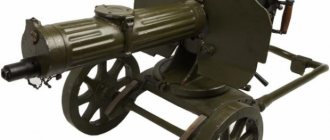
Replacing tank machine guns
Until 1962, tanks used a Goryunov machine gun. In this year, the gun was replaced by a more technologically advanced PKT that had improved tactical and technical characteristics. Accordingly, when replacing the design, the engineers made some changes, including sighting devices. They were removed because an optical sight was used to aim the gun at the target in the PKT.
Dimensions have also undergone changes. The barrel length, as well as the weight of the machine gun, was increased. The stock was removed from the design as unnecessary. In order to control the fire remotely, the gunsmiths added an electric start.
Temperature control device PKT-04S
The PKT alarm device is a temperature monitoring device, depending on the version, used for:
PKT 40S is designed to convert the resistance thermal converter signal into a unified direct current signal.
The device includes four IPS-1K converters.
The PKT 04C device is used for continuous single-position signaling of an increase or decrease in permissible temperature values.
The device includes four independent signaling devices STS-1K.
Data
In most cases, a Kalashnikov tank machine gun is paired with an anti-tank gun.
The PCB is installed on armored personnel carriers by attaching it to a special support. It, in turn, is connected to the armored vehicle using brackets. Thus, the barrel will be turned in the direction where it will be necessary to shoot.
Features of incomplete disassembly of a machine gun and its reassembly after incomplete disassembly
Incomplete disassembly procedure.
- Place the machine gun on the table (mat) with the muzzle forward.
- Check to see if there is a cartridge in the chamber.
- Remove the accessory and cleaning rod from the bag
- Separate the guide rod with the return spring
- Separate the bolt carrier from the bolt
- Separate the bolt from the bolt carrier
- Separate the firing pin from the bolt
- Separate the electric trigger (press the latch with a drift, move the electric trigger up until the guide protrusions come out of the vertical grooves of the receiver)
- Separate the trunk
- at points No. 2, 4, 5, 8, the machine gun is held by the electric trigger with the left hand
- It is not allowed to place the barrel on the ring ledge
Modernization
Like almost any weapon, the Kalashnikov machine gun has gone through a modernization process. This happened 8 years after the official adoption into service in the ranks of the Soviet army. That is, in 1969.
What has been modernized? The weight of the weapon was immediately reduced by 1.5 kilograms. From this time on, modernized models were able to use night sights that did not require illumination.
Monitoring devices Sh932.1PKT1
| / Products / Secondary devices / Devices for monitoring parameters of transformers Sh932.1PKT / Devices for monitoring Sh932.1PKT1 | print version |
Designed for operational monitoring of parameters with a liquid dielectric and control of the cooling system.
- are a means of measurement;
- two design options:
— for recessed panel mounting;
— for wall mounting;
- maintaining protocols of maximum and minimum parameter values for the controlled period;
- choice of cooling system;
- emergency alarm;
- unified current signals (4...20 mA) for controlled parameters;
- transferring information to the automated process control system via the RS-485 interface (ModbusRTU).
Modifications (versions):
- Sh932.1PKT1 - for operational monitoring of temperature parameters of transformers, control of the cooling system, signaling when the temperature exceeds the specified settings;
- Sh932.1PKT2 - determination of load factors, determination of the residual thermal life of insulation (in addition to the functions of PKT1);
- Sh932.1PKT3 - monitoring the oil level in the transformer and oil leakage (in addition to the functions of PTK2).
Table 1. Functions performed depending on the modification.
Source
The procedure for removing and installing a machine gun on a combat vehicle
Installation of a PKT machine gun.
- Give the gun barrel an elevation angle convenient for installation (15-40 )
- Install the machine gun in the car so that its barrel fits into the hole in the ball belt, and the holes in the lugs of the machine gun receiver coincide with the holes in slides 6 and 12.
- Insert the pins into the holes of the receiver and slides until they stop.
- Pull the lock 19 and attach the rod 4 to the machine gun reloading handle.
- Connect the machine gun's electric trigger connector, tighten the union nut and secure it with a cotter pin.
Dismantling the PKT machine gun.
- Give the gun barrel an elevation angle convenient for work (15-40).
- Turn off the battery switch and discharge the machine gun.
- Undo the cotter pin, unscrew the union nut and disconnect the machine gun's electric trigger connector.
- Remove checks 7 and 11.
- Pull the lock 19 and disconnect the rod 4 from the machine gun reloading handle.
- Remove the machine gun from inside the fighting compartment.
Penetration effect of steel core bullets
| № | Name of barrier (protective equipment) | Firing range in meters | Penetration depth in centimeters |
| 1 | Hard hat (steel helmet) | 1700 | — |
| 2 | Body armor | 1200 | — |
| 3 | Parapet made of dense compacted snow | 1000 | 70 — 80 |
| 4 | An earthen barrier made of loose sandy loam soil | 1000 | 25 – 30 |
| 5 | Dry pine beams 20x20 cm, fastened in stacks | 1200 | 20 |
| 6 | Brickwork | 200 | 10 — 12 |
The number of rounds required to hit a single target
| Range in m | Shooting in short bursts from a bipod while lying down or standing from a trench | |||||||
| head figure | chest figure | waist figure | running figure | running figure (profile) | machine gun | rocket anti-tank gun | anti-tank gun | |
| 100 | 3 | 3 | 3 | 3 | 3 | 3 | 3 | 3 |
| 200 | 5 | 4 | 3 | 3 | 3 | 3 | 3 | 3 |
| 300 | 7 | 6 | 4 | 4 | 4 | 4 | 4 | 3 |
| 400 | 12 | 8 | 5 | 4 | 5 | 6 | 4 | 3 |
| 500 | 19 | 11 | 7 | 5 | 7 | 8 | 4 | 3 |
| 600 | 26 | 15 | 8 | 7 | 9 | 10 | 5 | 4 |
| 700 | 20 | 10 | 8 | 12 | 14 | 7 | 4 | |
| 800 | 13 | 10 | 15 | 18 | 9 | 5 | ||
| 900 | 17 | 13 | 18 | 23 | 11 | 6 | ||
| 1000 | 16 | 23 | 30 | 13 | 7 | |||
| Range in m | Firing in bursts from a machine with fixed aiming mechanisms | |||||||
| head figure | chest figure | waist figure | running figure | running figure (profile) | machine gun | rocket anti-tank gun | anti-tank gun | |
| 100 | 3 | 3 | 3 | 3 | 3 | 3 | 3 | 3 |
| 200 | 3 | 3 | 3 | 3 | 3 | 3 | 3 | 3 |
| 300 | 5 | 4 | 3 | 3 | 3 | 3 | 3 | 3 |
| 400 | 8 | 5 | 4 | 3 | 4 | 4 | 3 | 3 |
| 500 | 12 | 7 | 4 | 4 | 5 | 5 | 4 | 3 |
| 600 | 16 | 10 | 5 | 4 | 6 | 7 | 4 | 3 |
| 700 | 21 | 13 | 6 | 5 | 7 | 9 | 5 | 3 |
| 800 | 17 | 8 | 6 | 8 | 11 | 6 | 4 | |
| 900 | 21 | 10 | 8 | 10 | 14 | 7 | 4 | |
| 1000 | 12 | 9 | 12 | 17 | 18 | 5 | ||
| 1100 | 15 | 11 | 15 | 21 | 10 | 5 | ||
| 1200 | 18 | 13 | 18 | 26 | 12 | 6 | ||