History of creation
It all started in 1861. It was during this time that Richard Gatling invented his “death machine.” We are talking about a 6-barreled machine gun with manual drive. The weapon turned out to be really lethal, but very inconvenient. In particular, the shooter had to turn the handle with one hand to fire, and with the other direct the turret towards the enemy. In addition, the Gatling gun was very bulky and heavy.
The problem required more modern solutions, and after some time an automatic machine gun appeared, in which recoil energy was used to reload the cartridge. However, this development seemed futile and expensive to the American military. In particular, such an arrangement required precise processing of parts, therefore, the involvement of qualified specialists.
Here it is necessary to clarify that the cost of manufacturing one automatic machine gun was almost equal to the production of one steam locomotive. Therefore, the decision of the military officials was quite fair, but as time has shown, it was wrong.
Maxim machine gun
Who invented
The inventor who introduced the military to a new type of weapon was named Hiram Stevens Maxim. Here it is necessary to clarify that Sir Hiram Maxim was not a hereditary gunsmith, and initially was not involved in the development of small arms at all. He was born in the small American town of Sangerville, where his father had a farm. Soon after the birth of their son, the parents decided to leave farming and moved to the city. Here the father of the future inventor opened a small turning workshop.
When Hiram completed his studies, he worked in his uncle's workshop, inventing various useful things along the way, such as powering steam boilers. When Maxim turned 26, he was on a business trip to Georgia, where he was invited to a shooting range. Stevenson proved himself to be a good shooter, however, after the recoil of the musket, his shoulder hurt badly. This nuance gave Hiram the idea that the weapon's recoil could be used for more practical purposes.
Returning home, he developed the principle of automatic reloading, where the recoil energy did not go outside, but sent the cartridge into the chamber. It was this project that was demonstrated to the American military.
When the project was rejected, Hiram forgot about his idea, and only remembered the machine gun after he was forced to emigrate to Great Britain. The machine gun's drawings were seriously modified, but again the weapon did not receive approval among the public. Maxim had to carry out serious marketing work, but still he managed to attract the attention of the famous banker Nathaniel Rothschild, who agreed to finance the dubious project.
Production stages
The patent for the Maxim heavy machine gun was issued in 1883, however, there were no buyers for this weapon for a long time. The machine gun was first used by British soldiers in 1893 to suppress an uprising in Africa.
The first buyer of the machine gun was the German Kaiser Wilhelm, who personally tested the weapon and purchased several copies. After this there was a demonstration in Russia, and Emperor Alexander III ordered 12 weapons. Like the German Chancellor, the Russian Tsar also personally tested the British machine gun.
After this, the massive distribution of “Maxims” began around the world. In particular, Russia alone has purchased almost 300 units of these weapons over 7 years.
Performance characteristics
Let us present the characteristics of the Maxim machine gun of the 1910 model, which was produced at the Tula Arms Plant.
- Structural weight: the machine gun itself/on the frame - 23.8/64.3 kg;
- Length - 1,107 mm;
- Number of rifling - 4 right-hand;
- Caliber - 7.62 mm;
- The design of the USM is striker type;
- The principle of operation is based on the recoil of the barrel, which is locked by a crank element;
- Rate of fire parameters - 600 rounds/min;
- The fuse is a lever type, located between the handles;
- Sighting device - rear sight and front sight, optional installation of optics;
- Firing range: targeted/effective - 2,700/800 m;
- Initial bullet acceleration - 740 m/s;
- Ammunition - metal belt for 250 rounds.
Shield
Shield
1 (Fig. 53) protects the gunner and his assistant from bullets and shrapnel. It is put on with lugs 3 on the washer and the head of the connecting bolt and secured by turning the bolt with its tail down. In the center the shield has a rectangular cutout 1b for aiming and a shaped cutout for the casing.
The lower part of the shield is bent forward at an angle of 40° to increase the vertical aiming angle. Cutouts 1b allow you to increase the horizontal aiming angle of the machine gun.
Rice. 53. Shield:
1 — shield (147A); 16 — cutouts; 1c - rectangular cutout for aiming; 2 — bolts (150); 3 — ears (148, 149)
The design of the Maxim machine gun
Let's look at how Hiram Maxim's machine gun works.
Main design elements
Generally speaking, Maxim’s heavy machine gun consisted of the following elements:
- Fuse;
- Sighting device;
- Locking mechanism;
- Filler and drain plug;
- casing;
- Steam removal system;
- Sleeve ejector;
- Trunk;
- Return spring;
- Trigger;
- Control handles.
Weapon drawings
Operating principle of a machine gun
The shooting mechanics are automatic. This principle is based on the recoil of the bolt and barrel of a machine gun under the influence of powder gases. When the elements move a certain distance, they disengage and continue to move independently of each other.
The weapon works as follows:
- The tape is fed into the receiver;
- The handle twitches, as a result the tape moves forward, and the cartridge ends up opposite the lock;
- The handle is distorted again, as a result of which the cartridge is captured by the lock and sent into the barrel;
- To shoot, you need to press the trigger, when the loaded cartridge flies out, the lock is pulled back under the influence of powder gases, the handle moves forward;
- The spent cartridge case, together with the new cartridge, goes down, the ammunition is sent into the barrel, and the cartridge case is ejected through a special tube.
Machine table
Table
(Fig. 43) serves to connect the machine gun body with the machine and to aim the machine gun. It consists of a board 1, a locking device 2, a clamping device 3, a swivel 4, a coarse vertical adjustment mechanism 5, a fine vertical adjustment mechanism 6 and a connecting bolt 7.
Rice. 43. Machine table:
1 — table board (4A); 2 - locking device; 3 - clamping device (sb. 4-4); 4 — swivel (1);
5 — rough vertical aiming mechanism (collection 5-5); 6 — fine vertical aiming mechanism (collection 5-1); 7 — connecting bolt (52)
Table board
(Fig. 44) is used to attach a swivel to it. It is a casting made of malleable cast iron, bent along the radius of curvature of the arcs of the machine frame. In the middle, the table board has a window 1 with a rim, in which the guide disk 1a of the swivel is placed (see Fig. 47). The edge of the window has a conical outer surface for tightly clasping it with a clamp. On the back of the table board there is a cutout 2 with a vertical hole 4 for the handle 8 and the stopper axis 4 (see Fig. 45).
Rice. 44. Table board:
1 - window with edge; 2 — cutout for placing the handle of the stopper axis; 3 - arc grooves; 4 — hole for the stopper axis
At the bottom, the table board has longitudinal arc grooves 3, with the help of which it is connected to arcs 2 (see Fig. 40) of the machine frame, and bosses with holes for placing the ends of stoppers 2 and 3 (see Fig. 45).
Locking device
(Fig. 45) serves to secure the table board to the arcs of the machine frame in the given position. The locking device consists of a box of stoppers 1, a large stopper 2, a small stopper 5, an axis 4, springs 6 of the large and small stoppers, cups 7 of the stopper springs, a handle 8 of the stopper axis, a washer 9 and a cotter pin 10.
Rice. 45. Locking device assembled and disassembled:
1 — box of stoppers (sb, 4-1); 2 — large stopper (83); 2a - spring socket; 2b - rack (comb); 3 — small stopper (84);
3b - rack (comb); 4 — stopper axis (88); 4a - gear; 5 — stopper axis washer (88A); 6 — stopper springs (86);
7 — cups of stopper springs (85); 8 — handle of the stopper axis (89); 9 — washer (91); 10 — cotter pin (92); 11 — handle button (90)
Box
1 of
the stoppers
is used to connect the stoppers to the axis 4. It has a hole at the top for the passage of the stopper axis, and at the bottom there is a hole with a bore for the washer 5 of the stopper axis. Inside, the stopper box has a rectangular channel in which stoppers with springs and spring cups are placed.
The stoppers enter with their ends into the holes in the arcs of the machine and thereby secure the table in its assigned position.
Large stopper
2 (left) is a rod with a diameter of 12 mm with a conical end, the thickened quadrangular part of which has a cylindrical seat 2a for a spring with a cup and a rack 2b with three teeth for engagement with the teeth of the gear 4a of the stopper axis.
Small stopper
3 is designed in the same way as the large stopper.
Axis
4
stoppers
with gear 4a are used to bring the stoppers together and spread them apart. A washer 5 is riveted to the bottom of the axis gear 4a. At the top, the stopper axis has a cylindrical end for putting on the washer 9 and a transverse hole for a cotter pin 10; on the sides there are six longitudinal projections for connecting to the stopper axis handle.
Springs
6
stoppers
serve to activate the stoppers. The stopper springs are cylindrical screw springs, they are made of round wire with a diameter of 1.5 mm.
Cups
7 are used to place stopper springs. There is a round hole in the bottom of each cup through which air escapes when the stoppers are closed (so that an air cushion is not created).
Pen
8 is used to rotate the stopper axis. It has a hole with six semicircular protrusions for putting stoppers on the axle and a rib at the bottom for strength. At the end of the handle there is a knurled button 11 for ease of use of the handle.
There may be machines that have a rib-shaped boss on the handle of the stop axis instead of a button.
Clamping fixture
(Fig. 46) serves to secure the swivel in the window of the table board. It consists of a clamp made up of two clamps 1 and 2, an axis 3 connecting the clamps to each other, and a clamping bolt 4 with a knob 5.
Rice. 46. Clamping fixture:
1 — right clamp (6B); 1у - eye with thread; 1l - corner groove; 2 — left clamp (7B); 2a - eye; 2p - corner groove;
3 — clamp axis (8); 4 — clamping bolt of the clamp (74); 4a - cylindrical part; 4р - thread; 5 — knob (10A); 6 - collar washer (11A)
Left clamp
2 is a semi-arc of a circle, at the ends of which there are ears. The front end eye is designed to connect the clamps to each other using the axis 3, and the rear end eye 2a has a smooth hole that is designed for the cylindrical part 4a of the clamp bolt.
An angular groove 2p (angle 106° 160′) is machined on the inside of the clamp to cover the edge of window 1 (see Fig. 44) of the table board and disk 1a (see Fig. 47) of the swivel. At the top of the corner groove there is a 1mm deep groove into which the lubricant is placed.
Right clamp
1 differs from the left one in the following: at the front end, the right clamp has an eye instead of an eye, and at the rear end there is an eye 1u, which has a threaded hole for screwing in the clamping bolt 4.
Axis
3
clamp
is a cylindrical rod with a diameter of 11 mm with a collar. Thanks to the collar, the upper end of the axle protrudes above the clamp and, when assembled, is placed in the swivel fork, which ensures joint rotation of the clamp with the swivel.
Clamp bolt
4 tightens the clamps on the swivel disk. It has a knob 5 with washers 6 for easy screwing of the bolt into eye 1 of the right clamp.
Swivel
1 (Fig. 47) serves for horizontal aiming of the machine gun and horizontal dispersion when firing. It consists of disk 1a and two frames 1c.
In the front part of the disk there is a fork into which the collar of the axle 3 (see Fig. 46) of the clamp fits. At the bottom of the disk there is an annular protrusion that fits into the annular groove in the inner wall of window 1 of the table board (see Fig. 44) and prevents lateral movements of the swivel relative to the table.
The swivel frames 1c have holes 1b on top, through which the annular protrusions 2c of the rods pass (see Fig. 49) and the connecting bolt 6 (see Fig. 52). The rear ends of the frames are thickened and have holes 1d, in which the bolt 4 (see Fig. 49) of the rough vertical guidance mechanism is placed. On the left frame, near the bolt hole, there is a threaded hole for screwing in a locking screw.
Rice. 47. Swivel:
1 — swivel (1); 1d — swivel disk; 1b - holes for the annular protrusions of the rods; 1s bed; 1d - holes for bolt
Ammunition supply diagram
To start firing a machine gun, the safety is raised and the upper trigger plate is pressed. This action pulls the rod back and rotates the lower release, which in turn releases the ankle lock. Considering that the ankle no longer holds the trigger, it moves forward under the action of the return spring and breaks the primer. Powder gases push the barrel and frame back and exit through the holes in the muzzle. A new cartridge is automatically removed from the belt, and the spent cartridge case is thrown away.
On a note! Here it is necessary to clarify that, unlike most weapon systems, the return spring of the Maxim system machine gun does not work in compression, but in tension.
Shooting is carried out in automatic mode as long as the shooter presses the trigger. The barrel is cooled by liquid, water is poured through the pipe and fills the barrel casing. However, the machine gun has a very high rate of fire, so after about 600 shots, the water stops performing a cooling function and begins to boil.
To solve this problem, it was recommended to mix water with glycerin in a certain proportion or use glycerin-based liquids, for example, “Steol”. In winter, alcohol diluted in water was used to cool the trunk.
Maxim machine gun: device
Machine frame
Machine frame
(Fig. 36) connects all parts of the machine. It consists of a trunk 1 with a coulter, two arches 2, a connection bolt 3, a spacer 4, a combat axle 6 and wheels 5.
Rice. 36. Frame of the flock (top view):
1 - trunk (sb. 2); 2 — arcs (63, 63A); 3 — connection bolt (74D); 4 — spacer (68A); 5 — wheels (sb. 3); 6 — combat axis (collection 1-1);
6a - annular beads; 7 — nut of the combat axle (66); 8 — split nut (sb. 140)
Trunk with opener
(Fig. 37) serves as a support for the machine gun when firing and for the convenience of transporting the machine gun manually. The trunk is bent under the arches when carrying the machine over long distances, as well as when transporting a machine gun on a cart or in a pack.
Rice. 37. Trunk (top view):
1 — trunk pipe (93); 2 — hinge (94A); a - hole in the semicircular protrusion; 3 - opener (98A);
3c - cylindrical protrusion of the opener; 5 — earring (166A); 5a — hole for the strap; 5c - earring loop
Right and left hinges 2 are put on the ends of the trunk pipe to connect it with the arches, which are welded and additionally secured with a through rivet.
Each hinge has a semicircular protrusion with a hole 2a, through which the trunk axes pass, connecting the trunk and the spacer with the arches.
Rice. 38. Vomer and earring (longitudinal section of the trunk):
1 — trunk pipe (93); 3 - opener (98A); For - vomer spike; Sound cylindrical protrusion;
4 — opener rivet (96B); 5 — earring (166A); 5a - hole for attaching the strap; 6c — earring loop
The hinges have ledges on top that they... rest against the ledges of the arc, which limits the upward rotation of the trunk.
At the rear end of the trunk, an opener 3 with a spike 3 is attached by electric welding and rivets 4 (Fig. 38), which prevents the machine from sliding backwards during shooting.
At the front, the opener has a cylindrical protrusion Zv with trunnions at the ends, onto which the loops 5v of the earrings are put.
Earring
5 is the coulter skid when rolling the machine on wheels. The earring is made in the form of a runner made of sheet steel. At the bent end it has a hole 5a for attaching a strap. When firing, the earring is folded forward, and when the machine gun is rolling, the earring is installed under the opener to facilitate sliding of the trunk along the ground. In machines manufactured before 1941 (Fig. 39), the earring 3 is connected to the opener 2 using an eye 5. The eye consists of two ears connected to each other by a pin 6. The ears have holes at the ends. With the front holes, the eye is put on the ends of the bolt 8 of the earring, and with the rear holes - on the ends of the trunnion 2a of the opener. One loop 4 is riveted to the earring, covering bolt 8 of the earring in the middle part.
Rice. 39. Trunk of a machine made before 1941
1 — trunk tube (93); 2 - opener (98A); 2 - opener (98A); 2a opener journal; 3 — earring (166A);
4 - loop (167); 5 — eye (100); 6 — eye pin (101A); 8 — earring bolt (169)
Arcs
(Fig. 40) serve to impart elevation angles when aiming a machine gun at a target by moving the table forward or backward. The right and left arches are arranged in the same way. The arches on top have smooth curved rails along which the table slides with its grooves.
The front ends of the arcs each have one hole 2a with a bore on one side for putting on the combat axis and key grooves 26 for placing the keys of the combat axis 6. Threaded holes 2zh are intended for fastening screws 9 nuts 7 of the combat axis. On the sides of the arcs there are six conical holes into which the ends of the stoppers fit when securing the table to the arcs in the position given to it. The rear ends of the arcs end with eyes 2g with transverse round holes for attaching the trunk and spacer using the axles 5 of the trunk (see Fig. 41).
Rice. 40. Arcs with a combat axis:
2 - arcs (63, 63A); 2a - holes for the combat axis; 26 — keyway; 2c - rail; 2g - eyes for connecting to the trunk;
2d - holes for the connection bolt; 2e - ledges; 2g - hole for the fastening screw of the combat axle nut; 6 — combat axis (collection 1-1);
6a — ring collars 7 — combat axle nuts (66); 8 — split nuts (sb. 140); 9 — fastening screws (63B); 10 — cotter pins
In front of the eyes there are 2D holes for the passage of the threaded ends of the connection bolt.
The ledges 2e serve to limit the upward rotation of the trunk.
Rice. 41. Connection bolt and spacer:
3 — connection bolt (74D); 5a - annular beads; 4 — spacer (68A); 5 — trunk axes (69A);
trunk axle cotter pins (142); 7 — connection bolt nuts (74B); 8 — nut washers (74B); 9 — nut cotter pins (74E)
Link bolt
3
with spacer
4 (Fig. 41) serves to connect the rear ends of the arcs and maintain their parallelism. The connection bolt has threads at the ends for screwing in nuts 7 and holes for cotter pins 9. Ring collars behind the connection bolt maintain a constant width of the rear ends of the machine arcs.
There may be machines in which the annular collars of the connection bolt are made separately from the bolt and are in the form of rings placed on the bolt and welded by electric welding.
Spacer
4 at the ends has threaded sockets for screwing in the axes 5 of the trunk, secured with cotter pins 6.
Combat move
(see Fig. 36) is the front support of the machine gun and is used to transport the machine gun manually during short dashes. It consists of two wheels 5, a combat axle 6, two axle nuts 7 with two fastening screws and two split nuts 8 with two cotter pins.
Rice. 42. Combat wheels:
1 — wheel tire (172A); 2 — wheel rim (170A); 3 — rim clips (173); 4 — rim holder rivet (174);
5 — knitting needle (71A); 6 — connecting washer (137B) of two types; 7 — outer washer (136); 8 — washer bolt (assembly 3-1);
9 — washer bolt nut (144); 10 — cotter pin, nut, washer bolt (145); 11 — wheel hub (138A); 12 — coil spring (146)
Combat wheels
(Fig. 42) are constructed identically and can be placed at either end of the combat axis. The wheel consists of the following parts: tire 1, rim 2, consisting of four jambs, four cages 3, four rivets 4 cages, eight spokes 5, connecting washer 6, outer washer 7, three bolts 8 with nuts 9 and cotter pins 10, bushings I , three bushing locking screws and a coil spring 12.
Tire
1 wheel is held together by a rim. It is a welded steel hoop with four holes for rivets 4.
Rim
2 wheels composed of four jambs made of oak or ash,
There may be machines in which the wheel rim consists of eight jambs, eight cages and eight clip rivets.
The jambs at the ends have sockets for tenons and in the radial direction there are two holes for attaching spokes 5. Clips 3 secure the rim at the joints of the jambs. The holder is made of a steel plate and has a hole for a rivet. The 4-ring rivet holds the cage, rim and tire together into one.
Spokes
5 are made of oak or ash; some ends of the spokes are inserted into the holes of the rim, and the other ends converge in the center of the wheel, forming the wheel hub together with the washers and bushing.
Outer washer
7 is hollow and has three holes on the flange for bolts 8.
Connecting washer
6 inside has a two-stage cylindrical boring with a thread at the beginning of each stage. Split nut 8 is screwed into the larger diameter bore (see Figures 36 and 40), and wheel hub 11 is screwed into the smaller diameter bore.
On the flange of the washer there are three holes for bolts 8 that secure the washer in the center of the wheel.
In Fig. 42 shows washers 6 of two types (in the assembled wheel there is a washer of a simplified design). The connecting and outer washers are fastened with bolts 8 and secured on the side of the connecting washer with nuts 9 and cotter pins 10.
Sleeve
The 11th wheel has a through channel for the combat axle. To reduce wear on the combat axle, the wheel hub is made of bronze. The inside of the bushing has a groove for lubrication.
A helical spring 12 is placed between the end of the combat axle and the bottom of the connecting washer. It serves to reduce the run-up of the wheel, which increases the stability of the machine gun when firing.
Combat axis
6 (see Fig. 36 and 40) connects the front ends of the arches. Wheels are put on the ends of the axle. The combat axis is a cylindrical rod on which there are ring flanges 6a, which determine the width of the front ends of the arcs.
There may be machines in which the annular shoulders of the combat axle are made separately from the axle in the form of rings, put on the combat axle and welded to it.
On the combat axis, next to the shoulders, keys are tightly seated, which fit into the keyways of the arcs and keep the combat axis from rotating relative to the arcs.
Next to the keys on the combat axis there is a thread for screwing on nuts 7.
Nuts
7 are used for fastening the arches on the combat axle and for connecting the wheel with the combat axle using split nuts 8. Nut 7 has a hexagonal head for the key, a collar with six cutouts for the head of the fastening screw and a collar for connection with a split nut. The nut channel has a smooth and threaded part. The threaded part of the nut is screwed onto the combat axle.
Split nut
8 is bronze and consists of two halves. One half has two round sockets, and the other has two pressed-in tenons for connecting the halves together. The split nut has a threaded part on the outside for connection with connecting washer 6 (see Fig. 42), a recess for a cotter pin and a hex collar for a key. The split nut is put on the smooth part of the nut 7 of the combat axle and, after screwing it into the connecting washer, its end rests against the shoulder of the nut 7 of the combat axle, which is how the wheel is secured to the combat axle.
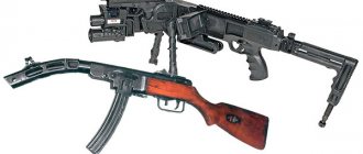
Known modifications
It should be noted right away that despite the complexity of the design, the Maxim machine gun was a very effective weapon, therefore, in some countries, gunsmiths developed similar types of weapons, improving the basic design.
The most successful modifications include:
- MT. This is a version of the Maxim-Tokarev light machine gun. This model was developed by the famous Soviet gunsmith Fedor Tokarev, and the machine gun was produced by the Tula Arms Plant in 1924.
- M/32-33. This is a Finnish development, brought to life by designer Aimo Lahti. Unlike the prototype, the rate of fire of this modification was 800 rounds/min. Machine guns of this series were actively used during the Finnish military campaign against the Red Army.
- Vickers. A heavy machine gun adopted by the British Army in 1912, and removed only in the early 60s. In addition to the British, such machine guns were produced in Australia, America and Portugal. It should be noted that starting in 1916, Vickers machine guns were installed on aircraft.
- MG 08. One of the main machine guns of the Wehrmacht at the beginning of World War II. Note that by the time of the attack on the Soviet Union, this modification was considered technically obsolete, however, it continued to be used due to the lack of similar weapons.
- MG 11. This model was created by Swiss gunsmiths and was converted to fire a standard cartridge, 7.5 mm caliber.
- PV-1. Version developed for use by military aircraft. There was no liquid cooling shroud and the mounting system was redesigned.
- Type 24. Chinese version of the Maxim machine gun. Production of the modification began in 1935, with a total of about 36,000 units produced. A continuation of this series can be considered the Type 36 machine gun, where the liquid cooling system was replaced by an air one.
All of the above modifications were intended for firing rifle cartridges. However, in the history of the Maxim machine gun, there were also large-caliber versions, for example, the Vickers 50, with a caliber of 12.5 mm. Twin versions were also developed, which were used as anti-aircraft guns.
Maxim PV-1 machine gun
Machine gun "Maxim" model 1910
The Maxim machine gun of the 1910 model was a modernized version of the machine gun of the 1905 model. Its serial production was carried out at the Imperial Tula Arms Factory (ITOZ) from May 1905 under license (England). The main role in finalizing the systems of both Maxim models and putting machine guns into production belonged to Guard Colonel Tretyakov and senior class master Pastukhov, who served at ITOZ. The essence of the modernization, which was carried out in 1909, was to create a lighter machine gun. Some parts made of bronze (barrel casing, receiver, handles, etc.) were replaced with steel ones. The sight, parts of the casing and box, the trigger rod, and the butt plate were also changed. The first two machine guns modernized by Tula gunsmiths were submitted for testing on June 15, 1909 (where they became competitors of the new Vickers machine gun). After appropriate modifications, the Tula “light” machine gun was adopted for service, giving it the designation “Maxim heavy machine gun of the 1910 model” with a field wheeled machine gun of Colonel Sokolov. Serial production of the new modification of the Maxim and the machine began in 1911. The machine gun of the 1910 model was indeed significantly improved compared to the prototype, primarily in technological terms, but it is hardly correct to say that “Russian technicians created, in fact, a new machine gun,” which is established in Russian literature.
The machine gun consisted of: barrel; a frame that included a locking mechanism, a drum, a handle and a chain; bolt (lock) with impact mechanism, combat cylinder, lifting and locking levers; trigger pull; box (riveted) with a hinged lid; butt plate with safety catch, trigger lever and control handles; return spring with casing (box); a receiver having a tape feeding mechanism; barrel casing with sleeve and steam outlet tube, drain and fill holes; sighting devices; muzzle
The automatic system implemented a barrel recoil scheme with a short stroke. The barrel bore was locked by a system consisting of two articulated levers. The connecting rod (front lever) was connected to the bolt with a flat hinge, and the crank (rear lever) was also hinged at the rear of the frame, that is, the frame was the receiver. At the right end of the bloodworm axis there was a swinging handle, at the left there was an eccentric (drum) with a Gall chain, which was connected to the return spring. The return spring was mounted in a separate box located on the left wall of the Maxima box. The lock was equipped with a drummer with a double-leaf mainspring. The combat cylinder, which had grips to hold the cartridge case, slid vertically in the grooves of the lock and had a hole for the firing pin to pass through, so the shot could only be fired if the cylinder was in a certain position. The drummer cocked his ankle. At the same time, the upper safety release captured him. The ankle, with its combat platoon, stood on the lower descent.
The trigger lever, which had a finger button, was placed between the control handles and was held in place by a safety lock. A canvas cartridge strip was inserted into the transverse window of the receiver on the right. The tape nests were separated by metal plates fastened with rivets. In this case, the rivets were placed with a slight interference fit, which made it possible to firmly hold the cartridge in the socket. The cartridge box was installed separately from the machine gun. For reliable operation of the feed, the second number supported the tape with his hands in the correct position. The weight of the canvas tape was 1.1 kg. The cutout wall of the left frame of the receiver frame activated the feed mechanism. On the first Maxim machine guns of the 1910 model, a reel was installed on the box, designed to direct the canvas tape to the receiver. Later the coil was moved to the shield.
1 - fuse, 2 - sight, 3 - lock, 4 - filler plug, 5 - casing, 6 - steam exhaust device, 7 - front sight, 8 - muzzle, 9 - cartridge outlet tube, 10 - barrel, 11 - water, 12 - pourer plug, 13 - cap, steam outlet, 15 - return spring, 16 - release lever, 17 - handle, 18 - receiver.
The shot was fired from a closed bolt. It was necessary to lift the safety and press the trigger lever. At the same time, the trigger rod moved back, pulling the tail of the lower trigger, which released the ankle. The firing pin passed through the hole in the cylinder, breaking the cartridge primer. The lock, under the influence of recoil, tried to move back, transferring pressure to the crank and connecting rod. The crank and connecting rod formed an angle, the apex of which was facing upward, and rested against the protrusions of the frame with their hinge. The barrel and frame with the lock moved backwards. After the movable system had traveled about 20 millimeters, the handle ran onto the fixed roller of the box and rose, turning the crank down. As a result, the lever system straightened and the lock was pressed more closely to the bore. After the bullet had ejected, the powder gases entered the muzzle, pressing on the front section of the barrel, and the moving system received an additional impulse. The design of the Russian-style muzzle was developed by Zhukov and finalized by Pastukhov. The barrel, moving back, opened transverse holes in the muzzle, through which excess powder gases were discharged. By turning, the handle caused the levers to fold down and move away from the lock barrel. In this case, the handle acted as an accelerator of the lock, transferring to it the kinetic energy of recoil and braking the frame and barrel. The lock cylinder, holding the spent cartridge case by the rim, removed it from the chamber. When lowering the connecting rod, the tube of the locking levers pressed on the tail of the ankle, which, turning, cocked the striker. The lifting levers lifted the larva, capturing the next cartridge from the receiver window (the window was longitudinal). During the further movement of the system backwards, curved leaf springs located on the inside of the box lid lowered the cylinder. Simultaneously with this cranked lever, the slider of the feed mechanism was moved to the right. The slider's fingers jumped for the next cartridge. When the handle was turned, the chain wound around the drum, stretching the return spring. The weight of the barrel was 2.105 kilograms, the moving system - 4.368 kilograms. The rear stroke length of the barrel was 26 millimeters, the lock relative to the barrel was up to 95 millimeters. Coordination of the movement of the lock and the barrel was achieved by adjusting the tension of the return spring.
Operation of the automatic system of the Maxim machine gun
At the end of the rotation, the handle hit the roller with its short shoulder and began a reverse rotation (early samples of the Maxim machine gun had a separate spring for this). The moving system moved forward under the action of the return spring. The lock sent the cartridge into the chamber, and the spent cartridge was sent into the cartridge outlet tube, from where it was pushed out during the next cycle. The crank lever shifted the slide to the left, and it advanced the next cartridge to the receiver window. When turning the crank and connecting rod, the tail of the safety release was raised by the tube of the locking levers. When the combat larva stood opposite the striker with its hole, the upper trigger released the firing pin and, if the trigger lever was pressed, a shot was fired.
The machine gun consisted of 368 parts. The maximum gas pressure in the barrel was about 2850 kg/sq.cm, and the average was about 1276 kg/sq.cm. During training, a blank firing bushing was used, which was screwed into the muzzle. When the mainspring broke, the debris was removed through the bottom of the box.
The Maxim machine gun of the 1910 model had a rack-mounted sight mounted on the lid of the box. On the rack there was an aiming bar, which had divisions for aiming at range. On the transverse tube of the clamp, divisions were marked along which the rear sight was installed. The front sight of a triangular cross-section was inserted into a groove on the casing. The length of the aiming line was 911 millimeters. The height of the front sight above the axis of the bore was 102.5 millimeters, so the accuracy of the casing had a great influence on accuracy. The sight was set to a range of up to 3.2 thousand steps (2270 meters), but the effective range did not exceed 1.5 thousand meters.
The capacity of the casing was about 4.5 liters. Some machine guns had casings with longitudinal fins, which increased rigidity and increased the cooling surface, but fins were abandoned in favor of simplifying production. Canvas or rubber hoses used in some armies to vent steam into the atmosphere or into a condenser canister were used in the Russian army only in armored installations.
Armored trains were heavily armed with machine guns. Russian armored train of the Hunhuz type in Galicia, 1916. Both Maxim and captured Schwarzlose machine guns were used to arm such armored trains.
With the help of a crank mechanism, smooth and almost shockless operation of the automation was ensured. The use of a power supply system drive from the frame was rational from the point of view of uniform distribution of recoil energy. The Maxim system had high survivability and reliability, which ensured its exceptional longevity. Despite the fact that the external position of the handle was dangerous for the crew, it facilitated the assessment of the condition, as well as the determination and elimination of delays in firing. The production of a machine gun was quite complex and required not only high-quality steel and skilled workers, but also numerous special equipment. Some equipment was also required for assembly and initial running-in of the units.
Sokolov's machine, which he developed with the participation of Platonov, a master of the St. Petersburg gun factory, consisted of a frame with a trunk, wheels and a table. The rim and spokes of the wheels were made of oak, the tire was made of steel, and the nuts and bushings were made of bronze. The table carried a clamp-type swivel with a clamp, fine and coarse vertical aiming mechanisms, as well as a shield. The machine gun was attached to the swivel by the front eyes of the box. The lower eye connected the machine gun and the head of the lifting mechanism. Rough vertical alignment was carried out by moving the table along the arcs of the frame. In the first version of the machine, the frame had two foldable legs, a seat, and a roller at the end of the trunk. This design made it possible to fire from two positions and roll the machine gun by the strap. When carried, the legs folded back and the trunk forward. Later, the front legs, roller and seat were eliminated, and a small opener was strengthened at the end of the trunk. These changes led to the fact that the maximum elevation angle decreased to 18 degrees (from 27), and the declination to 19 degrees (from 56); shooting was carried out only from a prone position. The mass of a 6.5-mm shield measuring 505x400 millimeters was 8.0 kilograms (with a reel guiding the tape - 8.8 kilograms). It was believed that the shield would protect the machine gun crew from rifle bullets at a distance of over 50 meters. Although the convenience of a wheeled machine even on slightly rough terrain is questionable, in our country the addiction to them lasted a long time.
Installation of Maxim machine guns in the turrets of the Austin armored car built at the Putilov plant
Before the complete “victory” of Sokolov’s machines in Russia, several installations were used with the Maxim machine gun. The field and fortress wheeled carriages were removed from service before 1914, but the Vickers tripods of the 1904, 1909 and 1910 models remained.
The Vickers tripod of the 1904 model had a mass of 21 kilograms, the height of the firing line was 710 millimeters, the vertical guidance angle was from -20 to +15 degrees, the horizontal guidance was 45 degrees, its modification of the 1909 model, which had a new lifting mechanism, had a mass of 32 kilograms , vertical guidance angle - from 15 to +16 degrees, horizontal guidance - 52 degrees. The 1910 model tripod had a mass of 39 kilograms, the mass of the shield 534x400 millimeters was 7.4 kilograms, the vertical aiming angle was from -25 to +20 degrees, horizontal - 52 degrees, and occupied three fixed positions at the position.
In 1915, the Kolesnikov system, which was easier to manufacture and lighter, was added to the Maxim machine gun. This machine was produced by the Petrograd gun factory, Kyiv, Bryansk and Petrograd arsenals. The Izhevsk and Sormovo factories were engaged in the production of shields. Kolesnikov’s machine had a tubular boom with a coulter and rope loops instead of handles, 305 mm oak wheels with steel tires and hubs and bronze bushings, horizontal and vertical guidance mechanisms, and a shield mount. The disadvantage of the design was that the axis of the barrel bore was too high relative to the axes of the wheel travel and the vertical guidance mechanism. This increased dispersion during shooting. The mass of the machine was 30.7 kilograms, a 7-millimeter shield measuring 498×388 millimeters was 8.2 kilograms, the vertical guidance angle was from -25 to +32 degrees, and the horizontal guidance was 80 degrees. The machine consisted of 166 parts, including knitting needles. During the war, the machine gun and machine gun were painted in a protective color.
To save money during the training of machine gunners, instead of live cartridges, manufactured cartridges with a reduced powder charge were used. A box of live ammunition intended for machine guns was marked with the letter “P” before being sent to the troops.
A large number of proposals were received from foreign companies and domestic inventors regarding sights, as well as devices for conducting “hidden” firing from machine guns. The latter consisted of a periscope sight mounted on the parapet of the trench and an additional trigger lever. Such sights were tested, but not a single sample was accepted for service.
The pressing problem of firing at air targets has given rise to many different options for improvised anti-aircraft installations among the troops. For Sokolov’s machine, for example, they developed a stand with a clip for anti-aircraft shooting. In the fall of 1915, master Kolesnikov made a tripod “machine gun mount for firing at aircraft.” The machine, developed in the workshops of the Rifle Range, provided large elevation angles and all-round fire, aiming was free, a clamp was used to fire “at the point,” and a butt could be attached. Titular adviser Fedorov presented an anti-aircraft gun, easily made from scrap materials. The machine gun was mounted on it with a Sokolov machine gun. This installation made it possible to fire at vertical guidance angles from +30 to +90 degrees. The 5th Department of Artcom decided to send descriptions of these installations to the troops, transferring them from “procurement” to their own discretion. The standard anti-aircraft machine gun mount was never transferred to the Russian Army.
Lieutenant General Kabakov, inspector of the rifle unit in the army, on October 11, 1913, in a note to the Aeronautical Unit of the GUGSH, gave recommendations for converting the Maxim machine guns into aviation ones - although these recommendations were not implemented, however, five years later, similar changes were made by the Germans to the MG machine gun. 08/18.
© RIA Novosti, Infographics
The procedure for unloading the Maxim machine gun, model 1910: Press your fingers at the bottom of the receiver tray on the right side to remove the tape. Pull it back twice and then release the cocking handle located on the right side of the box. Using a pencil or other object suitable for this purpose, make sure that there is no cartridge or cartridge case in the under-barrel front tube. Raise the safety and press the release lever.
The procedure for partial disassembly of a 1910 model Maxim heavy machine gun with a Sokolov machine gun: 1. Before disassembling, pour the coolant out of the casing. Separate the shield from the machine. To do this: loosen the nut of the connecting bolt; the tail of the bolt head is turned upward to a horizontal position; the shield is removed upwards. 2. Open the box lid by pushing the clasp forward with your thumbs. 3. The lock is removed. To do this: send the handle forward with your right hand until it stops; With your left hand you take the frame of the lock and lift it up a little; smoothly lowering the handle, the lock rises from the box; the lock turns and is removed from the connecting rod. 4. The firing pin is lowered to release the mainspring. To do this, it is necessary: holding the combat cylinder in the uppermost position, press the tube of the locking levers to the platform; release the hammer from the upper descent; by pressing on the tail of the lower trigger, smoothly release the firing pin. 5. The receiver is taken with both hands and pulled out upward. 6. The box with the return spring is separated. To do this, the box is moved forward so that the hooks come off the box spikes, after which the drum chain is removed from the return spring hook. 7. The butt plate extends. To do this, you need to squeeze the head of the split pin with your fingers, pulling it to the side; push the butt plate up by holding its handles with both hands (if it is difficult to extend the butt plate, you can use a special lever device). 8. Fold the handle forward, grasping the roller and the bolt, pull the right bolt to the right, grasping the left bolt from both sides from behind and pull it out. 9. The frame with the barrel is removed. To do this: the connecting rod will rise and rest on the crank; grab the handle with your right hand, fixing it (do not let it turn), grab the drum with your left hand, push the frame back; clasp the barrel and the extended end of the left frame with your left hand; remove the frame with the barrel from the box. 10. The barrel is separated from the frame. To do this: with your left hand grasping the end of the left frame and the barrel, with your right hand the right frame is moved to the side and removed from the barrel axle; after this the left frame is removed. 11. The trigger rod is removed. To do this, the rod is applied to itself, lifted upward by the end and removed from the box. 12. By turning to the right, the cap is removed from the muzzle; the bushing is unscrewed from the muzzle using two keys; The muzzle is unscrewed with a drill key.
The procedure for assembling a machine gun: 1. The rod is inserted into the box. Its hole is put on a spike in the bottom of the box, while the rod spike is inserted into the hole in the bottom of the box; the thrust moves forward all the way. 2. The barrel and frame are connected: take the barrel with the rear oil seal wound on it in your left hand (the number should be turned upward) and put the frame frame on the barrel axles - the left one, and then the right one. 3. Insert the barrel and frame: place the connecting rod on the crank; carefully slide the barrel into the casing and the frame into the box. 4. Lift the handle to insert the right latch; push in the left one. 5. Insert the butt plate. To do this, hold the buttplate by the handles and slide it onto the box slats using the grooves. In this case, it is necessary that the thrust be in the forward extreme position. Insert a pin on the right side. 6. Attach a box with a return spring. To do this, it is necessary to position the tension screw knob vertically; put the handle in place and put the drum chain on the hook of the spring (the spring is circled from below); holding the machine gun, move the box forward and place the box hooks on the box spikes. 7. Insert the receiver. To do this, the receiver is inserted with grooves into the upper cutouts of the box; The slider should be in the left position. 8. Screw in the muzzle. Wind the front seal onto the muzzle end of the barrel, screw the bushing into the muzzle, insert the muzzle into the hole in the casing, and then screw the muzzle. 9. Place a lock in the box. To do this, the connecting rod is raised, and the firing pin is cocked. After this, holding the lock with its horns forward and the combat cylinder upward, put the tube of the lock levers onto the connecting rod until it stops, turn the lock and place it in the box; While holding the lock, send the handle forward and release it. The lock should fit into the grooves of the frame ribs with its pad. 10. Close the box lid. 11. Raise the safety, press the release lever. 12. Place the cap on the muzzle.
Technical characteristics of the Maxim heavy machine gun, model 1905. Cartridge – 7.62 mm model 1891 (7.62×53); The weight of the machine gun “body” (without coolant) is 28.25 kg; The length of the machine gun “body” is 1086 mm; Barrel length – 720 mm; Initial bullet speed – 617 m/s; Sighting range – 2000 steps (1422 m); Rate of fire – 500-600 rounds/min; Combat rate of fire – 250-300 per minute; Belt capacity – 250 rounds.
Technical characteristics of the Maxim heavy machine gun, model 1910: Cartridge – 62 mm model 1908 (7.62×53); The weight of the machine gun “body” (without coolant) is 18.43 kg; The length of the machine gun “body” is 1067 mm; Barrel length – 720 mm; Initial bullet speed – 665 m/s; Rifling – 4 right-hand; Rifling stroke length – 240 mm; Initial bullet speed – 865 m/s; Sighting range – 3200 steps (2270 m); The longest firing range is 3900 m; The maximum flight range of a bullet is 5000 m; Direct shot range – 390 m; Rate of fire – 600 rounds/min; Combat rate of fire – 250-300 rounds/min; Belt capacity – 250 rounds; Weight of the loaded belt – 7.29 kg; Tape length – 6060 mm.
Technical characteristics of the Sokolov machine: Weight with shield – 43.5 kg; Vertical guidance angle – from -19 to +18 degrees; Horizontal guidance angle – 70 degrees; The height of the firing line is about 500 mm; The greatest length of the machine gun with the machine is 1350 mm; Stroke width – 505 mm; The distance from the center of gravity to the coulter is 745 mm.
Based on materials: S. Fedoseev - Machine guns in the First World War
Advantages and disadvantages
Let's start with the positive characteristics of the Maxim heavy machine gun. These include the following indicators:
- High rate of fire;
- Good accuracy;
- Reliability of the design;
- Possibility of firing in long bursts;
- Impressive ammunition;
- Armor shield protecting the shooter.
The weapon also had disadvantages. For example:
- Low mobility;
- Large structural mass;
- Not the best range of effective fire;
- Bulky dimensions, complicating camouflage;
- A large number of components, which complicated production;
- Water dependence;
- Machine gun crew of 2 people.
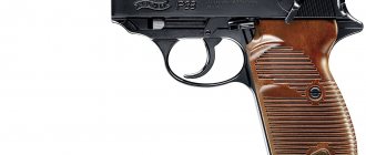
"Maxims" for Switzerland. MG11 machine gun
Which countries was it used in?
The machine gun was in service with the following armies:
- Bulgaria;
- Great Britain;
- Germany;
- Greece;
- Italy;
- Serbia;
- Turkey;
- Russia;
- Ukraine;
- Romania;
- United States of America;
- Montenegro;
- Finland;
- Switzerland.
It should be noted here that the list contains countries that themselves produced the Maxim machine gun or purchased weapons in large quantities. Single copies of these weapons have appeared almost all over the world.
Maxim MG 08 machine gun
Representation in culture and art
You can see a Maxim system machine gun in many films dedicated to the Civil and Great Patriotic Wars. This weapon can hardly be called a mass or main one, but Maxims were used very widely on the battlefields.
Among the most famous films and TV series where this machine gun appears are:
- "State border";
- "Chapaev";
- “Bread, gold, revolver”;
- "Chapaev";
- "Soldiers" - 1956;
- "Dnieper Frontier";
- "Sixth".
The Vickers machine gun, built on the Maxim base, can be seen in the pictures:
- "Bridge on the River Kwai";
- "On Guard of Death";
- "Hero's return".
The name of this weapon is also found in songs. For example:
- Maxim machine gun - Agatha Christie;
- Two Maxims - author of poems by V. Dykhovichny.
In documentary chronicles of the war years, Maxim machine guns are found very often, including foreign modifications.