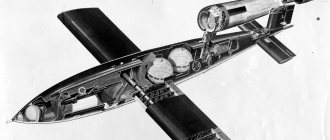
In addition to the charge, the warhead contains a control unit. It is also small in size - about the size of a can - and performs several tasks at once. The main thing is detonation of the charge at a certain, strictly calculated height. Nuclear weapons are not intended for use on the earth's surface - except perhaps to disable the underground launch silos of enemy ballistic missiles, writes Popular Mechanics. The optimal altitude for triggering missile warheads is considered to be 1200 meters. In this case, the blast wave reflected from the ground merges with another, diverging to the sides, and strengthens it - this is how the main damaging factor of a nuclear explosion, an all-crushing shock wave, is formed.
The automatics of the warhead controls the steering motors: pneumatic or powder, and monitors the thermostatic stabilization of the charge, since the weapons-grade plutonium from which it is composed tends to heat up in a calm state. In addition, the cone has an on-board electrical network with power supplies and electromagnetic pulse protection. All this equipment is securely mounted on shock absorbers and enclosed in a durable power frame, covered on top with a thick layer of thermal insulation.
I'll get off at the farthest station
The technology by which warheads are separated from the missile and set on their own courses is a separate big topic about which books can be written. Therefore, let’s just say that today the “bus” scheme is used: the breeding unit slows down at the right place, turns around, releases the warhead - in order not to lead it astray, it can even turn off its engines for a while - then it accelerates again and follows to the next stop. This whole ballet takes place at an altitude of 1200 kilometers, where artificial Earth satellites fly.
Having separated from the last stage, the warhead reaches the top of its trajectory and then begins to fall towards the Earth. It enters the atmosphere at an incredible speed - 15 times faster than sound - its outer shell heats up to five to six thousand degrees and begins to burn. The worst part is the nose part - in warheads it is made of quartz and covered with the thickest layer of thermal insulation. However, the sides are not easy either: the air turned into plasma polishes the burning surface of the warhead, like sand or sandpaper, taking away the heat-protective coating.
At an altitude of 50 kilometers above the surface, the warhead enters the dense layers of the atmosphere and experiences powerful negative overloads: the air slows it down no worse than a concrete wall slows down a speeding car. This is where the power frame works together with the shock-absorbing mounts - otherwise the contents of the warhead will be torn from their regular places, breaking the power and communication cables.
Connected by one goal
The thermonuclear charge and the control unit continuously communicate with each other. This “dialogue” begins immediately after installing a warhead on a missile, and it ends at the moment of a nuclear explosion. All this time, the control system prepares the charge for operation, like a trainer prepares a boxer for an important fight. And at the right moment he gives the last and most important command.
When a missile is placed on combat duty, its charge is equipped to its full configuration: a pulsed neutron activator, detonators and other equipment are installed. But he is not ready for the explosion yet. Keeping a nuclear missile in a silo or on a mobile launcher for decades, ready to explode at any moment, is simply dangerous.
Therefore, during flight, the control system puts the charge in a state of readiness for explosion. This happens gradually, using complex sequential algorithms based on two main conditions: reliability of movement towards the goal and control over the process. If one of these factors deviates from the calculated values, the preparation will be stopped. The electronics transfer the charge to an increasingly higher degree of readiness in order to give a command to operate at the calculated point.
A nuclear explosion occurs instantly: a warhead flying at the speed of a bullet manages to travel only hundredths of a millimeter before the entire power of the thermonuclear charge turns into light, fire, impact and radiation - and all this is of terrifying force.
The invisible complexities of rocketry: Part 4. More about engines and tanks
The tribute that rocket technology developers have to pay to the imperfections of our world is varied and unpleasant. Today we'll talk about the cost of upgrading liquid jet engines and the subtle challenges facing tank designers.
Schemes of liquid rocket engine operation
The existence of different schemes allows developers to choose the right one, with the desired advantages (ease of use, ease of production, high thrust or high specific impulse) and acceptable disadvantages.
Displacement feed
The simplest option. The boost gas pressure (at first there was nitrogen, now they have switched to helium en masse) provides the necessary pressure parameters at the inlet to the engine. The first rocket experiments of GIRD and Goddard were carried out using displacement feed, but it did not disappear from the scene over time. This circuit is used in propulsion systems of satellites and spacecraft. "Soyuz", "Shuttle", "Apollo" used it. The displacement feed combines especially well with the UDMH/AT fuel pair due to its self-ignition. The result is a simple, reliable engine with the ability to be turned on multiple times. Advantages:
- Simplicity.
- Reliability.
- Cheapness.
- There is no mass loss on the turbopump unit.
- High efficiency for low thrust engines
Flaws:
- Low specific impulse.
- Not suitable for high thrust engines.
Open circuit
To increase thrust, specific impulse and engine power, a pump was already needed. Only a turbine could provide the required parameters. The first “real” rockets - V-2, R-7 - used a separate working substance - concentrated hydrogen peroxide - to drive the turbine, but then they switched to burning a small proportion of fuel components. The gas generator exhaust was first simply thrown to the side, creating a very impressive torch:
Atlas launch vehicle launches.
Pay attention to the size, power and color of the torch. It is clearly seen that the TNA operates on excess fuel, which burns out in the atmospheric air. Draining generator gas directly overboard looked wasteful, so they began to direct it to the supercritical part of the nozzle - and a little UI will add, and how
will work:
Classic picture - F-1 engine
However, the drainage of an open-circuit gas generator has another interesting use case - as a roll control engine:
Second stage of the Falcon-9 launch vehicle. Turning the exhaust pipe generates a twisting force that controls the roll of the stage. View in dynamics (from the third minute)
The open scheme is still in use today, and is unlikely to disappear in the near future. Due to the relatively small loss of UI, it makes it possible to make a more powerful engine (F-1) or a cheaper engine (RS-68), or to make development possible for a team with limited resources (Merlin).
Advantages:
- Simpler and cheaper than a closed circuit.
Flaws:
- Lower specific impulse than closed circuit.
Closed circuit
A logical solution to increase engine performance was an attempt to direct the gas generator exhaust into the combustion chamber so that it would burn under the best conditions for generating thrust.
This task turned out to be quite difficult - there is a very high pressure in the combustion chamber, additional questions arise about the stability of the engine, because another feedback “TNA-combustion chamber” is added. The USSR was the first to make closed-circuit engines - the NK-15 and NK-33 were installed on the N-1 heavy rocket, the RD-253 works on the Proton. The United States took up this scheme quite late - the first closed-loop rocket engine of the United States was the shuttle propulsion engine SSME, which, on the other hand, became the first closed-cycle engine using oxygen/hydrogen steam. Marvel at the complexity of the engine
Advantages:
- Highest UI.
Flaws:
- The most complex and expensive scheme.
Phase change circuit
An elegant "hack" of rocket engine physics - the need to cool the engine nozzle is used as a source of energy to operate the turbopump unit.
The design was invented for the RL-10 engine, which has been used in the Centaurus upper stage for fifty years. Advantages:
- There is no mass loss on TNA.
- Simplicity of design.
- Reliability.
Flaws:
- Suitable only for oxygen-hydrogen pairs.
- The pressure is lower than in the scheme with TNA, therefore, the UI is lower.
Tank interiors
There is also a lot of interesting stuff inside the launch vehicle tanks. The tanks are located one above the other, so we need supply pipelines for the “upper” component, pressurization pipelines, and also, perhaps, it is necessary to solve the problem of fuel components with different temperatures being located nearby. And there is also the problem of fuel fluctuations, which also needs to be solved.
Component Piping
This is the fuel tank (lower) of the first stage of the Soyuz-2.1v launch vehicle. Note the large pipe with a corrugated casing. This is the oxidizer pipeline. Since the oxidizing agent is liquid oxygen, it is necessary to install thermal insulation so that the kerosene does not freeze on the pipe. Alas, all this requires additional mass.
And this is the Angara launch vehicle. Highlighted in yellow is a pipeline that performs the same function. Judging by the proportions, this is also an oxidizer pipeline (oxygen tanks are larger than kerosene tanks for the oxygen-kerosene pair), but located on the side to simplify and reduce the cost of production. On the one hand, this is unaesthetic, but the digital control system will cope with the asymmetry of the rocket.
Intertank compartment
On the second and third stages of the Saturn V rocket, a very beautiful solution was used - the oxygen and hydrogen tanks had a common wall: On the left is the first stage with an intertank compartment, on the right is the second stage with a common wall.
Red is fuel, blue is oxidizer. The difficulty was that liquid hydrogen and oxygen had a temperature difference of 70 degrees Celsius. Therefore, the wall consisted of two layers of aluminum with thermal insulation between them. This design saved as much as 3.6 tons in the second stage. Interestingly, the fuel tank of the Space Shuttle was in some sense a step back; it had a classic intertank compartment.
Pressurization pipelines
If you expanded the SSME diagram above, you would see the outputs of gasified hydrogen and oxygen there. They were used to pressurize the corresponding tanks. On the one hand, we saved weight on separate boost gas tanks, on the other hand, we got an additional pipeline:
Damping partitions
If you carefully looked at the pictures of the sections of the tanks, you saw rings of various widths and crosses at the bottom of the shuttle tanks. These are special elements for damping fuel vibrations. The crosspieces at the bottom of the shuttle's fuel tank serve to prevent the formation of a crater when the tank is emptied. The fact is that the funnel can lead to the gaseous component of the fuel being sucked in, which can cause problems in pipelines and engines. Ring-shaped elements serve to dampen fuel vibrations. Since it is liquid, fuel overflowing to one wall during a maneuver can cause problems for the stabilization system. The partitions can be very large, as in the first stage of the Saturn I: Or practically absent, as in the third stage of the Saturn V: The video is long, but I recommend watching it - it’s very interesting to see the behavior of liquid hydrogen during rocket acceleration and in zero gravity .
The general rule is that the more maneuvers are expected from the stage, the larger the size of the partitions is installed. For example, the Soviet block “E” is the third stage of the Vostok launch vehicle. Here the partitions are almost the entire height of the tank, because the unit can maneuver very actively, but the fuel cannot be allowed to splash:
And all this, alas, is an additional cost of mass.
Tank emptying and synchronization system
Another problem that has to be solved. First, the combustion of each engine is somewhat unique. There will definitely be slight variations in thrust and consumption of fuel components. Even for one engine, a special system must be installed so that the fuel and oxidizer run out at the same time. And if we have several tanks or side stages, then we have to install a special system that will ensure the simultaneous completion of components in several stages. Now this system is also called a fuel consumption control system and consists of a set of level sensors and a digital computer, which, in addition to controlling the rocket, also solves this problem:
The third stage of the Soyuz launch vehicle.
Along the axis of the tanks there are level sensors for SURT. However, even despite the efforts of the SURT, it itself has an accuracy limitation, so some small fraction of the fuel is still lost. It is taken into account when refueling, adding to the so-called. "guaranteed fuel supply."
Epilogue
I recommend watching the series “Moon Machines” (Russian version, English version).
The difficulties that have to be solved when designing space technology are shown very well and clearly. For navigation:
- First article in the series.
- The second article is solid fuel engines.
- The third article is types of liquid fuel, geometric dimensions, transportation.

