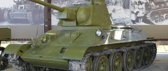
T-34-76 model 1942, Medium tank
Since the T-34 tank was produced at different enterprises, there were differences between the manufactured models and samples. In August 1939, the Main Military Council adopted the T-34 as the main medium battle tank of the Red Army. The new project was completed during December 1939 and became known as the T-34 tank of the 1940 model. On December 19, 1939, drawings and models of the new T-34 were presented to the High Command, which recommended the new tank for production, despite the fact that a prototype had not yet been manufactured.
Diesel engines. The first production samples of T-34 tanks were equipped with V-2 diesel engines, but due to their shortage, the old M-17 gasoline engine began to be installed on the tanks. The T-34 tank experienced such problems with the transmission that the tanks often went into battle with spare transmission parts bolted to the power compartment cover with steel cables. The T-34 of the 1940 model had a turret made of rolled armor plate and a short-barreled 76.2 mm L-11 gun of the 1938 model. The gun was installed in a cast cradle, which was welded to the casing. The T-34 model of 1940 became the standard model for all variants of the tank. They had interchangeable elements, including the engine, weapons, transmission and periscopes. The designers' main concern was simplicity of design. The tank had a welded hull made of rolled steel sheets. The designers used a Christie suspension with five large twin steel rollers on each side and a large gap between the second and third pairs. The drive wheel, located on the stern side for safety reasons, was a gear drum used on BT series tanks. It drove cast manganese steel tracks with central guide pins located on alternating tracks. The first T-34 models had a turret with a noticeable protrusion and a massive hatch that occupied the entire rear of the turret. The T-34 tank of the 1940 model was equipped with one periscope located in the front left. At the end of 1941, a small number of tanks were produced equipped with a long-barreled 57 mm ZIS-4 cannon, designed to engage lightly armored targets at greater distances than the 76.2 mm L-11 cannon.
T-34 model 1941. The second model of the T-34 appeared in 1941. Essentially, it was a command tank of the 1940 model with a turret made of rolled armor plate, equipped with a more powerful 76.2 mm L/41.5 gun of the 1940 model. The same bulky hatch remained on the turret, but some versions of the tank had two observation devices. The hull design remained the same, but a box for property was now installed on the right fender. The most notable feature of the T-34 tanks of the 1941 model was the replacement of the cast cradle with a corner one, which was secured with bolts. In 1942, tanks with a cast turret and new, wider tracks appeared. Some tanks were equipped with flamethrowers (ATO-41) and armored gas tanks mounted on the stern.
T-34 model 1942. In 1942, a cast turret (as opposed to a rolled sheet turret) became standard. The new turret weighed 4.4 tons with a ring diameter of 1.38 m. The tank had various improvements made taking into account the experience of combat use. The tank commander and gunner now each had a separate hatch. In addition, a new hull-mounted 7.62 mm DT machine gun was installed, which was more effective in close combat. At the beginning of 1942, designers developed a new model of the T-34 - T-34M. It had a chassis similar to that of the KV heavy tank (but with smaller diameter rollers), and a completely new hull and turret shape. However, this tank was not accepted for production. The only element of its design that was used for the next model, the T-34/76 model of 1943, was the hexagonal turret. As mentioned above, the T-34 tank of 1943 was designed taking into account information from the battlefield, which stated that one of the shortcomings of the T-34 was the turret protrusion overhanging the rear of the hull. This made the tank vulnerable to German anti-tank infantry who would climb onto the tank and place flat mines under the turret ledge. A new cast hexagonal turret without a projection appeared on the T-34 of the 1943 model. The new model had other innovations, including increased fuel capacity and weldable armor plate components.
Tank T-34/76E. Subsequent models of the T-34/76 are better known in the West by their British classification. Models E and G were produced in 1943. The hull and turret of the T-34/76 remained the same, but the tank received new, more efficient air purification and lubrication systems. The hull design was improved by using an automated welding technique for higher quality materials, which produced higher quality joints. Model E clearly demonstrated the success of Soviet industry. It became clear that each new T-34 model would be stronger and better armed.
Tank T-34/76F. Model F had a different appearance from other T-34 models, in particular the commander's panorama. The main differences were, however, inside the tank the T-34/76F received an improved and more efficient chassis. The old four-speed gearbox has been replaced with a five-speed one. It became easier to change gears, the speed of the tank increased. Improved air filters were used. The mechanical part of the T-34/76F was significantly different from the earlier T-34 models. However, a small number of tanks of this model were produced, as the situation began to change dramatically. In 1943, it became obvious that the 76.2 mm gun installed on the T-34 tank did not meet the requirements of the time. The model received many improvements, including more powerful armor, but the weapons remained insufficient. The appearance of German tanks equipped with long-barreled 75-mm and 88-mm cannons with high muzzle velocity finally confirmed that the T-34 should receive more powerful weapons. The result was the appearance of the T-34/85 tank.
Tank T-34/85-1. Developed in 1943, the T-34/85 was a rearmed T-34 tank with an 85 mm cannon. The tank had a new turret, originally developed for the KV-85 tank with a ring diameter of 1.56 m. The enlarged turret provided space for one more crew member, and the tank commander was able to concentrate on performing his immediate duties, without being distracted by gunfire. . The first T-34/85-1 were sent to the elite guards tank units. The new guns quickly proved their usefulness. They were developed on the basis of the pre-war 85-mm M1939 anti-aircraft gun, had an effective firing range of 1000 m and, it was claimed, could penetrate the frontal armor of Tiger and Panther tanks.
Chassis and suspension. The T-34 tank chassis, based on the Christie system, had five pairs of large rollers with a gap between the second and third pairs. The suspension of each roller was independent and suspended perpendicularly on a coil spring inside the housing. The drive sprocket was mounted at the rear, which reduced vulnerability. The same system was used on BT series machines. The drive sprockets rotated wide cast manganese steel tracks with central guide pins located on alternating tracks. Wide tracks gave a small specific pressure on the ground, not exceeding 0.7-0.75 kg/cm2. For British, German and American tanks, the value of this parameter was 0.95-1.0 kg/cm2. The fenders covered the upper part of the suspension system and protruded 25 cm in the front of the hull and 10 cm in the rear. The suspension allowed the T-34 tank to maintain high speed even when moving over very rough terrain, while the wide tracks of the tank weighing 28.3 tons made it possible to move through mud and deep snow.
Hull and armor. The hull, designed by Nikolai Kucherenko, hung over the tracks and had sloping sides. It was welded from rolled sheets of homogeneous steel. The thickness of the hull armor at the front was 45 mm, 40 mm at the rear and 20 mm at the top. The quality of the welding was very poor, but not so bad as to allow the welds to fail. The front armor plate, 45 mm thick, mounted at an angle of 60 degrees, had no openings, with the exception of the driver's hatch and the embrasure of the ball machine gun mount. There was a periscope in the driver's hatch. The sloped armor provided excellent protection from projectiles and was equivalent in protective properties to a 75 mm thick vertical armor plate. In fact, the T-34 tank was the most invulnerable in 1941. The roof of the rear part of the hull behind the turret was slightly raised, and the engine compartment louvers and exhaust pipes were placed on it. The upper rear plate and engine cover were secured with screws. If it was necessary to replace the engine or transmission, they could be removed.
Engine. The engine was located in the rear of the hull and was a V-shaped four-stroke 12-cylinder liquid-cooled diesel engine, originally developed for the BT-7M tank. This version of the 3.8 liter engine was upgraded for the T-34. At 1800 rpm it developed power of 493 hp. The power/weight ratio was 18.8 hp. per ton, which allowed the T-34 tank to reach a speed of 54 km/h on the highway and 25 km/h over rough terrain, depending on its nature, with an average fuel consumption of 1.84 l/km. When driving on the highway, this parameter improved significantly. The V-2 engine also made it possible to significantly increase the cruising range of the T-34 (up to 464 km) compared to tanks that had conventional gasoline internal combustion engines. The main fuel tank was located inside the hull, four cylindrical auxiliary tanks were on the sides and two smaller tanks were at the stern. The transmission was located in the rear of the hull and did not clutter up the fighting compartment and control compartment. At the beginning of the war, the transmission was unreliable, so some crews carried spare transmissions, tying them to the engine compartment with cables.
Tower. All models of the T-34 tank had a low turret. Although the low silhouette of the turret was useful in combat, it limited the deflection of the main and secondary armament barrels, especially on a reverse slope or when firing at short range. In addition, it was cramped inside the tower. From the control room one could immediately get into the tower. On later models, handrails for landing began to be welded to the turret and hull.
Driver and controls. The control area was separated from the engine compartment by a partition. The driver's workplace was located on the left side of the hull. It was equipped with a large hatch mounted on hinges. The hatch had a periscope for observation. The driver controlled the tank using a system with an onboard clutch and brake. The system was controlled by two control levers and a gear shift lever, as well as clutch pedals and a foot brake. The levers were connected to the transmission in the stern using metal rods running along the bottom of the gunk. To control the T-34 tank, it was necessary to exert more physical effort than to control Western-made vehicles, on which the transmission and gearbox were located next to each other. Driver mechanics of T-34 tanks often had to use a wooden hammer if the levers jammed. The four-speed gearbox on the last 100 T-34 tanks of the 1943 model was replaced by a five-speed one. As a result, it became easier to change gears and increase the speed of the tank. The floor contained the fuel injection, clutch and brake pedals. There was a pedal in the bottom (often called a “landing pedal”) that made it possible to stop the tank. There were also two compressed air cylinders for starting the engine at low temperatures.
Gunner-radio operator. The radio operator's workplace was located on the right in front of the hull. The hatch for leaving the vehicle was located in the bottom directly in front of the radio operator. The gunner-radio operator's armament consisted of a 7.62-mm Degtyarev tank machine gun in a ball mount with a horizontal aiming angle of 24 degrees and vertical aiming from -6 to +12 degrees. Machine guns mounted on tanks of the 1942 model were equipped with an armored mask. Despite the fact that at the beginning of the war there were no radio stations on most T-34 tanks and, due to an acute shortage of personnel, the radio operator’s position was empty, the number of tanks equipped with radios was constantly growing. In 1941, the vehicles of tank company commanders were equipped with the 71-TK-Z radio station. Efforts were made to equip platoon commanders' tanks with radios. During the first two years of the war, 71-TK-1 radios were also used. The situation improved when, at the end of 1942, the mass use of 9-P radio stations began. Although the range of these radios was 24 km, when moving they were effective at a distance of 8 km.
The Germans, who paid increased attention to providing crews with stable radio communications, noted the low quality of tactical interaction between Soviet vehicles. Due to the lack of radio communications, the Russians had to rely on flag signals. There was even a special hole in the tower hatch for giving signals using flags. In practice, this was very inconvenient - the platoon commander was too busy controlling his own tank and shooting. Often he simply gave the command to other crews to follow him. The situation improved as radio production increased, and by the summer of 1943, 75-80 percent of all vehicles were equipped with them. Internal communication between crew members was carried out using the TUP system. Tank helmets were equipped with headphones and throat microphones.
Tank commander and loader. The main drawback of all T-34 tanks was the poor ergonomics of the turret. There were three people in the turrets of the German vehicles: a gunner, a loader, and a tank commander, who was responsible for observing the terrain, managing the crew, and coordinating actions with the rest of the unit’s tanks. A completely different situation took place in the cramped, two-person turrets of the T-34. The commander had the same tasks as the German, in addition, he had to fire the cannon. This in itself is a serious matter, which distracted the commander from fulfilling his command duties. Loading also took a long time. Despite this, the Soviet command conducted a short and unsuccessful experiment, placing the responsibility for loading the gun instead of firing on the tank commander. The crew members who were on duty in the turret sat on seats hanging from the turret shoulder strap. The commander sat to the left of the gun, and the loader, who was also supposed to fire from the machine gun coaxial with the gun, to the right.
The quality of the optical equipment of the T-34 tank was inferior to the quality of the equipment of German tanks. The main 2.5x telescopic sight TOD-6, which was installed on the first T-34 models, was later replaced by the TMFD sight. Tanks that went into battle straight from the assembly line of the Stalingrad Tractor Plant in the fall of 1942 often did not have sights at all. They could only fire directly. Aiming was carried out by the loader directly through the barrel. To observe the surrounding area, the commander and loader used a PT-6 periscope. Later, periscopes PT-4-7 and PT-5 began to be used. Due to war-related shortages, periscopes were often not installed for loaders. The periscope's field of view was very narrow, and it could not be increased by holes in the armor made at the level of the commander's and loader's shoulders. Under the observation holes there were embrasures for firing a pistol, another embrasure. On later T-34 models these embrasures were absent.
Many German crew commanders preferred to fight with their heads out of the hatch. This provided them with a 360 degree view. If the T-34 commander tried to do this, the large forward-opening hatch would almost completely block his view. He would have to sit directly on the turret, not only risking coming under enemy fire, but also being hit by a very heavy hatch. The size of the hatch was such that, when opened, it also revealed the loader. T-34 tanks of the 1943 model had separate hatches for the commander and loader, but only the latest models were equipped with surveillance devices that provided a 360-degree view. The tower itself was originally made of rolled sheets with a cannon in a cast cradle. On the 1941 model, the cast cradle was replaced with a bolted corner cradle. In 1942, a cast turret with an armor thickness of 52 mm was adopted for service, although it was no different from a turret made of rolled sheets.
Main weapons. The first T-34 tanks of the 1940 model were armed with a short 76.2 mm L-11 gun of the 1938 model with a barrel length of 30.5 calibers. In 1941, a very small number of T-34s were armed with the 57mm long-barreled high-power ZIS-4 cannon, designed to engage lightly armored targets at long ranges. The greater power of the gun compensated for the reduction in caliber. But the L-11 remained the standard gun for the T-34 model of 1940.
However, the engineers had a more successful gun, although there were bureaucratic difficulties in installing it. The OKB of Plant No. 92, headed by designer V. Grabin, developed a new 76.2 mm F-32 cannon. It was installed on new heavy KV tanks. When firing at armored targets, due to the longer barrel, the gun showed much better results compared to the L-11, which was equipped with the T-34 tanks of the 1940 model. By the end of 1940, an employee of the V. Grabin Design Bureau, P. Muravyov, adapted the F-32 cannon for installation on the T-34 and on its basis developed a new cannon (F-34 with a barrel length of 42 calibers), significantly superior to the L-11. On their own initiative, V. Grabin and the director of plant No. 92, A. Elyan, began production of the F-34 along with the L-11 and sent both guns to the Kharkov plant, which was engaged in the production of T-34 tanks.
Tanks of this model (T-34 model 1941) were mainly used as tanks for platoon and company commanders and after the start of the German invasion they performed very well in battles, thanks to their increased firepower. Stalin became aware of this from reports of war correspondents from the front line. Units fighting on the front line required more tanks equipped with the effective F-34 gun than the L-11, so in the summer of 1941 the State Defense Committee finally approved the F-34 gun as standard for the T-34 tank. The F-34 had a conventional semi-automatic breech. The commander could fire either manually or using a pedal; he was responsible for the horizontal rotation of the tower manually or using an electric drive. When fired from the F-34, these shells penetrated the armor of the German PzKpfw III and IV (the thickness of the frontal armor was 50 mm) from almost any distance.
The F-34 gave the T-34 such an advantage in range and destructive power that the Germans had great difficulty resisting the T-34 tank. The PzKpfw IV with frontal armor 80 mm thick was put into service only in the spring of 1943. The Red Army continued to remain in a leading position - the BR-350P armor-piercing projectile was adopted. It penetrated 92 mm armor when fired from a distance of 500 m - approximately the same distance as firing in a tank battle. However, the appearance at the front in 1943 of new German tanks, specially designed to fight the T-34, radically changed the situation. When firing from a normal distance, the F-34 could not penetrate the frontal armor of the Tigers and Panthers. During the Battle of Kursk in July 1943, T-34 tanks were forced to approach German tanks at direct fire range or maneuver in such a way as to reach their flank or rear. The problem was solved when the 85-mm gun was adopted at the end of 1943. Initially, the T-34's ammunition capacity was 77 rounds. On the T-34 model 1943 it was increased to 100 rounds. The standard ammunition consisted of 19 BR-350AAP rounds, 53 F-354 or OF-350XE rounds and 5 SH-350 rounds.
Additional weapons. The first 115 T-34 tanks of the 1940 model were armed with a DT machine gun in the rear of the turret for rearward firing. The 1928 model machine gun had an effective firing range of 800 m and a rate of fire of 600 rounds per minute. To avoid jamming and overheating, the rate of fire was reduced to 125 rounds per minute. The machine gun had a retractable metal butt, a wooden pistol grip and a separate optical sight instead of the diopter sight mounted on the infantry machine gun. The disk-type magazine contained 60 cartridges, placed in two rows. In total, the ammunition load contained 35 disks, one half of which was stored in racks on the rear wall of the turret, and the other in the front part of the hull next to the gunner-radio operator.
New hexagonal tower. Deputy People's Commissar of Defense and Head of the Main Artillery Directorate G.I. Kulik did not like the T-34 tank, so he insisted on making various changes. As a result, production of T-34 tanks was interrupted in the early stages, and the Council of People's Commissars ordered the development of a program to improve the T-34. The improved vehicle received the designation T-34M. The project was terminated. Morozov developed a new turret for the T-34M, taking into account the shortcomings identified during the combat use of early model vehicles. For example, German infantrymen from anti-tank teams climbed onto a combat vehicle from the rear and installed an anti-tank disc mine under the turret ledge. In addition, the ledge formed a trap, from which incoming shells bounced directly into the vulnerable turret ring. The new cast hexagonal turret developed by Morozov was first installed on the T-34 tank of the 1943 model. It was devoid of many shortcomings: it had no protrusion, was much simpler to manufacture and larger than the towers of earlier models. Consequently, there was slightly more space in the turret for the crew. However, the problem of a small and overworked crew was finally solved only with the appearance of the three-seat turret of the T-34/85 tank, production of which began in the winter of 1943.
Tactical and technical characteristics of the T-34 mod. 1942
Length, m – 5.92 Length with gun, m – 6.62 Width, m – 3.0 Combat weight, t – 26.8 Armament: Gun – 1 x 76 mm F-34 Machine guns – 2 x 7.62 -mm DT Mobility: Max speed on the highway, km/h – 54 Cruising range on the highway, km – 300 Reservation: Front of the hull, mm – 45 Sides and rear of the hull, mm – 40-45 Front of the turret, mm – 40-45 Sides and rear of the tower, mm – 45 (52) Roof, mm – 15-20
IN THE YEAR OF THE ROOT FRACTURE
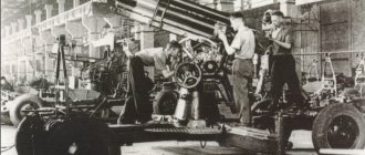
In the second half of 1942, new enterprises joined the production of the T-34. The reason was obvious: the German offensive in the south and the possible loss of STZ, the second most important manufacturer of T-34 tanks. The first to “lender a shoulder” to the Stalingrad tractor plant was the famous “Uralmash” - the Ural Heavy Engineering Plant (UZTM).T-34 tank with an “improved” turret from the 106th Tank Brigade. September 1942
Uralmashzavod was connected to armored hull production for the T-34 and KB in accordance with the GKO decree of October 31, 1941. However, until March 1942, he only produced cuttings of hulls, which he supplied to Krasnoye Sormovo and Nizhny Tagil. In April 1942, complete assembly of hulls and production of turrets of the T-34 tank for plant No. 183 began here. And on July 28, 1942, UZTM was instructed to organize the production of the entire T-34 tank and double the production of turrets for it due to the shutdown of plant No. 264. Serial production T-34 began production at Uralmash in September 1942. When mastering the serial production of the tank, many problems arose, for example, with the turrets - due to the increase in the program, the foundries could not ensure the implementation of the plan. By decision of the plant director B. G. Muzurukov, the free capacity of the 10,000-ton Shleman press was used (on the same press - there were two of them in the USSR - turrets for the T-34M were stamped in Mariupol on the eve of the war). Designer I.F. Varkhrushev and technologist V.S. Ananyev developed the design of a stamped turret made of 45 mm armor plate, and from October 1942 to March 1944, 2,050 units were produced. At the same time, the plant not only fully provided for its program, but also supplied a significant number of such towers to ChKZ. It should be noted that the shell resistance of the stamped turret was higher than that of the cast one, despite the smaller wall thickness. UZTM did not produce tanks for long - until August 1943. Then this enterprise became the main one for the production of self-propelled guns based on the T-34.
Tanks accepted by the crews on railway platforms in the delivery shop of plant No. 183. Nizhny Tagil, winter 1943
In July 1942, the State Defense Committee gave the order to the Chelyabinsk Kirov Plant to begin production of the T-34. At ChKZ, tank assembly was organized on the basis of tractor production, while maintaining full production of heavy KV tanks. On August 22, the first “thirty-fours” left the ChKZ workshops. In March 1944, their production at this enterprise was stopped in order to increase the production of IS-2 heavy tanks.
In 1942, plant No. 174 in Omsk also joined the production of the T-34. The design and technological documentation was handed over to him by plant No. 183 and UZTM.
The constant quantitative increase in the production of tanks and the attraction of more and more factories to it ultimately led to a sharp decline in the quality of tanks, and this process began already at the end of 1941. Thus, already from January 1942, complaints about the low quality of the T-34 tank, especially those produced by STZ and plant No. 112, began to be increasingly received from the active army. The situation was especially depressing at STZ, where the quantitative growth in tank production was especially rapid. The head of the GABTU, Lieutenant General Y. Fedorenko, wrote on April 27, 1942 to V. Molotov, who oversaw the tank industry in the State Defense Committee:
“Of the 290 tanks presented in March, 55 vehicles were rejected (15 due to low oil pressure, 22 due to a ruptured gearbox housing, 2 due to engine seizure).
After removing the white camouflage in 31 T-34 vehicles in the 90, 6, 107, 48th tank brigades, cracks were discovered in the armor of the hull and turret, I ask for your urgent measures to eliminate defects and improve the quality of manufacturing and assembly of T-34 hulls at STZ and plant No. 264."
As a result, the quality scandal reached the highest level. Having delved into the essence of the issue and learned, for example, about the non-interchangeability (either complete or partial) of even such large units as tank turrets, J.V. Stalin fell into a rage.
On June 5, 1942, GABTU military commissar N.I. Biryukov wrote in his work diary:
“Instructions from Comrade Stalin:
1. Improve the existing T-34 tank for one and a half to two months.
2. The main defect of our tanks is that they cannot make long transitions.
3. The weak point in tanks is the unreliability of transmission mechanisms.
4. The tank should be simple, rough, durable, designed for the average tanker.
5. Focus on improving tanks."
On June 30, 1942, the GABTU of the Red Army raised the issue of the quality of the T-34 with the government and presented “basic requirements for improving the tank:
a) verify drawings and technical specifications;
b) remove from production substitutes that have not been tested;
c) strengthen quality control departments at factories;
d) replace the stringless mount on STZ-produced tanks in the army (
final drives.
– Approx.
auto) for strings; e) introduce oil radiators on all tanks.”
However, these demands did not have the desired effect, partly because the front was very close to Stalingrad, and it was pointless to demand from the plant, which was working under bombing, to improve the quality of the tanks produced. It's good that he released them at all.
The quality of Sormovo tanks also left much to be desired. In this regard, it would be appropriate to quote the words of Stalin, who in June 1942 wrote to V. Malyshev: “... and in conclusion, Comrade Malyshev, I really want to hope that you will finally be able to do something about the “Sormovo monster” who is feared Our tankers will fight..."
From September 11 to 13, 1942, a conference of NKTP factories dedicated to the quality of the T-34 was held at UTZ in Nizhny Tagil. It was led by Deputy People's Commissar of the Tank Industry Zh. Ya. Kotin. In the speeches of him and the chief inspector of the NKTP G. O. Gutman, harsh criticism was voiced against the factory teams. Moreover, many of the listed shortcomings strangely coincided with those indicated in the report of the NIBTPolygon after testing three production T-34 tanks in the fall of 1940.
A T-34 tank with a stamped turret produced by UZTM leaves the assembly shop of the Chelyabinsk Kirov Plant. August 1943
The criticism had an effect: during the second half of 1942 - the first half of 1943, many changes and improvements were introduced to the T-34. In the fall of 1942, they began to install aft external fuel tanks of rectangular or onboard cylindrical (on ChKZ tanks) shape. Since the end of November, the drive wheel with rollers was returned to the tank, and stamped road wheels with rubber tires were introduced. Cyclone air cleaners began to be installed in January, and a five-speed gearbox began to be installed from March-June 1943. In addition, the ammunition load was increased to 100 artillery rounds, a turret exhaust fan was introduced, in 1943 the PT-4-7 periscope sight was replaced by the PTK-5 commander's panorama, and many other smaller improvements were introduced, such as landing rails on the turret. Serial production of T-34 tanks of the 1942 model (as they are unofficially, but most often referred to in the literature) was carried out at factories No. 183 in Nizhny Tagil, No. 174 in Omsk, UZTM in Sverdlovsk and ChKZ in Chelyabinsk. Until July 1943, 11,461 tanks of this modification were produced.
265 Comparative sizes of T-34 and M3s tanks
In the summer of 1943, they began installing a commander's cupola on the T-34. An interesting detail: three and Krasnoe Sormovo defend their priority in this matter in factory reports on tank building for the period of the Great Patriotic War. In fact, the Tagil residents proposed installing a turret at the rear of the turret behind the hatches and placing a third tanker in the turret, as on the experimental T-43 tank. But even two crew members were cramped in the “nut”, what a third! Although the Uralmash turret was located above the left commander's turret hatch, it was of a stamped design, and it was also rejected. And only the cast Sormovo “registered” on the “thirty-four”.
In this form, the T-34 tank was in serial production until the middle of 1944, and it was produced by plant No. 174 in Omsk the longest.
At the end of 1942 - beginning of 1943, the organizational structure of the armored and mechanized forces of the Red Army continued to improve.
Loading ammunition into a tank. Voronezh Front, 1943
In September 1942, the formation of mechanized corps began. The need to create such formations was caused by a number of reasons, the basis of which was factors of an operational-tactical nature. When forming mechanized corps, our command took into account the experience of creating tank corps. Therefore, already at the very beginning, units and subunits of special troops were included in the new formations in order to provide the corps with the necessary operational and tactical independence. However, due to the fact that the initial composition of the corps was determined by the directives for their formation, their organization was not the same. So, for example, the 1st and 2nd mechanized corps each had three mechanized and one tank brigade, an anti-tank artillery regiment, an anti-aircraft artillery regiment, a guards mortar division, an armored vehicle and repair battalion, as well as an engineering mine company, control companies and transportation of fuels and lubricants. The 3rd and 5th mechanized corps had two tank brigades instead of one, and the 4th and 6th, instead of tank brigades, were equipped with two separate tank regiments each.
Thus, out of the six mechanized corps, fully formed by the beginning of 1943, there were three types of organization. This, in turn, affected the numerical composition of new formations. In the 1st and 2nd mechanized corps there were 175 tanks each, in the 3rd and 5th – 224, in the 4th and 6th – 204 tanks of different types. However, the main one was the staff on which the first two corps were maintained. The formation of new mechanized corps was carried out only according to this organization, and subsequently all corps that were created in other states were gradually transferred to it.
In total, during 1942, two tank armies, 25 tank and 8 mechanized corps, 106 separate tank brigades, 6 separate mechanized brigades, 51 separate linear tank regiments, 57 separate tank battalions were formed. The formation of the latter was stopped in the second half of 1942.
Conclusions drawn from the experience of using tank armies in the operations of 1942 formed the basis for the subsequent reorganization of these formations.
At the end of January 1943, a special meeting of the State Defense Committee was held, dedicated to the development of regulations on the formation of tank armies. Previously, the opinions of some prominent military leaders were heard on this issue. Everyone agreed that it was necessary, first of all, to remove non-motorized rifle divisions from the tank armies and to organizationally allocate the tank core of the new formations. It was believed that this approach to determining the combat composition of tank armies would provide them with high mobility and greater striking force. As a result, homogeneous tank armies, created instead of mixed tank armies, as a rule, consisted of two tank and one mechanized corps, a number of reinforcement and service units.
By July 1943, there were 9,580 tanks and self-propelled artillery units in the active Red Army.
As you know, the decisive events of 1943 unfolded in the summer in the area of the Kursk salient or, as it is more often called, the Kursk Bulge. The German command concentrated large forces in this area - 50 divisions, including 16 tank and motorized divisions. This group consisted of about 900 thousand soldiers and officers, about 2,700 tanks, up to 10 thousand guns and mortars.
In turn, the Soviet command also concentrated a considerable number of troops in the Kursk Bulge area. Thus, on July 1, 1943, the Central Front included the 2nd Tank Army, the 9th and 19th separate tank brigades, 15 separate tank and 6 self-propelled artillery regiments. In total, the front had 1,678 tanks and 103 self-propelled guns.
As of this date, the Voronezh Front included the 1st Tank Army, the 2nd and 5th Guards Tank Corps, 6 separate tank brigades, 8 separate tank and 3 self-propelled artillery regiments - a total of 1,841 tanks and 49 self-propelled guns.
Tank T-34 and its crew members. Oryol-Kursk direction, June 1943. During the fighting on the Kursk Bulge, radio stations were already installed on most tanks
Behind the troops of the Central and Voronezh fronts, east of the Kshen River, there were large reserves of the Headquarters, united in the Steppe Front. By July 1, 1943, the Steppe Front had the 5th Guards Tank Army, the 4th Guards and 10th Tank Corps, and the 1st Mechanized Corps. In total, there were 1,380 tanks and self-propelled guns at the front.
At the same time, the T-34 tanks became the “workhorse” of the Soviet tank forces in 1943. In July 1943, the “thirty-four” already accounted for 62% of the tank fleet of the two fronts and bore the brunt of the most brutal tank battles on the Kursk Bulge.
On July 5, 1943, the German offensive began on the Kursk Bulge - Operation Citadel. In the Central Front, the main blow was delivered to the troops of the 13th Army. Already on the first day of the battle, the enemy threw up to 500 tanks into battle, including about 30 Tigers from the 505th heavy tank battalion. However, the enemy failed to achieve tangible results. At the cost of heavy losses, by the end of the day the Germans were able to wedge themselves into our defenses in the direction of the main attack to a depth of 6–8 km. To stop further advance of the enemy, on July 6, units of the 2nd Tank Army (367 T-34 and 240 T-60/T-70) and the 19th Tank Corps launched a counterattack, as a result of which the enemy suffered heavy losses in manpower and equipment . In four days of bloody fighting, the enemy managed to advance only 12 km. Already on July 9, the exhausted and bloodless group of German troops was forced to go on the defensive.
Defensive battles on the southern front of the Kursk Bulge were even more fierce. The main blow was delivered by German troops in the defense zone of the 6th Guards Army, along the Belgorod-Oboyan highway. By the end of July 5, the 48th German Tank Corps, which was advancing here, managed to wedge itself into its defense. On the night of July 6, the Soviet command decided to strengthen the 6th Guards Army with two corps of the 1st Tank Army (420 T-34 and 203 T-60/T-70) of General Katukov - the 6th Tank and the 3rd mechanized. The order signed by the commander of the Voronezh Front, General N.F. Vatutin, said in particular:
"1. The commander of the 1st TA, Lieutenant General Comrade Katukov, by 22.00 on July 5, 1943, moved his two corps to the second defensive line of the 6th Guards. And to firmly take up the defense: 6th Guards. tk (
so in the order
- Approx. ed.) at the line Melovoe, Rakovo, Shepelevka ;
3 microns - at the turn of Alekseevka, Syrtsev, Yakovlevo. 31 Tank Corps should be positioned in defense at the location of 3 MK at the Studenok line, temporary storage facility. Stalinsky, Vladimirovka, Orlovka. The army headquarters is in the Zorinsky courtyards area. Objective: under no circumstances allow the enemy to break through in the direction of Oboyan.
Be ready at dawn on July 6, 1943 to launch a counteroffensive in the general direction of Tomarovka.
2. Tanks in the defense should be dug in and carefully camouflaged.
3. Demand maximum effort from the troops to complete the assigned combat mission.”
Honestly, there is a feeling that the front commander himself gave this order without any stress, at least mentally. It is completely incomprehensible how one can simultaneously firmly occupy the defense, digging in and camouflaging tanks, and prepare for a counter-offensive. Moreover, it was necessary to dig in at night in order to go on the offensive in the morning. Nonsense!
Tanks of the Steppe Front on the march. 1943
The commander of the 1st Tank, M.E. Katukov, was also puzzled and concerned about this decision of the front commander, who recalled on this occasion: “Our army was given the task of launching a counterattack on July 6 in the general direction of Tomarovka. This point of the order worried us very much. And not because large-scale offensive actions were frightening.
By this time, there was a general opinion in the 1st Tank that it was simply impractical to launch a counterattack to tank brigades and corps in the current situation.
Well, okay, we will move towards the Germans... But what will come of it? After all, their tank forces not only outnumber ours, but also have a significant advantage in armament! There is no way to discount this. Enemy "tigers" can fire their 88-mm guns at our vehicles at a distance of up to 2 kilometers, being in the range of fire from the 76.2-mm guns of our "thirty-fours". In a word, the Nazis are able to conduct a successful fire battle with us from distant frontiers.
So should they be given such a strong trump card? In these conditions, wouldn’t it be better to postpone the counterattack and continue to rely on our carefully prepared, deeply echeloned defense?
We reported these considerations to the front commander. They waited for an answer, but did not receive it by the end of the night. Meanwhile, the deadline for fulfilling the counterattack order had arrived, and we had no choice but to move the tanks.
Reluctantly, I gave the order to launch a counterattack. And the steppe, which a minute ago seemed deserted and deserted, was filled with the roar of hundreds of engines. “Thirty-fours” crawled out from behind the shelters and, as they moved, rearranging themselves into battle formation, rushed at the enemy. Chains of infantry moved behind the tanks.
Already the first reports from the battlefield near Yakovlevo showed that we were doing the wrong thing. As one would expect, the brigades suffered serious losses. With pain in my heart, I saw with the NP how the “thirty-fours” were burning and smoking.
The T-34 tank will “iron” a German artillery battery. Judging by the position of the 105-mm howitzer's frames, its crew tried to leave the position, but did not have time to do so. Central Front, 1943
It was necessary to achieve the cancellation of the counterattack at all costs. I hurried to the command post, hoping to urgently contact General Vatutin and once again report to him my thoughts. But he had barely crossed the threshold of the hut when the communications chief reported in a particularly significant tone:
- From Headquarters... Comrade Stalin.
Not without some excitement I picked up the phone.
- Hello, Katukov! – a well-known voice rang out. - Report the situation!
I told the Commander-in-Chief what I saw on the battlefield with my own eyes.
“In my opinion,” I said, “we were too hasty with the counterattack.” The enemy has large unspent reserves, including tank reserves.
- What are you offering?
– For now, it is advisable to use tanks to fire from a place, burying them in the ground or placing them in ambushes. Then we could bring enemy vehicles to a distance of three hundred to four hundred meters and destroy them with targeted fire.
Stalin was silent for some time.
“Okay,” he said finally. – You will not counterattack. Vatutin will call you about this.
Soon the front commander called me and said that the counterattack was cancelled. I do not at all claim that it was my opinion that formed the basis of the order. Most likely, it simply coincided with the opinion of the representative of the Headquarters and the front command.”
Let us pay tribute to the modesty of M. E. Katukov. However, according to the author, it was his opinion that turned out to be decisive for Stalin.
Over the next two days, the main blow of the German 48th Tank Corps fell on the 3rd Mechanized Corps of the 1st Tank Army. Judging by the memoirs of M.E. Katukov and F.V. von Mellenthin, who was then the chief of staff of the 48th Corps, the battles were extremely fierce. Here is what a German general writes about this:
“On July 7, the fourth day of Operation Citadel, we finally achieved some success. The “Greater Germany” division managed to break through on both sides of the Syrtsev farm, and the Russians retreated to Gremuchy and the village of Syrtsevo. The retreating enemy masses came under German artillery fire and suffered very heavy losses. Our tanks, increasing their attack, began to advance to the north-west, but on the same day they were stopped by heavy fire near Syrtsevo, and then counterattacked by Russian tanks. But on the right flank, it seemed that we were about to win a major victory: a message was received that the grenadier regiment of the Grossdeutschland division had reached the village of Verkhopenye. A battle group was created on the right flank of this division to develop the success achieved.
On July 8, a combat group consisting of a reconnaissance detachment and a battalion of assault guns of the Grossdeutschland division reached the highway (
highway Belgorod - Oboyan.
– Author’s note) and reached a height of 260.8;
this group then turned west in order to support the division's tank regiment and motorized rifle regiment, which had bypassed Verkhopenye from the east. However, the village was still held by significant enemy forces, so a motorized rifle regiment attacked it from the south. At height 243.0 north of the village there were Russian tanks, which had excellent visibility and fire, and before this height the attack of tanks and motorized infantry foundered. Russian tanks seemed to be everywhere, delivering continuous attacks on the advanced units of the Grossdeutschland division. During the day, the combat group operating on the right flank of this division repelled seven Russian tank counterattacks and destroyed twenty-one T-34 tanks. The commander of the 48th Panzer Corps ordered the Grossdeutschland Division to advance westward in order to provide assistance to the 3rd Panzer Division, on the left flank of which a very difficult situation had arisen. Neither height 243.0 nor the western outskirts of Verkhopenye were taken that day - there was no longer any doubt that the offensive impulse of the German troops had dried up and the offensive had failed.”
A T-34 tank with a landing force of machine gunners rushes to attack. Kursk Bulge, July 1943. Due to the strong rocking motion, it was quite difficult to stay on the T-34’s armor while moving, so the infantrymen often tied themselves with belts to the landing rails
And here’s what these same events look like in the description of M.E. Katukov: “The dawn had barely broken (July 7. - Author’s note.
), as the enemy again attempted to break through to Oboyan.
He delivered the main blow to the positions of the 3rd mechanized and 31st tank corps. A.L. Getman (commander of the 6th Tank Corps - author's note
) reported that the enemy was not active in his sector.
But S. M. Krivoshein (commander of the 3rd mechanized corps. - Author's note
) who called me did not hide his anxiety:
– Something incredible, Comrade Commander! Today the enemy threw up to seven hundred tanks and self-propelled guns onto our site. Two hundred tanks advance against the first and third mechanized brigades alone.
We have never had to deal with such numbers before. It subsequently turned out that on this day the Nazi command threw the entire 48th Panzer Corps and the SS Panzer Division Adolf Hitler against the 3rd Mechanized Corps. Having concentrated such huge forces in a narrow 10-kilometer area, the German command hoped that it would be able to break through our defenses with a powerful tank ram.
Each tank brigade, each unit increased its combat score on the Kursk Bulge. Thus, in the first day of battle alone, the 49th Tank Brigade, interacting on the first defensive line with units of the 6th Army, destroyed 65 tanks, including 10 Tigers, 5 armored personnel carriers, 10 guns, 2 self-propelled guns, 6 vehicles and more than 1,000 soldiers and officers.
The enemy failed to break through our defenses. It only pushed back the 3rd Mechanized Corps by 5-6 kilometers.”
Comparative sizes of T-34 and Tiger tanks
It would be fair to admit that both of the above passages are characterized by a certain bias in the coverage of events. From the memoirs of the Soviet military leader it follows that our 49th Tank Brigade knocked out 10 Tigers in one day, while the Germans had only 15 of them in the 48th Tank Corps! Taking into account the 13 “Tigers” of the motorized division “Leibstandarte SS Adolf Hitler”, which was also advancing in the zone of the 3rd Mechanized Corps, we get only 28! If you try to add up all the “Tigers” that were “destroyed” on the pages of Katukov’s memoirs dedicated to the Kursk Bulge, you will get much more. However, the point here, apparently, is not only the desire of various units and subunits to add more “Tigers” to their combat accounts, but also the fact that in combat reports “Tigers” were often called “Panthers”.
After unsuccessful attempts to break through to Kursk along the highway to Oboyan, the Germans decided to do it further east, through Prokhorovka. On the evening of July 10, 1943, the command of the Voronezh Front received an order from the Supreme Command Headquarters to conduct a counterattack against a group of German troops advancing in the Prokhorovsk direction. For this purpose, the 5th Guards Army of Lieutenant General A. S. Zhadov and the 5th Guards Tank Army of Lieutenant General of Tank Forces P. A. Rotmistrov were transferred from the reserve Steppe Front to the Voronezh Front. The 5th Guards Tank Army was the first tank army of a homogeneous composition. Its formation began on February 10, 1943, and by the beginning of the Battle of Kursk it was stationed in the Ostrogozhsk area (Voronezh region). The army included the 18th and 29th Tank Corps and the 5th Guards Mechanized Corps.
Tank commanders of the 22nd Tank Brigade of the 6th Tank Corps receive a combat mission. Voronezh Front, summer 1943
On July 6 at 23.00 an order was received requiring the concentration of the army on the right bank of the Oskol River. At 23.15 the advance detachment of the army had already begun to move, and 45 minutes later the main forces also set off. It is necessary to note the impeccable organization of the march. Oncoming traffic was prohibited along the routes of the columns. The army moved around the clock, with short stops to refuel vehicles. The march was reliably covered by anti-aircraft artillery and aviation and, thanks to this, remained unnoticed by enemy reconnaissance. In three days the army moved 330–380 km. At the same time, there were almost no cases of combat vehicles failing due to technical reasons, which indicates both the increased reliability of the tanks and the competent technical maintenance of the equipment.
On July 9, the 5th Guards Tank Army concentrated in the Prokhorovka area. It was assumed that the army with two tank corps attached to it - the 2nd and 2nd Guards - would strike the German troops at 10.00 on July 12 and, together with the 5th and 6th Guards combined arms armies and the 1st Tank Army, would destroy the wedged in the Oboyan direction, the enemy group, preventing its withdrawal to the south. However, preparations for a counterattack, which began on July 11, were thwarted by the Germans, who delivered two powerful blows to our defense: one in the direction of Oboyan, the second on Prokhorovka. As a result of the partial withdrawal of our troops, the artillery, which played a significant role in the counterattack, suffered losses both at deployment positions and in movement towards the front line.
Early in the morning of July 12, due to a German strike in the 69th Army zone, a threat arose to the left flank of the main forces of the 5th Guards Tank Army deployed southwest of Prokhorovka. These are the 6th and 19th tank divisions (about 200 tanks) from the enemy’s 3rd Tank Corps that went on the offensive from the Melekhovo area to Rzhavets. In this regard, two brigades of the 5th Guards Mechanized Corps, a tank brigade of the 2nd Guards Tank Corps and the reserve of the 5th Guards Tank Army (tank, motorcycle, anti-tank fighter and howitzer regiments) were moved into the zone of the 69th Army. These forces, united in a group under the command of Major General K. G. Trufanov (about 100 vehicles, including 71 T-34s), not only stopped the enemy’s advance to the north, but also almost completely pushed him back to his original positions.
On July 12 at 8.30, after a 15-minute artillery barrage, the German group was attacked by the main forces of the 5th Guards Tank Army. Despite the surprise of the attack, the Soviet tanks were met with concentrated fire from anti-tank artillery and assault guns. However, the 18th Tank Corps broke into the Oktyabrsky state farm at high speed and, despite heavy losses, captured it. Upon further advancement, he met an enemy tank group, which included 15 heavy Tiger tanks, fought a counter battle with them for several hours, and by 18.00 went on the defensive.
Tanks of the 22nd Tank Brigade before the attack. Voronezh Front, summer 1943
Throughout the day, the 29th Panzer Corps fought a maneuver battle for height 252.5 with tanks of the SS division "Leibstandarte SS Adolf Hitler", but after 16.00 it was pushed back by the approaching tanks of the SS division "Totenkopf", and with the onset of darkness it also went on the defensive .
2nd Guards Tank Corps, advancing in the direction of the village. Kalinin, at 14.30, suddenly collided with the Reich motorized SS division moving towards him, which threw him back to his original positions. The 2nd Tank Corps, covering the junction between the 2nd Guards and 29th Tank Corps, was able to somewhat push back the German units, but, coming under fire from assault and anti-tank guns pulled up from the second echelon, it suffered losses and stopped.
Despite the fact that the 5th Guards Tank Army, operating in the 17-19 km zone, was able to achieve a density of attacking battle formations of up to 45 tanks per 1 km, it was unable to complete the assigned task. The army's losses, excluding General Trufanov's group, amounted to 328 tanks and self-propelled guns, and together with the attached formations reached 60% of the original strength.
None of the warring parties achieved decisive success on July 12. Despite the fact that the 2nd SS Tank Corps repelled the counterattack of the 5th Guards Tank Army and even somewhat expanded the bridgehead on the northern bank of the Psel River, it was unable to complete the task of breaking through the defense of the Soviet troops and capturing Prokhorovka. The offensive of the Central and Bryansk Fronts on the northern front of the Kursk Bulge that began on July 12 and the presence of large reserves in the Voronezh Front zone raised the question of the advisability of continuing Operation Citadel before the German command.
On July 18, a fresh tank group was brought into battle in the Oryol direction - the 3rd Guards Tank Army (475 T-34, 224 T-70).
T-34 tanks equipped with PT-3 mine trawls. Kharkov direction, 1943
In the Belgorod-Kharkov direction, by July 23, our troops reached the positions they occupied before the start of the German offensive. On August 3, the counter-offensive of the Voronezh and Steppe fronts began. By this time, the tank formations were replenished with military equipment. Thus, the 1st Tank Army had 549 tanks (412 of them T-34).
In general, in the Battle of Kursk and the operations in Ukraine that followed it in 1943, T-34 tanks armed with a 76-mm cannon were used in the most massive quantities. It should be noted, however, that their main enemy was not tanks due to their small numbers, but German anti-tank artillery. It was the fire of anti-tank and tank guns that accounted for about 90% of the losses of our tanks in 1943-1945.
Table of contents
New in blogs
Summer 1941 The Red Army had the best tank of the 2nd World War, but it still lost on points to the Wehrmacht.
Why? There are many reasons for this, one of which is the fact that in 1941. The T-34-76 was not such an outstanding machine as is usually written about it.
For clarity, we will evaluate the T-34-76 at the beginning of the war by comparing it with the PZ-3 So..
FIRST - NUMBER as of 06/22/41. -T-34 - 76 - 1066 pcs -PZ-3 - 1774 pcs, of which models H, J and J1 (armor 50 mm or more + 50 mm gun) - more than 1000 pcs.
SECOND, it seems like a small thing - SILENCE OF GOING Imagine: a foggy morning, or night, or evening, inclement weather, or a wooded area, etc. fighters in positions. And then in the fog the noise of approaching enemy tanks was heard. Stop! At what distance do tanks unmask themselves with noise?
T-34 - will be heard half a kilometer away, and will have time to prepare for battle.
PZ-3 – for 150 meters. It’s hard for me to imagine what can be accomplished in the time it takes for the tank to cover this distance. But these are insignificant little things, right?)))
THIRD - OVERCOMING WATER OBSTACLES The T-34 dived perfectly - into rivers, into bolts and other water obstacles. Search engines are still helping him to surface. But a number of PZ-3 tanks were converted for movement under water. The immersion depth was 15 m; fresh air was supplied by a hose 18 m long and 20 cm in diameter. In the spring of 1941, experiments were continued with a 3.5-m pipe - a “snorkel”.
THIRD - NUMBER OF CREW MEMBERS PZ-3 - 5 people T-34-76 - 4 people. As a result, the commander had to act as a gunner, since there was no place for the latter. Because of this, observation of the battlefield was interrupted while aiming, and it took more time to detect a new target. The T-34 turret could hardly accommodate two tankers, who had one turret hatch for two, while at the same time, three crew members could easily be accommodated in the turret of a German tank, and each of them had their own separate hatch for exit and entry. — And for a tanker, the ability to quickly leave a burning tank is, you know, a thing no less important than millimeters of armor.
FOURTH - MOTOR RESOURCE The new cars, T-34 and KB, were far from ideal. The problem is that in 1941 the diesel B-2 of the new tanks was still imperfect. In 1941, the service life of all B-2s did not exceed 100 engine hours on a stand and an average of 45-70 hours in a tank. For comparison, the service life of the T-26 and BT-7 was up to 250 hours. The engine life of the PZ-3 was about 400-500 hours.
For those who don’t understand, I’ll explain it in simple terms: if in July 1941. 20 T-34 tanks make a 10-hour journey, and before they even engage in battle with the enemy, they burn up 20-25% of their engine life.
FIFTH - COMMUNICATIONS All PZ-3 crew members had internal communication devices, while on the T-34 tank only two out of five crew members had such communication.
All PzKpfw III tanks were equipped with a FuG 5 radio station, located above the gearbox, to the left of the radio operator. Range: 6.4 km by telephone and 9.4 km by telegraph. Internal communication between crew members was carried out using a TPU and a signaling device. On T-34 tanks of early production, due to a shortage of radio stations, only the vehicles of unit commanders, and only a small part of the line tanks, were equipped with them. Subsequently, the situation with the production of radio stations gradually improved, but they were finally able to move to full radio installation of tanks only during the production of the T-34-85, i.e. by 1944 Therefore, often in 1941. tankers had the following types of command transmission: - FLAGS. But who can see them during the battle, and what will happen to the one who waves them. - WITH A SHOVEL! - Don’t believe me? I quote: @…. the battle of Prokhorovka... their company... opened fire on those tanks... Soon the higher headquarters found out that they were shooting at their own people. But the radio station in the entire company was only in this veteran’s tank. He was forced to get out of the tank and run under fire with a shovel from vehicle to vehicle, hitting the armor with it, giving the order to the tankers looking out to cease fire. Such was the connection, such was the management - Mukhin Yuri Ignatievich Oleg » Military thought in the USSR and in Germany »
SIXTH - - ARMOR - T-34 - 45 mm. – rolled steel – PZ-3 – 30 mm. — rolled chromium-nickel steel, equivalent in strength to 40-42 mm. regular armor. WOULD IT SEEM PARITY? - BUT! A small clarification: In 1940. The most widespread modification of this tank began to be produced - H, J and J1, with a thickness of chrome-nickel frontal armor of 50 mm. and more (i.e. equivalent to 65-70 mm. normal).
SEVENTH - ARMOR TILT Usually presented as an indisputable advantage of the T-34? Alas, this is not entirely true. On the one hand, it “ate up” the working area inside the tank, but at the same time it gave an advantage only and only against shells whose caliber was less than or equal to the thickness of the armor plate. Consequently, the inclined armor of the T-34-76 was sufficiently effective only against 37-45 mm caliber projectiles (although the abundance of weakened zones in the VLD, and the Germans’ use of projectiles with localizers, neutralized this advantage). In PZ-3 on 06/22/41. there was already a 50 mm cannon.
EIGHTH - CANNON At the beginning of production, the PZ-3 was not equipped with the most powerful 37-mm tank gun. However, with an armor-piercing sub-caliber it could penetrate 64 mm from 100 meters. armor. On June 22, 1941, most PZ-3s were already armed with the 50-mm KwK 38. A sub-caliber grenade fired from it penetrated 94 mm of armor from 100 meters.
The T-34 had a much more powerful 76-mm tank gun. It would seem that we can say - BINGO! The T-34 wins in this category.
A joke comes to mind here: “A boy and his mother are standing near an enclosure with elephants. His mother reads to him the daily diet of this animal: an elephant eats so many kilograms of oranges, so many bananas, apples per day...
Boy to mom: “Will he really eat all this?” A janitor sweeps near the enclosure and says: “He will eat something, so who will give it to him?”
The T-34 had an advantage in artillery over the PZ-3 in a tank battle... if the crew of the PZ-3 had deigned to give this very battle, and not fenced off from the annoying opponent with an anti-tank gun or anti-aircraft gun. But even if such a battle had happened in 1941. took place, most likely the tanks would have started firing from approximately the same distance, because in 1941 The T-34 often simply did not have armor-piercing shells and the tankers fired shrapnel aimed at striking.
The long-barreled 76-mm cannon hit any enemy tank at extreme distances. It is difficult to argue with this fact, and we are not going to do so. Because the problem was different. Enemy tanks do not run away in panic at the sight of the caliber and barrel length of our guns; they have to be hit with shells. This is where the problems begin. The most powerful 6th mechanized corps of the Western Special Military District and one of the most fully equipped in the Red Army. On June 22, he had 238 T-34 and 114 KV tanks and DID NOT HAVE ARMORS-PIECING SHELLS for the 76 mm gun AT ALL. The 3rd Mechanized Corps of the Baltic Special Military District reports on the provision of weapons and ammunition as of April 25, 1941: KB tanks - 79, T-34 tanks - 50, according to the report card there are 17,948 armor-piercing 76-mm shells, there is zero. 4th Mechanized Corps of Major General Andrei Andreevich Vlasov (the same one): the KB corps has 72 tanks, T-34 tanks - 242, it is supposed to have 66,964 artillery rounds for 76-mm tank guns, of which zero is available. Don't think that the supply has let us down. The industry stupidly did not have time to increase the production of AP shells for the 76-mm gun.
Let me give you a small quote from 1942: “Shrapnel is STILL (!!!!!!) one of the main armor-piercing projectiles, since at a firing distance of up to 300 meters it is capable of penetrating up to 35 mm of armor, which allows it to be successfully used against light tanks, and at close range (up to 200 m) and against the side armor of medium tanks...” - From the report “Defeat to the armor of German tanks.” July 1942 NII-48….
Is this all about the gun? Nope...because... if tanks, due to a lack of AP shells on one, and the relative weakness of the gun on the other, begin to shoot from 300 meters at each other, a question arises regarding the RATE OF FIRE.
So, NINE - RATE OF FIRE BY 1941. she: - the T-34-76 RISED to 5 rounds per minute - the PZ-3 DROPPED to 15 rounds per minute
EIGHTH - ANTI-TANK CAPABILITIES The main enemy of the tank is the anti-tank gun. We had a 45 mm “Farewell to the Motherland” gun
The Germans have a Pak 35/36 “beater”
I will give only two reports that were left by the Soviet military and scientists based on the results of 1941:
— @Results of shelling a German T-III tank from a 45-mm cannon mod. 1934 with an armor-piercing projectile... A 45-mm armor-piercing projectile does not penetrate 60 mm of frontal armor at any distance - From the report of a test shelling of German tanks at the Kubinka training ground in 1942.
— @On the T-34 tank a) The armor of vehicles and hulls is penetrated from a distance of 300-400 m by a 37-mm armor-piercing shell. The sheer sheets of the sides are pierced by a 20-mm armor-piercing projectile. When crossing ditches, due to the low installation, the vehicles bury their noses; traction with the ground is insufficient due to the relative smoothness of the tracks. b) In the event of a direct hit from a shell, the driver's front hatch falls through. c) The machine’s caterpillar is weak - it takes any projectile. d) The main and side clutches fail. — Report of the commander of the 10th Tank Division of the 15th Mechanized Corps of the Kyiv Special Military District, Major General of Tank Forces S. Ya. Ogurtsov, following the results of the battles of June - July 1941."@
We can talk a lot more, but let’s finish everything with the commander’s cupola, which the “German” had, and appeared on the T-34 only in 1944. What did she give? I will answer with a poem by Tvardovsky. Those who managed to avoid becoming a victim of the Unified State Exam should remember it:
“The Tankman’s Tale” Alexander Tvardovsky - excerpt
“..There was a battle going on outside. The enemy fire was terrible. We broke through to the square forward. And he nails - you can’t look out of the towers, - And the devil will understand where he’s hitting from.”
Conclusions - for the SUMMER of 1941. The T-34 was still a frankly crude tank, inferior to its opponent in many vital parameters, and it is somewhat unreasonable to make claims about why in 1941, having the “best tank,” they lost on points.
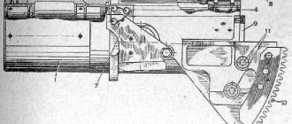
T-34 TANK MANUAL CHAPTER TWO ARMORED CASE The armored hull and turret serve to accommodate the crew, weapons, and mechanisms of the tank and protect them from damage by rifle-machine-gun fire and shell fragments. Housing design Fig. 8. Tank body: 1— upper armor plate; 2— lower armor plate; 3— beam of the bow of the hull; 4— driver's hatch; 5— armored cap of the ball mounting of the machine gun; 6— plug above the shank of the tensioning mechanism worm; 7— sloth bracket; 8— hole for the balancer axis bracket; 9—cutout for the balancer pin; 10—platforms for rubber buffers; 11— racks of balancer limiters; 12— final drive housing; 13— inclined armor plate; 14—horizontal sheet. Rice. 9. Tank body (internal structure): 1— inclined suspension shaft; 2— lower inclined sheet; 3— final drive housing; 4— roof over the fighting compartment; 5—cutouts for the suspension shaft; 6— cover over the filler plug of the fuel tank; 7— fan baffle; 8— transverse sheet for fastening the gearbox; 9— towing hook. The tank hull (Fig. 8 and 9) consists of the following main parts: the bow, sides, stern, bottom, roof and transverse partitions. The bow of the hull. The bow of the hull (Fig. consists of the upper 1 and lower armor plates, fastened with a cast beam 3 . In the upper inclined sheet there is a hatch for the driver 4. It is closed with an armored cover on hinges. The cover (Fig. 10) is equipped with two vertical windows for viewing devices. It is locked with two bolts 1 on screws 14 fixed in the cover. When the cover is open, the locking are held by a ball stopper 15. In the middle part of the cover there is a self-locking lock 2, the body of which is welded to it. The body contains a spring, a pin with a pin and a handle for unlocking the lock. The hatch cover has a spring balancing mechanism that takes on the weight of the cover and makes it easier to open. With the help of a stopper, the cover is fixed in six positions.Fig. 10. Driver's hatch cover: 1— lid latching; 3— armored cover of the viewing device; 4— cover lever; 5— stem earring; 6— flange of the balancing mechanism; 7— outer spring of the balancing mechanism; 8— internal spring of the balancing mechanism; 9— support nut; 10— cover; 11— guide sleeve; 12— rod of the balancing mechanism; 13— bracket; 14— tightening screw; 15— locking stopper; 16— body of the balancing mechanism; 17—stopper and handwheel of the balancing mechanism The balancing mechanism consists of a housing 16, a rod 12 of the flange 6, two springs 7 and 8, a stopper with a handwheel 17, a support nut 9 and a cover 10 with a guide sleeve 11. The mechanism body is installed using a support nut on the bracket 13, welded to the roof of the tank hull. The rod has an earring 5 for connection with lever 4, welded to the hatch cover, and six cavities for the stopper tooth. When the lid is closed, the rod compresses the springs, which keep the lid from falling and hitting. When you open the lid, springs 7 and 8 tend to unclench and shake to lift it. To fix the cover, you need to rotate the handwheel and insert the stopper tooth into one of the depressions on the rod. The driver's viewing devices are two independent periscopic installations (Fig. 11). Each periscope device is a prism 19 made of silicate or organic glass. Devices for increasing visibility are located at an angle to the axis of the hatch with a turn towards the sides. The prism is enclosed in a tin frame with two leaf springs 18, pressed from below by a support 27, to which two leaf springs are welded and a handle is attached. At the top, the prism rests against a rubber or felt buffer 20, attached to the visor 22, and at the bottom it is pressed in by a cover 26. To protect the driver from fragments of the prisms in case of damage, a general protective glass 25 is installed. At the bottom, under the windows of the viewing devices, covers are attached that hold the prisms and protective glass from falling out. They are locked with a common lock 28 and, in addition, are fastened with a hook. To protect the prisms from bullets and shell fragments, they are covered on the outside with an armored cover. Each cover opens with independent drives located along the edges of the hatch. The drive consists of a rod 21 connected to the lid by a hinge, a fork, a lever with a welded cup in which a stopper with a spring is placed, etc. handle 29 connected to the stopper. The stopper, which fits into the holes of sector 30, can fix the cover in closed and three open positions. To reduce the possibility of damage to the prisms, keep the outer covers slightly open. Soft headbands 23 and 24, installed above the protective glass and on an inclined sheet, protect the driver’s head from bruises. Rice. 11. Driver's viewing device: 18— prism leaf spring; 19—prism of the viewing device; 20—felt prism buffer; 21— drive rod for the viewing device cover; 22— visor; 23— forehead; 24— forehead; 25—protective glass; 26— prism cover; 27— support; 28— sealing the lids; 29— drive handle for the viewing device cover; 30—sector of the handle To replace the prisms or clean them from dirt, you need to turn the lock and, moving the hook to the side, open the corresponding bottom cover. Four spare prisms are stored in clips in the front box of the left fender liner. Two spare protective glasses are placed in a special box on the right bulwark. The polished surfaces of the prisms must not be damaged or contaminated. If the prisms and glass become dirty, immediately wipe them with flannel, cotton wool, a clean soft rag or thin (tissue) paper. In the upper inclined sheet (on the right side of the driver's hatch) there is a hole into which a welded armor cap is inserted for the ball mounting of the DT machine gun. At the bottom of the sheet there are two holes covered with armor plugs for access to the shanks of the worms of the track tensioning mechanism. Hooks with latches for towing the tank are welded next to these holes. The track tensioning mechanism is located inside the sloth brackets, which are welded to the beam in the bow of the tank and to the sides of its hull. The lower inclined sheet 2 is welded to the beam, sides and bottom. Brackets for attaching the suspension of the front rollers and the control panel are welded to the upper inclined sheet on the inside, and brackets for attaching compressed air cylinders are welded to the bottom sheet. On the inner surface of the bow sheets, in addition, there are welded bolts for fastening electrical wires and a number of other small parts. Hull sides Hull sides consist of upper inclined and lower vertical sheets. The top and bottom sheets are connected by horizontal sheets; At the joints, the sheets are connected by a weld. The lower vertical part of the side has five holes for the passage of the balancer axes (see Fig. in brackets 8), four cutouts 9 for the balancer trunnions, six welded brackets with platforms for attaching rubber buffers 10 that limit the rotation of the balancer, and five welded posts 11 for fastening balancer limiters. The idler brackets 7 are welded to the front part of the sides, and the final drive housings 12 are riveted and welded to the rear part. The upper part of the side is an inclined armor plate 13, which, together with the horizontal sheet 14, forms a fender liner. A shelf is welded along the entire fender liner above the caterpillar. The headlight brackets and two handrails for paratroopers are welded to the left inclined sheet. On the right inclined sheet there are also two handrails for paratroopers and an antenna input. Tools and accessories carried on the tank are attached to the inclined sheets and shelves above the track. Welded to the sides from the inside (see Fig. 9) eight shafts 1 (four on each side) for installing spring roller suspensions.
Tanks for fuel and oil are attached between the shafts, which are covered with bulwarks in the fighting compartment (they also serve to secure the ammunition rack). In addition, shields are attached to the sides in the bow to protect the front roller suspensions. Angles are welded to the inner edges of the inclined sheets, to which the roof over the engine and the top sheet of the stern are attached. Hull stern The hull stern consists of an upper inclined sheet, a lower inclined trough-shaped sheet 2 and two final drive housings 3. The lower inclined stern sheet is welded to the bottom with its lower edge, and with its side edges to the side sheets and final drive housings. Two hooks with latches 9 are welded to the outside of the bottom sheet for towing the tank. The upper inclined sheet (reclining) is attached to the body with three hinges and bolts. In the middle part of the sheet there is a round hatch covered with a lid, which serves to access the units installed in the rear part of the transmission compartment. On both sides of the hatch there are two openings through which the exhaust pipes pass. The latter are covered with armored caps attached to the sheet. Near each cap, one spare external fuel tank is attached to the armor plate. Bottom of the hull The bottom is the main fastening armor plate of the hull. It consists of two or four parts, joined end-to-end by a weld and reinforced with overlays. There are three hatches in the bottom, closed with armored covers. The front hatch (Fig. 12) is oval. It is located in the forward part of the bottom, at the feet of the radio operator, and serves as an emergency exit from the tank. A flange 5 is welded at the edges of the hatch, into which the cover 6 rests, connected to the bottom with a hinge 1. The cover is secured with four bolts 7, put on pins 10 screwed into the cover. The latches are pressed with nuts so that one end rests against the cover, and the other extends beyond the flange. When unscrewing the nuts, the locks are pressed at the top by springs 11. To quickly lock the hatch, use a latch 9, consisting of a body 2, a latch tooth 4 with a handle 8 and a spring 3. To open the hatch, you must: 1) loosen the nuts pressing the locks; 2) turn the bolts so that their ends come off the flange; 3) use handle 8 to release the latch and lower the hatch cover down. Rice. 12. Front hatch: 1— hatch cover hinge; 2— latch body; 3— latch spring; 4— latch tooth; 5— hatch flange; 6— hatch cover; 7— zadraka; 8— latch handle; 9— latch; 10— tightening pin; 11— drive spring. The middle sub-engine hatch is rectangular in shape, located in the engine compartment under the oil and water pumps and serves to access them. The hatch is closed with a lid, which is attached to the bottom with six bolts. The rear hatch (round) is located under the gearbox. It serves to drain oil from the box. The hatch is closed with a lid attached to the bottom with four bolts. There are eight cutouts along the edges of the bottom - four on each side. The cutouts are used for inspection and installation of roller suspensions. At the edges of the cutouts, on their inner side, the bases of the suspension shafts are welded. In the middle part of the bottom, under the oil tanks, two holes are cut out that serve for... draining oil from tanks. There are the same openings under the fuel tanks: two under the fighting compartment (left and right) and two at the rear of the tank. In the engine compartment there is a reinforced sub-frame on which the engine is mounted. Two supports for the brake brackets are welded into the transmission compartment. Ten brackets are located across the bottom. They serve as supports for the balancer axes. Plugs are welded to the inner end surface of the brackets to prevent lubricant from leaking out of the internal cavity. The two front brackets have windows for the passage of the lever connecting the front balancers to the suspensions. Hull roof The roof is divided into three parts: the roof over the fighting compartment, the roof over the engine and the roof over the transmission compartment. Rice. 13. Roof over the engine compartment: 1— middle longitudinal sheet over the engine; 2— side longitudinal sheet above the radiator; 3— armor strip; 4— hatch cover above the engine; 5— lid lock; 6—window for air passage to the radiator; 7— armored blinds. The roof over fighting compartment 4 (see Fig. 9) consists of one or two armor plates. It has a round cutout for installing the tower and holes for bolts for fastening the lower shoulder strap. In the sheets, above the shafts, there are two cutouts 5 for access to the upper part of the roller suspensions. The cutouts are covered with lids. In the front part, above the filler plugs of the fuel tanks, there are two holes, which are also closed with covers 6. The roof over the engine compartment (Fig. 13) is removable. It consists of a middle longitudinal sheet above the engine 1 and two side longitudinal sheets above the radiators 2. The middle sheet of the roof above the engine is trough-shaped, with a convex pointing upward. The side walls of the sheet are reinforced with welded armor strips 3. In the upper part of the sheet there is a hatch for access to the engine, closed with a hinged lid 4. The hatch cover is locked with a special lock 5. The front part of the middle roof sheet is attached with five, and the rear part with four bolts. Each longitudinal roof sheet is bolted to the middle sheet and to the body corners, so the roof over the engine compartment can be removed all at once or in parts. In the middle part of the sheets, located above the radiators, there are longitudinal windows 6 for the passage of air to them. The windows are covered with armored blinds. The blind sheet is fixed on two axes. Using a drive, it can be installed in three positions: horizontal, when the cutout is closed, vertical - with the cutout open, and in the middle - between one and the other positions. The blinds are installed in the desired position from the fighting compartment. Drive (Fig. 14). consists of a handle with a stopper 4, a sector 3, a shackle 5 and a rod 2. The rod, with its upper end, is attached to the ear of the blind axis 1, and the lower end to the shackle, which sits on the same axis with the handle. The handle stopper fits into the hole in the sector mounted on the front partition, fixing the position of the blinds. Each longitudinal sheet above the engine has three round holes covered with armored covers: the middle one for pouring oil into the oil tanks; and the side ones for lubricating the roller suspensions. Armor caps are installed over the blinds. The latter have grilles for air passage. At the same time, the grilles prevent large foreign objects from entering the tank. In the cap above the filling hole of the oil tank there is a cutout covered with an armored cover. A handrail for paratroopers is welded to the cap. The roof over the transmission compartment consists of two armor plates located above the fuel tanks (in the right sheet above the fuel tank filler hole there is a hatch closed with a lid), two armor plates for louvres, a narrow transverse armor plate and a hinged cap with a mesh that protects covers the roof over the transmission compartment, protecting it from foreign objects getting into it. Sheets of blinds can be installed and fixed in three positions using a drive. The drive to the blinds (Fig. 15) consists of a rod 6 connecting both sheets of the blinds 5, a longitudinal pull 2, a lever 3 with a handle having a stopper 4, and a sector 1. The sheets of the blinds are attached on axes to the sheets above the tanks. The drive handle 4 moves along sector 1, mounted on the left suspension shaft of the second support roller 7. Fig. 14. Blind drive above the radiators: 1— eye of the blind axis; 2— drive rod; 3—drive sector; 4— handle with stopper; 5— earring. Rice. 15. Drive to the blinds above the fan: 1—drive sector; 2— longitudinal thrust; 3— lever; 4— handle with stopper; 5— sheets of blinds; 6— rod connecting the sheets; 7— suspension shaft of the second road wheel. Transverse partitions of the hull The fighting compartment is separated from the engine compartment by an engine partition (Fig. 16). It consists of side non-removable sheets 2 and 12 and middle removable sheets 6 and 13. The side sheets in the lower part have cutouts through which batteries are installed and removed. The cutouts are closed with doors 1. On the right sheet there are: a syringe 4 for lubricating the water pump, a fuel distribution valve 3 and a sector with a drive handle for the blinds 5. On the left sheet there are: a door 9 for access to the fuses of the battery protection unit, a hole for a hose with a cable tachometer and tubes to thermometers 10, a manual oil pump 8 and a sector with a drive handle to the blinds 5. A signal 11 is attached to the upper left corner of this sheet from the engine compartment side. In the middle part of the upper removable sheet there is a hole for ventilation of the fighting compartment, covered with a mesh and a lid 7. There is a door at the top of the bottom removable sheet. A drive handle to the drain valve of the water pump is attached to the bar (between the upper and lower removable sheets); A sign with the inscription “Draining water” is attached above the drive handle. Rice. 16 Motor partition: 1— side leaf door; 2— fixed side sheet; 3— fuel distribution valve; 4— syringe for lubricating the water pump roller; 5— drive to the blinds above the radiators; 6—top removable sheet; 7— ventilation hatch cover; 8— manual oil pump; 9— fuse door of the battery protection unit; 10— hose with tachometer cable and tubes to thermometers; 11— electrical signal; 12— fixed side sheet; 13—lower removable sheet. Between the engine and transmission compartments there is (see Fig. 9) a fan partition 7. It has a round cutout for the fan rim with thin iron sectors welded to the edges of the cutout to reduce the gap between the fan and the partition. In the upper part of the partition, two holes were made through which exhaust pipes pass. In order to make it easier to remove the engine with a fan, the upper middle part of the partition is made removable. Behind the fan partition, the transverse sheet 8, to which the neck of the transmission change box is attached to the sides and to the sides. Dismantling of the case in order to remove the radiators, it is enough to remove the caps above the longitudinal blinds, disconnect the drive from the blinds and remove the longitudinal side sheets of the roof over the motor (the middle sheet of the roof is not required to be removed). To remove the roof located above the motor, it is necessary to remove the blinds above the fan and caps above the longitudinal blinds, remove the drive from the blinds, as well as remove the side longitudinal sheets of the roof, and then, rotating the tower, install (alternately) the neckline in it over each of Five screws fixing the sheet and turn them out. To remove the blinds installed above the fan, you need to unscrew two bolts located at the left side, and remove the sheets of the blinds to the left. In order to throw back the upper tilt sheet of the stern, it is necessary: to remove the armor caps above the exhaust pipes, remove these pipes, throw the grid over the blinds, remove the blinds, remove the wire of the “stop” lamp, turn the bolts that fasten the sheets above the feed tanks, as well as the bolts, Facing the rear leaf. It is impossible to throw a leaf sharply, otherwise it is possible to break it off the hinges. Carrying through the case after each exit is necessary: 1. Carefully clean the body outside of dust, dirt or snow. 2. Clean the body inside from water, dirt, snow, building, following in the winter to be not water, go the mud of ice in the deepening of the bottom under the fan. 3. Clean and lubricate all the loops and shutters of hatches with a thin layer of solidol. All rubber and grooved seals should always be in order. Gas and oil should not be allowed to enter them. Partitions must be tightly driven and reliably fixed, otherwise the normal operation of the system, engine cooling is disrupted. The tower in the rotating tower of the tank set weapons, place ammunition, surveillance devices. The rotating tower allows you to lead a circular fire from a gun and machine gun. In the tower there are a tank commander and a tower shooter. The device of the tower of the tank is cast, oblong in shape with a cylindrical base. It is installed on a ball support over the combat branch of the corps. The tower consists of a case and a roof with hatches and is equipped with a rotation mechanism and observation devices. Rice. 17. Tower (general view): 1 - neckline for a gun and a machine gun spawned with it; 2 - the castle of the hatch lid; 3 - observation gap; 4-a hole for the installation of periscopic sight PT-1-7; 5 - hatch cover; 6 - the lid of the hatch for ventilation; 7 - scum for shooting a tower; 8 - hinge loop of the hatch cover; 9 - capture; 10 - rubber buffer. The body of the tower (Fig. 17) The front wall of the tower is inclined. It has a rectangular neckline for the installation of a gun, twisted with a machine gun DT. Outside, the cutout is closed by an armored frontal shield with a neckline for a paired system. The frontal shield is attached to the tower with bolts. Brackets for trunnic troops are attached on the sides of the cut. On the right bracket there is a vertical platform for attaching the fast position of the gun, and on the left (in the lower part) - the guide hole for the lifting mechanism of the gun. On the side walls of the tower (in the middle part), two viewing slots 3, protected by the strips welded on the outside .. The cracks are equipped; viewing devices. The back wall is inclined. Together with the lateral walls and a cylindrical base, it forms a niche, where they put disks with cartridges for a machine gun in a special framework. In the rear wall of the niche there is a hole to strengthen the device for checking the rollback and rolling off the compressor of the gun. The hole is closed by a plug, fortified from the inside of the tower with a nut. In the tanks of the latest issues, the tower also has two holes for firing from a pistol, which are closed with plugs, stripping tower strengthened from the inside. The roof of the tower of the tower is a flat armored sheet welded to the tower body. There are four cutouts in the roof (Fig. 19). In the front of the roof (on the left side) in the round hole 1, the periscopic sight of the PT-4-7 is set, closed on top of the armor protection. Two hatches are equipped in the middle part of the roof - in the entrance and output of the crew, a removable jumper 5 is placed between them, which allows you to take outboard fuel tanks through the hatches without removing the towers. In the back of the roof (in the middle) there is a hatch 4 for ventilation with the edges struggled upwards. The hatch is closed by a cover welded on top with four cuts for air passage. For shooting the tower, four qma 8 (two in the front and two in the back of the roof) are equipped. 19. The roof of the tower (diagram): 1-a hole for the installation of the periscopic trailer PT-4-7; 2 - hatch; 3 - hatch; 4 - hatch for ventilation; 5 - removable jumper; 6 - capture; 7 - hinge loop; 8 - rym; 9 - castle. The hatches of the hatches are attached to the roof of the tower using hinged loops 7 with captures 6, holding them in an open position. For the reliability of holding open covers when moving the tank, a rubber buffer is installed. The hatches are locked with locks 9. The castle 9 has a case in which a latch with a handle and a spring are placed. When closing the lid, the latch, squeezing the squad, enters the body, the castle. To unlock the lock from the inside, you need to remove the latch with a handle by the edge of the supporting site. Outside, the castle, if it is not stained, is unlocked by the key. If it is stained, then it is impossible to unite it outside. In order to lock the lock, you need to turn the castle handle up and stall it with a button; At the same time, the pen will be reproached to the limiter welded to the hatch cover at the castle body. To prevent the locking of the lock, you need to throw the handle onto the limiter. To facilitate opening the covers, the latter are balanced by the spring. Rice. 20. The observation device of the tower: 1 - damper; 2 - rubber hardshop; 3 - shield; 4 - protective glass; 5 - body cover; 6 - the handle of the damper; 7 - the body of the device; 8 is a plate spring. The tower of the tower of the tower has two lateral viewing devices (Fig. 20), which consist of housing 7, housing cover 5, shutters 1, rubber tanker 2, shield 3 and protective glass 4. Building 7 are welded to the tower so that its cutout is located Against the gap of the tower. The case is closed with a lid 5. Between it and the lid is placed a shuttle 1, held in the upper position with a plate spring 8. The damper serves to close the observation slit. A 3 with a rubber pitch 2 in the upper part is strengthened to the lid. Between the lid and the shield, against their windows, the protective glass 4 is installed, which protects the eyes of the observer from lead spray. Two spare windows and flannel wiping to them are stored in the side pocket of the bag on the right side of the tank. To use the observation device, pull the shuttle handle 6 down, which will open the observation target. Rice. 21. Balloon support of the tower: 1 - lower shoulder strap; 2 - ball; 3 - separator ring of balls; 4 - supporting ring; 5 - upper shoulder strap; 6 - capture; 7 - shield of fence. The ball support of the tower of the ball support of the tower (Fig. 21) ensures the ease of rotation of the tower around its vertical axis. The support of the lower shoulder strap 1, the upper shoulder strap 5 and 120 balls 2 in the separator ring 3. The lower and upper shoulder straps are a flat ring with a bacter that limits the movement of balls in the radial direction. There is an angular circle for shooting from closed positions on the uniform. The lower shoulder strap is installed on the roof of the tank. On its inner circle there is a gear crown with which the gear of the rotary mechanism of the tower is hooked. The upper shoulder strap is attached to the support ring 4, welded to the tower. The sectors of the capture 6, covering the end of the lower shoulder strap are attached to the punch, which protects the tower from overturning. The gear crown of the epaulettes is fenced with ring shields 7 attached to the upper shoulder strap. To ensure the normal operation of the ball support, it is necessary to lubricate the begs abundantly; Paths and balls: in the warm time by solidol, and in winter a mixture of 50% of the solidol and 50% of the air -MAZ. Rice. 22. Stop of the camping position of the tower: 1 - Stop Corps; 2 - comb; 3 - stopper; 4 - locking screws; 5 - installation screw. A lock of the camping position of the tower in the posterior capture located between the backs of the seats is mounted by the stopper of the tower (Fig. 22), which consists of the following main parts: a stamped case 1 with a capture, a comb 2 with an internal threaded hole, an axis of the stopper 3 and two locking screws 4 , installation screw 5 and pens. The Stop -Stop case has a cylindrical hole, which includes a comb with an axis wrapped in it. A handle is put on the square end of the axis, fixed by stop screws 4. When rotating the handle of the rowing, the stopper is hooked with the teeth of the shoulder strap and stops the tower in any position. Rice. 23. The rotary mechanism of the tower (general view). The rotary mechanism of the tower is the rotary mechanism (Fig. 23 and 24), with which the tower rotates, is located on its left side and is attached to the upper stimure 9 and to the 42 bracket in the tower body. Using the rotary mechanism, the tower can be rotated manually and using an electric motor. In the manual method, the speed of rotation of the tower depends on the speed of rotation of the flywheel, when rotating using an electric motor - on the number of revolutions of the latter. It is approximately divided into three steps: the first stage 2 ... 3 rpm, the second stage 3 ... 4 rpm and the third stage 4 ... 6 rpm. Using a rotary mechanism, the tower can be rotated both clockwise and counterclockwise. The rotary mechanism device is mounted in the connecting crankcase 1 and 2 at the upper part of which there is a tide for installing an electric motor. The 44 electric motor is fastened with two ribbons, the ends of which are fixed in the ears of the crankcase. The electric motor has a 24 rheostat with a 45 handle and a 46 button of the stopper of the handle. To rotate the tower by an electric motor, you need to click the stopper of the handle and turn the handle in the direction in which you need to rotate the tower. The rotation of the electric motor roller is transmitted through the elastic couplings 23 with the rubber ring of the drive gear 21, which is strengthened on the leading roller 22, installed on two ball bearings 34. The drive gear through a parasitic gear 20, rotating on the ball -bearing, reinforced on the axis, rotates the driven gear 18, and together together, and together With her, the worm 17, on which it is installed on the veneer. All three gears are enclosed in the casing 19, which is attached to the upper crankcase of the rotary mechanism. The worm, made at the same time with the shaft and installed on two balls 37, rotates the worm gear 16, which is strictly connected to the figure gear 15, which rotates satellites 13. satellites 13, rotated. figured gear, rotate the gear with the inner tooth 10, planted on the veneer in the middle part of the shaft 3. The lower neck of the shaft 3 is located in the sleeve 29, pressed into the lower crankcase 2, and the upper part is fixed in two ball bearings 28, one of which is placed in the shank of the figure gears. At the lower end of the shaft 3 protruding from the crankcase, the gear 4 is strengthened using the friction clutch, linked to the tower 8. Having received rotation from the shaft, the gear 4 is rolled up according to the motion -free preparation of 8, and the tower rotates relative to the tank body. The friction coupling protects the rotary mechanism from shock loads that occur both when the tower rotation engine is turned off, and when it is turned on and with possible strokes of the barrel. The friction clutch consists of two cones 5 and 6, sitting on the shaft slots 3. The cones enter the gears linked to the shoulder strap and pressed from below with a spring 7. The friction clutch is closed with a casing 55. To rotate the tower, you need to turn the handle of the flywheel 25 rotary mechanism, strengthened, strengthened On a manual drive worm 12. A manual drive 12 rotates a worm gear twin with it 11. A disc with a hub 32 will be put to the end of the worm gear 11, on which the inner clip of the ball bearings 27, pressed to the disk with a nut. The outer clutch of the ball bearing is installed in the lower, crankcase 2. The worm gear 11 is freely planted on a gear with an inner tooth 10. Having received rotation from the worm 12, the worm gear 11 captivates the satellites 13 and roller them around the curly gear. A figured gear is motionless, since it is connected to the worm of the electric drive 16, braking worm 17. Satelites, rolling around around a curly gear, rotate a geegeon with an inner tooth 10, which rotates the shaft transmitted through the friction coupling of the six, which is rolled up by the six The gear rake of a motionless shoulder strap and rotates the tower. Rice. 24. The rotary mechanism of the tower (in the context): 1 - the upper part of the crankcase; 2 - lower part of the crankcase; 3 - shaft; 4 - gear; 5 - the upper cone of the friction coupling; 6 - the lower cone of the friction coupling; 7 - a spring of cones; 8 - lower shoulder strap; 9 - upper shoulder strap; 10 - gear with an inner tooth; 11 - worm gear of a manual drive; 12 - manual drive worm; 13 - satellite; 14 - axis of satellite; 15 - figured gear; 16 - worm gear of an electric drive; 17 - electric drive worm; 18 - driven gear; 19 - casing; 20 - parasitic gear; 21 - Leading gear; 22 - leading roller; 23 - elastic coupling; 24 - rheostat of an electric motor; 26 - the handle of the flywheel; 26 - the disk of the lower crankcase; 27 - ball bearing; 28 - ball bearing; 29 - sleeve of the lower crankcase; 30 - gasket; 31 - flange; 32 - a disc with a hub; 33 - gasket; 34 - ball bearing, 35 - casing; 36 - cover; 37 - ball bearing; 38 - ring; 39 - Carter of a manual drive worm; 40 - crankcase lid; 41 - gasket; 42 - bracket of the tower body; 43 - ring; 44 - electric motor; 45 - the handle of the rheostat; 46 - the button of the stopper of the handle. The installation of the rotary mechanism should be reliably strengthened - its shakiness is unacceptable. When installing the rotary mechanism under the bonnons of the upper and lower bolts attaching the rotary mechanism, gaskets are installed to adjust the gear engagement with the shoulder strap. It is necessary that the teeth in the hook, when rolled by the gear 4, adjoin the entire width. The correctness of the gear gear with the lower shoulder strap is checked by the rotation of the tower 360 ° in both directions with the tank's roll or with a rise of up to 10 °. The tower should rotate freely, without jamming and seizing. The gap between the teeth of the gear of the mechanism and the lower shoulder strap should be no more than 0.7 mm. On the rise of up to 10 °, the tightening of the spring of the gear friction spring is also checked, and the friction slipping is unacceptable. When slipping, it is necessary to tighten the nut that presses the spring with a little effort. The magnitude of the force is determined by the height of the spring: the protracted spring should have a height of 32 ... 32.5 mm. Seats in the tower in the tower, on both sides of the gun, two folding seats are installed, the height of which can be adjusted. The left seat is occupied by the commander of the tank, the right commander of the tower. The seats can be installed in height in three positions and in any of these provisions are fixed with a locking bolt. The seat pillow is thrown into a vertical position with two springs. Chapter One General Description Chapter Second Armor Corps Chapter Third Arms Chapter Fourth V-2-34 System System System System System Cooling System Chapter Fifth Transmission General Friction Gearbox Board Fiction Chapter Sixth Cassopian Chapter Seventh Electrical Electrical Electrical Electrical Conducting General Information Sources of current consumers Consumer Eight-eighth communication Chapter ninth maintenance of tank refueling technical inspections lubrication of the tank winter and summer operation operation of the tank tank S-53 Additional instructions of the application
Tank battles in World War 1 and World War 2. Performance characteristics of tanks in World War 1 and World War 2.
T-34 turrets were installed on armored trains and armored boats
The war is over home page
URL ?>