History of creation
The creation of a new version of the weapon began shortly after the end of the Great Patriotic War, which showed the shortcomings of the TT pistol and Nagan revolver, which were in service with the Red Army. The condition of the competition, held in 1947-48, was the creation of a pistol with a design similar to the German Walter PP of the 1929 model.
Initially, two calibers were provided for the weapon - 7.65 and 9 mm, but the first was quickly abandoned. For the 9 mm caliber, a domestic PM cartridge with a size of 9*18 was developed, which was slightly larger and more powerful than the “Walter” original.
The main advantages of such a cartridge were a greater stopping effect (compared to 7.62*25 from the TT) and the possibility of using a simplified automatic circuit with a fixed barrel and a freely moving bolt in the Makarov pistol.
The designs of many gunsmith designers were entered into the competition, among whom were the famous names F.V. Tokareva, S.A. Korovina, S.G. Simonov and many others. N.F. also presented his project. Fedorov.
Pistols, Mauser, Beretta and a number of others acted as opponents to these designs.
According to all test results, the best performance was found in the design of the Makarov pistol of 9 mm caliber, which was recommended for mass production, as well as for adoption under the designation PM. The designer managed to perfectly calculate the relative position of the cartridge relative to the chamber and the optimal geometry of the mating parts.
Thanks to this, it was possible to completely avoid the problem of jamming in the inclined part of the chamber. Since 1951, supplies of 9 mm PM began for the needs of the army and police. Thus began the gradual displacement of TT pistols.
Shutter cover of the Makarov "PM" pistol
It is a combination of two parts into one whole: the barrel casing and the bolt itself. This has a positive effect on automatics with blowback recoil, as it increases the weight of the bolt. The bolt casing has a transverse groove on the outside for the movable rear sight, a notch to eliminate glare when aiming, a window for ejecting spent cartridges, a groove for the ejector and a socket for its spring, a socket for the fuse and recesses for its fixation, a notch for ease of retracting the bolt to the rear position , groove for the trigger. Inside, the bolt casing has a channel for the barrel, longitudinal projections for moving the bolt casing along the frame, a groove for the reflector, a groove for the release protrusion of the cocking lever, a cartridge rammer into the chamber, a cup for placing the bottom of the cartridge case, a protrusion for separating the cocking lever from the sear, a recess for placing the release ledge of the cocking lever when the trigger is pressed, a channel for placing the firing pin.
Composite parts
The pistol was supplied with a set of accessories, consisting of a spare clip, a kit for cleaning and wiping parts, as well as a holster with a safety strap. The design of the pistol is quite simple, thanks to which it consists of only fourteen main parts.
Complete disassembly will divide the weapon into a larger number of parts - 32.
The PM pistol includes the following key components:
- One-piece frame including barrel and trigger guard. The barrel is installed with tension using a press into the body part of the frame and is additionally secured with a pin. This unit is non-separable. Some pistols were equipped with frames of a special lightweight design - with several drilled holes.
- The bolt part, which includes a firing pin, a safety element and an ejector. The last part is used to remove empty, spent cartridges.
- A spring that carries out the return stroke of the shutter.
- The mechanism that is responsible for the functionality of the striker.
- A facing handle that is attached to the frame with a screw.
- Shutter delay.
- Replaceable magazine located inside the handle.
Many parts used in the PM design have a dual purpose. For example, bolt stop parts are used as a device for deflecting cartridges. Due to its special shape, the mainspring is used to support the cocking lever, as a sear drive spring, and to retract the hammer when the weapon is put on safety. The lower part of this spring is used for the magazine latch mechanism.
Shot from a Makarov "PM" pistol
To fire a shot you must: turn off the safety; cock the trigger; pull the trigger. When the safety is turned off: the safety protrusion rises, releasing the trigger; the hook comes out of the trigger protrusion, releases it and allows the trigger to move back; the shelf of the ledge on the fuse axis releases the sear; the sear, under the action of its spring, moves down slightly, and the nose of the sear becomes in front of the safety cock; the trigger is put on safety cock (“release” of the trigger); the fuse rib extends beyond the left protrusion of the frame and separates the bolt from the frame. When cocking the hammer, the sear, under the action of its spring, jumps with its nose behind the cocking lever and keeps the hammer cocked. When the trigger is turned by the front part of the annular recess, it shifts the trigger rod with the cocking lever forward and slightly upward, due to which part of the free play of the trigger is selected. When the lever is lifted up, its cutout approaches the protrusion of the sear. When you press the trigger, the following happens: the trigger rod moves forward; the cocking lever, connected to the rear end of the trigger rod, rotates on the rear axle of the trigger rod and rises until its cutout rests against the protrusion of the sear, and then lifts the sear up, disengages it from the cocking hammer and inserts its release protrusion into the recess shutter; the trigger, under the action of the wide feather of the mainspring, turns and strikes the firing pin; the firing pin, having received a blow from the trigger, moves forward and breaks the primer with the striker; shot. Under the influence of recoil force, the bolt moves backward. In this case, the following happens: the bolt with its protrusion displaces the release protrusion of the cocking lever, disengaging it from the sear; the release protrusion of the cocking lever slides along the bolt groove; the ejector, with its hook, removes the cartridge case from the chamber and holds it in the bolt cup until it meets the reflector; When the cartridge meets the reflector, it is removed from the pistol through the window of the bolt casing; the trigger is pulled back under the action of the bolt; the sear, freed from the action of the cocking lever, is pressed against the trigger under the action of its spring, and when the trigger turns all the way, the nose of the sear jumps behind the cocking cock and holds it until the next shot; The feeder, under the action of its spring, lifts the next cartridge until it stops at the edges of the magazine on the side walls, thus placing it in front of the bolt rammer. When the bolt returns to the front position under the action of the return spring, the parts work in the same way as with manual loading. To fire the next shot, you must release the trigger and press it again. When the trigger is released, the trigger rod with the cocking lever, under the action of the narrow feather of the mainspring, will move back and the protrusion of the sear will enter the cutout of the cocking lever. When you press the trigger, the cocking lever will raise the sear and release the hammer from the sear again - the next shot will fire, etc.
Scheme of work
After installing the magazine, the bolt pushes the cartridge into the chamber cavity. The cartridge is loaded from the tapering upper part of the clip. Then the PM is put on safety.
To carry out this operation, a flag switch is installed on the left side of the shutter. This device removes the trigger from the cocked position and completely blocks its movement. At the same time, the trigger element of the pistol is also fixed. An additional lock on the safety mechanism completely blocks the bolt. When carried in a holster, the PM must always be with the safety on.
Before firing, the PM must be removed from the safety lock. The pistol is taken in the right hand, and the flag moves down, where it enters the “fire” mode. In this case, the pistol trigger is automatically set to a special safety cock.
Pulling the front of the trigger for the first time requires a lot of force - about 3.5 kg. This is due to the fact that when pressed, the hammer is cocked.
The following shots require less effort (no more than 1.5 kg), since the hammer will be cocked by the force of the powder gases. For more accurate aiming during the first shot, the trigger has a manual cocking function. At the same time, it is moved downwards with your finger, and the trigger goes a little deeper, towards the handle.
If necessary, the trigger is removed from combat mode manually. To do this, the shooter recesses the trigger, while at the same time restraining the movement of the trigger with his thumb. After releasing the hook, it will take the safety position. Due to the rod system, it will put the trigger in the same position.
The mechanics of the Makarov pistol work as follows:
- When you press the trigger with your finger, it will move back and move the trigger, which will sharply set the firing pin in motion.
- The firing pin destroys the primer located at the bottom of the cartridge case and ignites it.
- The flash from the primer is transmitted to the main charge of gunpowder, which burns and produces a large volume of gases.
- The gases force the bullet through the barrel and exert opposing pressure on the bottom of the cartridge case.
- The sleeve carries the bolt with it, which begins to move backward. This causes the return spring to be compressed.
- The cartridge remains in the ejector until it comes into contact with the reflector. After this, it is thrown out to the right side.
- The shutter continues to move until it reaches the rearmost point, at which it turns the trigger on the axis and sets it to cocking mode.
- Then, under the force of a compressed spring, the shutter begins to move back.
- During movement, the bolt, using the rammer on it, captures the cartridge from the clip and sends it into the chamber of the barrel.
- At the end of the stroke, the bolt locks the barrel. Since the bolt and barrel do not have any connection, the barrel bore is locked solely by the mass of the bolt itself and the force of the return spring.
- The shooter presses the trigger again and the next shot is fired.
After firing the last cartridge from the clip, the shutter enters the delay mode. After installing a new clip, the delay is removed using the lever on the left side of the pistol frame. In this case, the first cartridge from the clip is fed into the chamber. The magazine installed in the handle is secured with a latch located at the bottom of the handle.
This design completely eliminates the possibility of spontaneous removal of the clip when carrying or when removing the pistol from the holster cavity.
Starting position of the Makarov pistol "PM"
The shutter casing is in the extreme forward position, the return spring has the least compression. The trigger is released, under the action of the wide feather of the mainspring, it is pulled back somewhat (“release” the trigger) and put on the safety cock; both mainspring feathers have the least amount of compression. The trigger is in the extreme forward position. The trigger rod with the cocking lever, under the action of the narrow feather of the mainspring, moves to the rearmost position; The self-cocking protrusion of the cocking lever is engaged with the self-cocking tooth of the hammer so that when the trigger is pressed, the hammer is self-cocked. The magazine is inserted into the handle; the feeder is in the upper position, resting against the ridge of the bolt; the feeder hook presses on the slide stop so that when the bolt is pulled back, the front end of the slide stop will be raised up by the feeder.
Weapon maintenance
To clean and check the condition of the components, the Makarov pistol is partially or completely disassembled. Such procedures are one of the main conditions for maintaining a weapon in good condition.
In combat or training situations, cleaning must be carried out daily. After firing with blank or live cartridges, the bore and chamber cavity are cleaned immediately. Regular daily cleaning should then be carried out over several days.
When storing a pistol, the owner should carry out preventative weekly cleaning of the weapon.
Before lubricating, the surface of the weapon should be thoroughly wiped to remove any remaining moisture. The main types of lubricant are liquid gun lubricant or a special RFC solution used to clean the bore in barracks conditions.
After washing with the solution, the weapon is wiped with a rag and lubricated. Caring for a holster for a Makarov pistol involves regularly wiping it with a soft cloth on all sides to remove traces of water and dirt.
The sequence of steps for partial disassembly is as follows:
- Press the latch with your finger, pull the clip by the lower protrusion with another finger and pull the clip out of the handle.
- Turn off the fuse.
- To check that there is no cartridge in the inside of the chamber, you must move the bolt all the way back. After locking the bolt for delay, you must visually check the chamber.
- Release the shutter from delay mode.
- Move the trigger guard down a little and then move it to the left. The bracket should rest against the frame and remain in this state in the future. Additional retention of the bracket during disassembly is carried out with the finger of the right hand.
- Then you should remove the bolt from the pistol frame. Initially, it is pulled all the way back, while simultaneously lifting it by the back side. During movement, the bolt will move forward slightly under the influence of the compressed spring and will be removed from the frame.
- Install the trigger guard in its original place.
- Remove the return spring installed on the surface of the barrel. The part is removed with rotational movements. When reassembling, be sure to put it back in place correctly. The reference point is the front turn, which has a reduced diameter.
- Clean and lubricate parts.
- Assemble the pistol in the reverse order of disassembly.
When installing the valve in its original place, the end of the spring should be inserted into the channel in the valve. Then you should pull the shutter all the way back, keeping the back part raised.
At the rear point, the bolt is lowered by inserting the existing hooks into special grooves on the pistol frame. Then the bolt part is released, and it sharply returns to the location of the extreme forward point under the influence of a spring. When installing the shutter in place, it is not necessary to move the bracket to the side.
For more thorough inspection and cleaning, complete disassembly is used. The instructions do not recommend carrying out such an operation too often, since it leads to wear and tear on the material part of the Makarov pistol.
The main reasons for complete disassembly are the long exposure of the gun to precipitation, in conditions of heavy dust and before using a new type of lubricant.
When performing such work under normal conditions, it is performed on a table or any flat surface. Disassembly of weapons in the field is carried out on a clean substrate.
Complete disassembly is a logical continuation of incomplete disassembly and consists of several stages:
- Removing the sear and mechanism for delaying the shutter from the frame. To do this, you should gently pull the trigger, braking it with your finger. Remove the tip of the sear spring from the mounting point on the bolt delay. Removal is carried out using a special protrusion located on the wiping rod included in the tool kit. Then you should rotate the sear body until the plane on the right trunnion aligns with the counter slot in the frame body. At the next stage, you will need to lift the parts up and carefully remove them from the frame.
- Separating the handle and mainspring from the frame. To remove the handle, you need to unscrew the screw. The wiper rod or shutter delay reflector acts as a screwdriver. After unscrewing the screw, the plastic housing of the handle is pulled down. To dismantle the spring, it is pressed against the base of the handle and then moved down along it. At the same time, the spring valve is removed and it itself is separated from the boss made on the lower part of the handle (on early releases of the PM there is no valve).
- Disconnecting the hammer from the trigger, as well as the trigger rod and the lever used for cocking. Before starting this stage, move the hook to the maximum forward position all the way, while simultaneously turning the trigger forward. When turning, special planes made on the trigger axes must coincide with the mating surfaces on the pistol frame. At this moment, the trigger moves towards the barrel and is then removed from the frame. Then you should lift the end of the rod from the trigger with your fingers, and then remove the pin from the counter hole. Return the trigger guard back down, turn the hook slightly forward and remove it from the guide pins in the frame. After removing the hook, return the bracket back.
- Removing the safety device, firing pin and cartridge ejector from the bolt body. To do this, set the fuse box in the upper position, move it to the side and remove it from its seat. Tapping the bolt on your palm, remove the pistol's firing pin from its place. Place the bolt on a hard surface, press the wiping rod into the bends (the rod on which the spring fits) of the cartridge ejector. Rotate the partially recessed part around the clamp and remove. Then you should remove the oppression itself with the spring attached to it.
- Disassembling the clip into its component parts. In this case, a spring and a plate are removed from the magazine, which serve to feed cartridges to the chamber. After completing all the planned work, assembly is carried out in the reverse order. Regardless of the type of disassembly, the gun is checked upon completion. The checks include removing and re-engaging the safety, as well as checking the functionality of the bolt stop.
Makarov PM pistol.
N.F. Makarov
Purpose of the Makarov PM pistol.
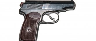
9 mm Makarov pistol
is a personal weapon of attack and defense, designed to defeat the enemy at short distances.
Fire from a pistol is most effective at distances of up to 50 m. The destructive power of a bullet is maintained up to 350 m. Fire from a pistol is carried out in single shots. The pistol's combat rate of fire is 30 rounds per minute. The weight of the pistol with a loaded magazine is 810 g. 9 mm pistol cartridges are used for firing the pistol. The initial speed of the bullet is 315 m/s. When firing, cartridges are fed into the chamber from a magazine with a capacity of 8 rounds.
General design of the pistol
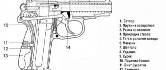
Gun
consists of the following main parts and mechanisms ■ frame with barrel and trigger guard; ■ bolt with firing pin, ejector and fuse; ■ return spring; ■ firing mechanism; ■ handles with screw; ■ shutter stop; ■ store.
9 mm pistol cartridge
consists of a cartridge case, a primer, a powder charge, and a bullet.
The sleeve
serves to place the powder charge and connect all parts of the cartridge;
during a shot, it prevents the breakthrough of gases from the barrel bore through the chamber. At the bottom of the sleeve there are: a slot for a primer; an anvil on which the primer is struck; two seed holes through which flames from the percussion composition of the primer penetrate to the powder charge. Outside, at the bottom of the sleeve, there is an annular groove for hooking the ejector. The charge
consists of smokeless pyroxylin powder.
The capsule
serves to ignite the powder charge.
It consists of a brass cap with shock compound pressed into it and a foil circle covering the shock compound. When the striker strikes, the impact composition ignites. The bullet
consists of a bimetallic (clad) shell into which a steel core is pressed. There is a lead jacket between the bullet and the steel core. Cartridges for loading the pistol are loaded into an 8-round magazine. The magazine is loaded by inserting and retracting the cartridges by hand. The cartridges are sealed in standard wooden cartridge boxes of 2560 pcs. in everyone. Each box contains two rolled-up iron or sealed galvanized boxes, in which cartridges are placed in cardboard packs, 16 cartridges per pack. One iron box holds 80 cardboard packs. On the side walls of the wooden boxes there are inscriptions indicating the nomenclature of the cartridges placed in these boxes: the batch number of the cartridges, the month and year of manufacture of the cartridges and gunpowder, the manufacturing plant, the brand and batch of gunpowder, the number of cartridges in the box.
It is important to know:
The weight of one box of cartridges is about 33 kg.
Designed to destroy manpower at a range of up to 50 m. Used when firing from a PM pistol, PMM pistol, silent pistol at a distance of up to 50 m, from a Stechkin pistol (APS) - up to 200 m. When designing the cartridge, the cartridge case was taken as the basis TT 7.62x25 mm, “cut” at 18 mm from the bottom. This decision made it possible, on the one hand, to use machine tools and measuring equipment for TT cartridges, and on the other hand, it excluded the possibility of using new cartridges for Soviet weapons that remained in the hands of the population after the war. Initially, the cartridge case was made of brass, and the jacketed bullet had a lead core pressed into a steel shell clad with tombac. Currently, the cartridge has a bimetallic sleeve and a bullet with a mushroom-shaped steel core enclosed in a lead jacket. Lead jacketed steel core bullet
saves lead and increases the ability to penetrate non-metallic barriers (wood, soft body armor). At the same time, when it hits a dense barrier (concrete, steel), the bullet casing is destroyed, and the core, due to the round shape of the head, ricochets strongly. As a result, such a bullet cannot penetrate body armor with steel plates. In addition, the steel core reduced the mass of the bullet, which worsened its ballistic characteristics compared to a bullet with a lead core. In the 90s, the production of cartridges with a varnished steel case (Pst GS) began.
9mm lead core cartridge
produced for export by the Novosibirsk Low-Voltage Equipment Plant (bullet weight - 6.1 g, initial speed - 315 m/s), Tula Cartridge Plant (bullet weight - 6.86 g, initial speed - 303 m/s), Barnaul Machine Tool Plant ( bullet mass - 6.1 g, initial speed - 325 m/s). Designed to engage manpower at a distance of up to 50 m. Used when firing from a 9mm PM pistol, 9mm PMM pistol.
9 mm cartridge with tracer bullet (PT)
produced by the Novosibirsk Low-Voltage Equipment Plant. Designed for firing from all types of weapons that use a standard Makarov pistol cartridge (PM, PMM, APS). A tracer bullet allows for fire adjustment and psychological impact. The distinctive color is green varnish.
Designed for firing from pistols PMM, "Berdysh", submachine gun "Klin", "Bison-2".
It was created by modernizing the 9x18 57-N-181s cartridge, in connection with the widespread use of body armor and the trend that emerged in the late 80s to offer consumers compact high-power pistols with increased-capacity magazines. The modernization consisted of placing a larger charge of gunpowder into the case of the previous 9x18 57-N-181s cartridge, as well as changing the shape of the bullet. By improving the ballistic properties, the initial speed and muzzle energy of the bullet, as well as its penetrating and stopping effect, increased. To reduce the possibility of ricochets, the conical head of the bullet has a flat shape.
Designed for firing from PM.
The 9 mm SP-8 cartridge is designed for firing when minimal destruction of low-strength barriers is necessary. Produced by the Klimovsky stamping plant.
Designed to destroy manpower.
Used when shooting from PM. The color of the bullet is black on the tip. Bullet with polyethylene plug. Produced by the Klimovsky stamping plant.
9-mm armor-piercing cartridge (AP)
produced by the Novosibirsk NVA plant. KBP employees have developed a 9x18 cartridge, the bullet speed of which at a distance of 10 m from the muzzle is 470-480 m/s. At the same time, due to the reduction in bullet mass, the recoil impulse when firing is almost equal to the recoil impulse when firing a standard 9-mm pistol cartridge 57-N-181s. The bullet is semi-jacketed, with a bare steel core and an aluminum jacket that fits the core on the sides. The low mass of the bullet at a high initial speed (compared to a standard cartridge) made it possible at distances up to 25 meters to increase its kinetic energy when meeting an obstacle. The field tests of the cartridge that have begun have demonstrated its undeniable advantage in almost all combat characteristics over previously proposed options. The bullet of the developed cartridge penetrates a general-arms protective vest model 6B5-12 at a distance of 30 meters with a probability of 100%, and a 5-mm steel sheet at a distance of 15 meters with a probability of 80%.
Cartridges with increased ballistic characteristics.
Intended as standard ammunition for the Kedr, Klin, and Cypress submachine guns adopted by the Ministry of Internal Affairs.
They are distinguished by increased impulse. They have an ogive, i.e. cone-shaped to improve ballistic characteristics. He is the main patron of the Ministry of Internal Affairs.
The procedure for partial disassembly and assembly of the pistol
Disassembling and assembling the pistol
Disassembly of the pistol may be incomplete or complete. Partial disassembly is carried out for cleaning, lubricating and inspecting the gun, complete - for cleaning when the gun is heavily soiled, after it has been exposed to rain or snow, when switching to a new lubricant, as well as during repairs. Frequent complete disassembly of the pistol is not allowed, as it accelerates the wear of parts and mechanisms.
Incomplete disassembly of the pistol
1)Remove the magazine from the base of the handle
(Fig. 5). Holding the pistol by the handle with your right hand, with the thumb of your left hand, pull the magazine latch back as far as it will go, while simultaneously pulling back the protruding part of the magazine cover with the index finger of your left hand, remove the magazine from the base of the handle. Check to see if there is a cartridge in the chamber, to do this, turn off the safety (move the flag down), move the bolt to the rear position with your left hand, place it on the bolt stop and inspect the chamber. Press the shutter stop with your right thumb to release the shutter.
2)Separate the shutter from the frame.
Taking the pistol in your right hand by the handle, with your left hand pull the trigger guard down (Fig. 6) and, tilting it to the left, rest it against the frame so that it is held in this position.
During further disassembly, hold it in this position with the index finger of your right hand. With your left hand, move the bolt to its rearmost position and, lifting its rear end, allow it to move forward under the action of the return spring. Separate the bolt from the frame
(Fig. 7) and put the trigger guard in its place.
3)Remove the return spring from the barrel.
Holding the frame with your right hand by the handle and rotating the return spring towards you with your left hand, remove it from the barrel.
Reassembling the pistol after partial disassembly
1)Place the return spring on the barrel.
Taking the frame by the handle in your right hand, with your left hand you must put the return spring onto the barrel with the end in which the outermost coil has a smaller diameter compared to other coils.
2) Attach the shutter to the frame.
Holding the frame by the handle in your right hand and the bolt in your left, insert the free end of the return spring into the bolt channel (Fig. and move the bolt to the rearmost position so that the muzzle of the barrel passes through the bolt channel and protrudes outwards (Fig. 9). Lower the rear end of the bolt onto the frame so that the longitudinal protrusions of the bolt fit into the grooves of the frame, and, pressing the bolt against the frame, release it. The bolt, under the action of the return spring, vigorously returns to the front position. Turn on the safety (lift the flag up).
It is important to know:
To attach the shutter to the frame, it is not necessary to pull down and twist the trigger guard. At the same time, when moving the bolt to the rearmost position, it is necessary to lift its rear end up as far as possible so that the lower front wall of the bolt does not stick into the ridge of the trigger guard, which limits the movement of the bolt back.
3)Insert the magazine into the base of the handle.
Holding the pistol in your right hand, use the thumb and forefinger of your left hand to insert the magazine into the base of the handle through the lower window of the base of the handle (Fig. 10). Press the magazine cover with your thumb so that the latch (the lower end of the mainspring) jumps over the protrusion on the wall of the magazine; there should be a click. Hitting the magazine with the palm of your hand is not allowed. Check that the gun is assembled correctly after partial disassembly. Turn off the fuse (move the flag down). Move the shutter to the rear position and release it. The shutter, having moved slightly forward, engages the slide stop and remains in the rear position. Press the shutter stop with your right thumb and release the shutter.
The bolt, under the action of the return spring, must vigorously return to the forward position, and the trigger must be cocked. Turn on the fuse (raise the flag up). The trigger must be released from cocking and locked.
Purpose and structure of pistol parts and mechanisms
Frame with barrel and trigger guard
(Fig. 11). The barrel serves to direct the flight of the bullet. The inside of the barrel has a channel with four rifling, winding from left to right. The rifling serves to impart rotational movement to the bullet. The spaces between the cuts are called margins. The distance between two opposite fields (in diameter) determines the caliber of the bore; it is equal to 9 mm. From the breech, the bore is smooth and of larger diameter; it serves to house the cartridge and is called the chamber. The chamber has a ledge. In the front part of the frame there is: on top - a stand for attaching the barrel, on the bottom - a window for placing the trigger and the ridge of the trigger guard. On the side walls of this window there are trunnion sockets for the trigger trunnions. The frame stand has: in the upper part there is a hole in which the barrel is fixed; below is a window for placing the trigger head; on the right is a curved groove for the placement and movement of the front axle of the trigger rod. In the rear part, the frame has: on top - protrusions with trunnion sockets for the trigger and sear trunnions and with grooves for directing the movement of the shutter (trunnion sockets for the trigger trunnions and the right trunnion socket for the sear trunnion have slots); below is a window for the mainspring feathers. In the middle part of the frame there is a window for the exit of the upper part of the magazine and a cutout on the left wall for the bolt stop. The base of the handle is used to attach the handle, the mainspring and to house the magazine. It has side windows (right and left) to reduce the weight of the pistol; lower window for inserting a magazine; on the rear wall there is a boss with a threaded hole for attaching the mainspring using a bolt and a handle using a screw; at the bottom there is a cutout for the magazine latch; in the front wall there is a boss with a socket for attaching the trigger guard to the frame using an axis. The trigger guard serves to protect the tail of the trigger from accidentally pressing it. It has a ridge (tide) at the front end to limit the shutter stroke when moving backwards. The trigger guard is held in the frame in the upper position by a spring and a bend located in a socket on the front wall of the base of the handle.
Gate
(Fig. 12) serves to feed a cartridge from the magazine into the chamber, locking the bore when firing, holding the cartridge case (removing the cartridge) and cocking the hammer. On the outside the bolt has: a front sight for aiming; transverse groove for rear sight; a notch between the front sight and the rear sight to prevent the surface of the bolt from reflecting when aiming; on the right side there is a window for ejecting the cartridge case; ejector groove; socket for a bender with an ejector spring; on the left side there is a socket for the fuse and two recesses for the fuse lock: the upper one for the “safety” flag position and the lower one for the “fire” flag position; next to the upper recess there is a red circle, which opens when the flag is placed in the “fire” position and closes with the flag when the fuse is turned on; on both sides there is a notch for ease of retracting the shutter by hand; at the rear end of the bolt there is a groove for the trigger to pass through. Inside the bolt has: a channel for placing the barrel with a return spring; longitudinal projections to guide the movement of the shutter along the frame; tooth for setting the bolt to the bolt stop; crest; groove for reflector; groove for the release protrusion of the cocking lever; a cup for placing the bottom of the sleeve; rammer for sending a cartridge from the magazine to the chamber; protrusion for separating the cocking lever from the sear; a recess for placing the release protrusion of the cocking lever when the trigger is pressed; on the right side of the bolt ridge there is a recess designed to disconnect the sear from the cocking lever when removing the bolt from the bolt stop with the trigger pressed; channel for placing the striker.
Drummer
(Fig. 13) serves to break the capsule. It has: in the front part there is a firing pin, in the rear part there is a cut for the fuse, which holds the firing pin in the bolt channel. The striker is made triangular in order to reduce its weight and reduce friction surfaces.
Ejector
(Fig. 14) serves to hold the cartridge case (cartridge) in the bolt cup until it meets the reflector. It has a hook that slides into the annular groove of the sleeve and holds the sleeve (cartridge) in the bolt cup, and a heel for connecting to the bolt; At the rear of the ejector heel there is a ledge for placing the compression head. In the rear part of the ejector there is a recess for convenient recessing of the bend with a rubbing lip when separating the ejector from the bolt. The ejector is inserted into a groove in the bolt. The oppression in the head part is thickened. The front end of the ejector spring, which is put on the rear part of the bend (smaller diameter), rests against the thickened part. The pulley with the ejector spring is inserted into the socket in the bolt. Under the action of the spring, the ejector hook is always inclined towards the bolt cup.
Fuse
(Fig. 15) serves to ensure safe handling of the pistol. It has: a flag for moving the safety from the “fire” position to the “safety” position and back; a latch for holding the fuse in its assigned position; an axis on which a ledge with a shelf is made to rotate the sear and release the hammer from cocking when the safety is moved to the “safety” position; a rib for locking the bolt with the frame when the safety is set to the “safety” position; hook for locking the trigger in the “safety” position; a protrusion to absorb the impact of the trigger when the safety is engaged. The fuse is inserted into the shutter socket. The rear sight together with the front sight serves for aiming. With its base it is inserted into the transverse groove of the shutter.
Return spring
(Fig. 16) serves to return the bolt to the front position after firing. The outermost coil of one end of the spring has a smaller diameter compared to the other coils. With this coil, the spring is put on the barrel during assembly to ensure that it is securely held on the barrel when disassembling the pistol. The spring, put on the barrel, is placed with it in the bolt channel.
Trigger mechanism
(Fig. 17) consists of a trigger, a sear with a spring, a trigger rod with a cocking lever, a trigger, a mainspring and a mainspring slide.
Trigger
(Fig. 18) serves to strike the striker. It has: on top - a head with a notch for cocking the hammer by hand; on the front plane there is a cutout to ensure free movement of the trigger when it is released from cocking; recess for catching the fuse; at the base of the trigger there are two ledges: the upper one is a safety cocking, the lower one is a combat cocking; on the sides there are trunnions on which the trigger rotates in the trunnion sockets of the frame, and arched recesses to reduce weight; on the right is a self-cocking tooth for cocking the hammer using the cocking lever; on the left is a protrusion for locking the trigger with a safety lock; below there is a recess for the wide feather of the mainspring; on the right, in the lower part of the base of the trigger, there is an annular recess for placing the heel of the cocking lever. The trigger pins have flats for free separation of the trigger from the frame.
sear
(Fig. 19) serves to hold the trigger on the combat and safety cock. It has: a spout for engaging the trigger ledges; axles on which the sear rotates in the axle sockets of the frame; on the left - a tooth for lifting the sear with the shelf of the fuse ledge when the fuse is moved to the “safety” position; on the right is a protrusion on which the cocking lever acts when the trigger is pulled.
Trigger rod with cocking lever
(Fig. 20) is used to release the hammer from cocking and cocking the hammer when pressing the tail of the trigger. The trigger rod has pins at the ends. The front pin connects to the trigger, and the rear pin connects to the cocking lever. The cocking lever has: a release protrusion, with the help of which it disengages from the sear when the bolt moves backward; cutout for sear protrusion; self-cocking protrusion, which cocks the hammer when you press the tail of the trigger; the heel on which the narrow feather of the mainspring rests. The heel of the cocking lever is placed in the annular recess of the trigger.
Trigger
(Fig. 21) serves to release the hammer from combat cocking and cocking the hammer when firing by self-cocking. It has: trunnions that fit into the trunnion sockets of the frame; a hole for connecting to the trigger rod and a tail. The trigger head is inserted into the window of the frame stand.
Action spring
(Fig. 22) serves to activate the trigger, cocking lever and trigger rod. It has: a wide feather for operating the trigger; a narrow feather for acting on the cocking lever and trigger rod; in the middle part there is a hole for putting the spring on the boss with a threaded hole in the base of the handle. The lower end of the mainspring is the magazine latch. The end of the wide feather of the mainspring is curved to provide a “release” of the trigger, i.e. to set the hammer to the safety cock in the lowered position. The mainspring is secured to the base of the handle with a bolt.
Handle with screw
(Fig. 23) covers the side windows and the rear wall of the base of the handle and serves to make it easier to hold the pistol in your hand. It has: a hole for the screw that secures the handle to the base of the handle; swivel for attaching a pistol strap; grooves for freely sliding the handle onto the base of the handle; in the rear wall there is a recess for the magazine latch. In the hole for the screw there is a metal sleeve, which is designed to stop the screw head from being unscrewed arbitrarily. The handle is made of plastic. The handle screw is used to secure the handle and latch to the base of the handle. It has a head and a threaded part.
Shutter lag
(Fig. 24) holds the bolt in the rear position after all the cartridges from the magazine have been used up. It has: in the front part - a protrusion for holding the shutter in the rear position; a knurled button to release the shutter by pressing your hand; in the rear part there is a hole for connecting to the left sear pin; in the upper part there is a reflector for reflecting cartridge cases (cartridges) outward through the window in the bolt. The front part of the slide stop is inserted into a cutout in the left wall of the frame.
Shop
(Fig. 25) serves to accommodate eight cartridges. It consists of a body, a feeder, a feeder spring and a cover.
Store body
(Fig. 26) connects all parts of the store. The upper edges of the side walls of the case are bent inward to hold the cartridges and feeder, as well as to guide the cartridges when they are fed into the chamber by the bolt. It has: windows in the side walls to reduce the weight of the magazine and to determine the number of cartridges in the magazine; at the bottom there are curved ribs for the magazine cover, a protrusion for the magazine latch, a cutout for free passage of the left wall of the magazine cover, a groove for the passage of the feeder tooth. The magazine is inserted into the base of the handle through the lower window.
Feeder
(Fig. 27) is used to supply cartridges. It has two bent ends that direct its movement in the magazine body. On one of the bent ends of the feeder on the left side there is a tooth for turning on the bolt stop when all the cartridges from the magazine are used up.
Feeder spring
(Fig. 28) is used to feed upward the feeder with cartridges when firing. The lower end of the spring is bent to lock the magazine cover.
Magazine cover
(Fig. 29) has a hole for the bent (lower) end of the feeder spring and grooves with which it is put on the curved ribs of the magazine body.
Purpose and device of the pistol accessory
In affiliation
The pistol includes (Fig. 30): a holster, a wiper, a spare magazine, a pistol strap.
The holster is used to carry and store the pistol, spare magazine and cleaning. The holster consists of a body, a cover, a pocket for a spare magazine, front and rear butt loops, a clasp, cleaning loops and an internal auxiliary strap. The wiper is used to disassemble, reassemble, clean and lubricate the gun. The rubbing has: at one end - a protrusion for removing and installing the hook of the sear spring and for recessing the oppression when separating the ejector; a slot for threading tow or rags into it; on the other there is a ring to hold the wipe while cleaning. At the junction of the ring there is a blade for unscrewing and screwing in the handle screw when disassembling and assembling the pistol. The pistol strap secures the pistol to the waist (trouser) belt. It consists of a belt, a carabiner and a loop for a waist (trouser) belt.
Delays and malfunctions that occur when firing from the PM and how to eliminate them
Well, some more cool video.
P.S. Don't forget to answer the survey.
This post may contain affiliate links. This means I earn a small commission from links used at no additional cost to you. See my privacy policy for more information.
unique, content, article, weapons, technical specifications, weapons, photo, video
Specifications
The main purpose of the 9 mm Makarov pistol is to be used as a personal weapon for attack and defense at short distances.
A technically sound 9mm PM in the hands of a good shooter shows excellent fire accuracy. At a distance of 50 meters, all bullets fall into a circle with a diameter of 320 mm, while at a distance of 20 meters this diameter drops to 130 mm.
The standard PM cartridge has a bullet with a steel core encased in a lead jacket.
Because of this design, the bullet is unable to penetrate steel plates and often ricochets when hitting hard surfaces.
They tried to correct this deficiency by creating new types of bullets and cartridges, some of which reached mass production. At the same time, the destructive power of a standard bullet is maintained at a distance of up to 350 meters.
One of these developments was a special armor-piercing cartridge 9*18 PBM (index 7N25). The bullet design uses a carbide core covered with an aluminum aerodynamic shell. Due to this, it was possible to reduce the weight of the bullet to 3.7 grams, which allows a standard powder charge to accelerate it to a speed of 519 m/sec.
The recoil parameters remained virtually unchanged.
Such a bullet penetrates a 5 mm sheet of ordinary carbon steel grade ST3 or a 2.4 mm sheet of armor steel from 10 meters. At distances of up to 30 meters, through penetration of the 6B5-12 body armor is ensured, while the bullet can continue further movement.
| Parameter | Meaning |
| Empty weight | 730 grams |
| Loaded weapon weight | 810 grams |
| Barrel length | 93.5 mm |
| Number of rifling | 4, directed upwards to the right |
| Rate of fire | Up to 30 rounds/min |
| Aiming distance | Up to 50 meters |
| Initial speed of a standard bullet | Not lower than 315 m/sec |
Fire training standards for PM and AKS-74U
| Name of the standard | Execution order | Time to complete |
| 1. Preparation for shooting from various positions. | Pistol in a holster. The magazine, filled with training cartridges, is located in the pistol grip. AKS-74U Automatic in the “On the belt” position with an attached magazine. The leader indicates the firing position, the shooting position and gives the command “Forward”. The listener is prepared for shooting, simulates loading a cartridge into the chamber and fires a “blank” shot. | standing - 4, 5, 6s. from the knee - 5, 6, 7s. lying down – 6, 9, 10s. standing - 5, 6, 7s. from the knee - 6, 7, 8s. lying down - 8, 9, 10s. |
| 2. Incomplete disassembly of the weapon. | PM - remove the magazine from the base of the handle, - check if there is a cartridge in the chamber, - separate the bolt from the frame, - remove the return spring from the barrel, - return the trigger guard to its original position. AKS-74U - separate the magazine, - check for the presence of a cartridge in the chamber, - unscrew the flash suppressor, - open the receiver cover, - separate the return mechanism, - separate the bolt frame with the bolt, - separate the bolt from the bolt frame, - separate the gas tube with the receiver lining . | 7, 8, 9s. 14, 18, 20s. |
| 3. Assembling the weapon after incomplete disassembly. | PM 1. put a return spring on the barrel, 2. attach the bolt to the frame, 3. turn on the safety, 4. insert the magazine into the base of the handle. AKS-74U assembly of the AK is carried out in the reverse order (see standard No. 2). | 9, 10, 11s. 24, 28, 32s |
| 4. Equipping the magazine with cartridges. | cartridges scattered on the table. | PM - 17, 20, 23s. AK-74 - 35, 40, 45s. |
| 5. Unloading the weapon. | The pistol is equipped with one training cartridge (in the chamber). 2 more cartridges are in the magazine. At the “Unload” command, the listener removes the magazine, removes the cartridge from the chamber, unloads the magazine and inserts the magazine into the base of the handle. | PM - 10, 12, 14 s. |
| 6. Change of store. | The pistol is in a holster, one empty magazine is in the pistol grip, the second is in the holster pocket. On the command “Forward”: the listener removes the pistol, removes the magazine and replaces it, “sends” the cartridge into the chamber and fires a “blank” shot. | PM - 8, 9, 11s. |
USED BOOKS.
1. Guide to the 5.45 mm shortened Kalashnikov assault rifle AKS-74U. Moscow, Military Publishing House - 1992
2. Manuals on shooting. Moscow, Military Publishing House - 1985.
3. Methodological manual: “Pistol shooting technique.” Department of Internal Affairs of the Tyumen region - 1994
4. Fire training manual. Center for shooting training of the Internal Affairs Directorate of the Tyumen region. Tyumen - 1993
5. Small arms shooting course for rank and file and commanding officers of the Russian Internal Affairs Directorate. Order of the Ministry of Internal Affairs of the Russian Federation No. 955 of September 11, 2000. Moscow - 2000
6. Law of the Russian Federation “On the Police”. Moscow - 1999
7. “Bullet sport shooting”, A.A. Yuryev.
8. “Basics of shooting from a service pistol”, V.A. Malysheva.
9. “Training method for an athlete shooter”, M.Ya. Zhilina.
10. Saparin O.E. Recommendations for leaders of classes in the system of service training of personnel of operational units of internal affairs bodies and teachers of educational institutions of the Ministry of Internal Affairs of the USSR on increasing the psychological stability of personnel in situations related to the pursuit of an armed criminal. Moscow, Academy of the Ministry of Internal Affairs of the USSR, 1990. 12 p.
11. Order of the Ministry of Internal Affairs of the Russian Federation No. 938 of November 17, 1999.
12. Order of the Ministry of Internal Affairs of the Russian Federation No. 269 dated July 12, 1995.
TABLE OF CONTENTS.
Introduction________________________________________________________________
1. Information about internal ballistics___________________________
2. Information about external ballistics______________________________
3. 9 mm Makarov pistol:
- purpose and general design of the Makarov pistol__________
— purpose of parts and mechanisms of the pistol __________________
— delays when firing a pistol and ways to eliminate them __
4. 5.45 mm assault rifle AKS-74U “Modern”:
— purpose and combat properties of the machine gun ____________________
— purpose, arrangement of parts and mechanisms of the machine ________
— delays when firing from a machine gun and ways to eliminate them ___
5. Chuck design_____________________________________________
6. Safety measures when handling weapons:
- in the service of ______________________________________________
- in the shooting range and at the shooting range________________________________________
7. Pistol shooting technique______________________________
8. Shooting techniques and rules_________________________________
9. Personal safety of a police officer_____________________
10. Requirements of governing orders:
— Order of the Ministry of Internal Affairs of the Russian Federation No. 938 of November 17, 1999. _________________________________
— Order of the Ministry of Internal Affairs of the Russian Federation No. 269 dated July 12, 1995. _________________________________
11. Use of physical force, special means and firearms by the police__________________________________________
Conclusion________________________________________________
Applications________________________________________________
Literature________________________________________________
Table of contents_______________________________________________
Modernization
At the very beginning of the 90s, a modernized version of the main Makarov pistol was created, designated PMM. The development of this option was carried out within the framework of the “Rook” project, as a result of which the modern Yarygin pistol appeared.
But this will happen later, and in those years the work led to an improvement in the characteristics of the PM.
One of the differences of this pistol was the use of a reinforced cartridge 9*18ПММ (index 7N16), housed in a new double-row clip with a capacity of 12 rounds. To use such cartridges, the frame was strengthened and spiral notches were introduced in the chamber.
Such notches made it possible to hold the cartridge case when fired. The body of the clip began to protrude somewhat from the handle, which improved the grip of the pistol in the hand and allowed for somewhat faster reloading. The modified ergonomics of the plastic handle linings contributed to improved accuracy of offhand shooting.
To increase the penetrating power of bullets, the new cartridge received a powder charge increased by a third. The bullet itself changed its shape. Thanks to such measures, at a distance of 20 meters, a bullet penetrates a 3 mm sheet of ordinary carbon steel grade ST3, and at distances of up to 10 meters, it penetrates the Zh-81 army body armor.
The target firing range of the pistol has not changed and is 50 meters.
| Parameter | Meaning |
| Bullet speed at exit from the barrel, m/sec | 410…435 |
| Kinetic energy of a bullet at the barrel cut, J | 485…505 |
| Bullet weight, g | 5,54…5,8 |
Modifications based on PMM
The modernized Makarov pistol is produced in two main combat versions - PMM 8 and 12, differing in the type and capacity of the magazine. Based on the PMM 12 pistol, a sports version of the IZH-70-100 (or 70-17A) is produced chambered for a regular cartridge, equipped with an adjustable sight and a 12-round magazine.
For export supplies, Baikal 442 is manufactured, equipped with a barrel with 6 rifling and clips for 8, 10 or 12 standard cartridges. Since the fall of 2015, this version of the pistol has received a certificate for sale on the Russian market.
For service purposes, the IZH-71-100 (or MP-71N since the fall of 2008) is supplied, using weakened 9 * 17K cartridges. Such pistols are equipped with only 10-round clips.
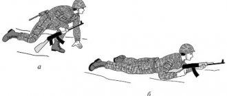
Incomplete disassembly and assembly of the Makarov "PM" pistol
1. Separate the magazine from the pistol by moving the magazine latch back. 2. Check that there is no cartridge in the chamber by moving the bolt housing back. 3. Pull the trigger guard down. 4. Separate the shutter housing from the frame by moving it back and lifting the rear end. 5. Remove the return spring from the barrel. The pistol is assembled in the reverse order.
Techniques for incomplete disassembly of the Makarov “PM” pistol: a
—
removing the magazine;
b -
pulling back the trigger guard;
c —
separation of the shutter from the frame.
Parts of the Makarov "PM" pistol with incomplete disassembly.
Techniques for assembling the Makarov “PM” pistol after incomplete disassembly: a - inserting the end of the return spring into the bolt channel; b
—
connecting the shutter to the frame;
c -
magazine insertion
Various variations and modifications
In the USSR, there were no sports or other versions based on the PM. The only attempt to modify the pistol were prototypes of weapons with a frame made of polymer materials. Such work was carried out at the very beginning of the 60s at the Instrument Design Bureau in the city of Tula. The results obtained during the tests did not satisfy the customer, and the experiments were not continued.
The situation changed dramatically at the very beginning of the 90s, when dozens of variants of Makarov sports, gas and air pistols chambered for cartridges of various calibers were produced on the basis of PM and PMM.
The most common was the IZH-70, designed for a standard cartridge and a .380ACP cartridge and equipped with an 8-round magazine.
It exists in several versions:
- IZH-70-17A and 18A, chambered for 380ASR and PM cartridges, respectively, with adjustable sight parts.
- IZH-70-17AS and 18AS, with chrome-plated outer surface.
- IZH-70-17AN and 18AN, commercial version of the pistol.
In addition to these options, multiple variations of the pistol were produced for the use of gas and traumatic cartridges. The most popular were 9 mm 6P42-9 and 7.6 mm 6P42-7.6. These variants are combat versions of weapons with a pin installed in the barrel, which does not allow the use of real cartridges.
Exactly the same design is the 6P42 (or IZH-79-8), developed for the use of 8 mm gas cartridges.
In the early 2000s, the IZH-79-9T (or a similar MP-79-9, which provided the ability to fire a rubber bullet using a special 9-mm RA gas cartridge) became popular. The ZID plant produced a pistol in a limited batch of several thousand pieces PM T.
All of these options were made on the basis of real weapons and were equipped with a partition in the barrel bore.
For official use, the MP-471 is used, developed for the use of a 10*23 mm traumatic cartridge and has been mass-produced since 2004.
A variant version is the MP-80-13T, which uses .45 Rubber cartridges as ammunition. The signal version of the pistol under the symbol MP-371, which is similar in appearance to the Makarych, deserves special mention. The ammunition used for it is “Zhevelo” or KV21 type capsules.
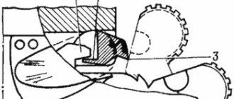
The mechanism for feeding cartridges into the chamber of the Makarov pistol "PM"
The cartridges are fed into the chamber by the lower part of the bolt, which is called the rammer. The supply for loading cartridges is provided by the magazine using a feeder and a feeder spring. This also includes the shutter lag. The magazine consists of a body, a feeder, a magazine cover, and a feeder spring. The magazine body is a box, the upper edges of the side walls of which are bent inward to hold the cartridges and feeder. At the bottom there are curved ribs for the lid, on the sides there are windows for control. The feeder has two bent ends to guide movement. One has a hook for engaging the slide stop. The feeder spring is a coiled spring of figured manufacture. One end of it serves to lock the lid. The magazine cover has hooks and a hole for a latch. The bolt stop has a protrusion for holding the bolt in the rear position, a button with a notch for the hand, a hole for connecting to the sear pins, a tooth for disabling the bolt stop with a magazine, and a reflector.
Return spring of the Makarov PM pistol.
Ejector with a bend and a spring for a Makarov pistol "PM": 1 - hook; 2
—
heel
Makarov pistol magazine "PM":
I - magazine body;
2 —
figured windows;
3 -
curved ribs;
4 — protrusion for magazine latch; 5 — oblique protrusion for turning off the shutter stop; 6 —
feeder;
-
hook for turning on the bolt stop;
8 —
magazine cover;
9 —
feeder spring.
Bolt stop of the Makarov "PM" pistol:
I - protrusion for holding the bolt;
2 —
button with a notch;
3 —
hole for connecting to the sear pins;
4 -
tooth for turning off the bolt stop with a magazine;
5 -
reflector.
Makarov pistol safety "PM": 1
—
a spring to hold the fuse in the required position;
2 —
hook for locking the trigger;
3 -
protrusion for blocking the trigger when the safety is turned on;
4 -
a ledge with a break for turning the sear and releasing the hammer when the safety is turned on.
Weight and size models
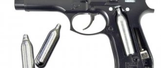
Based on the external appearance of the PM, there is a whole range of pneumatic and signal pistols, differing in caliber and workmanship. For example, Umarex produces a 6 mm version of the weapon under the designation Legends Makarov with gas supply from a cylinder. The air pistol quite accurately imitates its combat ancestor; it even has a delayed shutter setting mode. Two more pneumatic weapons with the appearance of a PM are widely known - these are the Gletcher PM and the Borner PM49. Both options are designed to use 4.5 mm steel balls as cartridges. The bolt parts of these pistols are fixed.
Simpler options are the 4.5 mm Baikal MP-654K in a standard black case and MP-654KS - with chrome-plated external parts. These variants are produced directly at the arms factory in Izhevsk. The pistols are equipped with clips for 13 steel balls with a diameter of 4.5 mm.
Pneumatic copies implement the principle of starting firing, like the combat version - either by pressing the trigger with great force or by cocking the hammer with your thumb. Early versions of the MP-654 were made on the basis of combat pistols, and differed only in some details.
With the tightening of legislation, the production of such variants was stopped, and all modern pistols are only an imitation of the external appearance of the PM. The shutter stop mode, called blowback in pneumatic weapons, is absent on them.
PM is an indispensable weapon in many computer games. For example, in the STALKER series of games it is the most common and accessible type of weapon.
For those who want to try themselves as a virtual shooter, there is a game that is a simulator of a Makarov pistol.
Setting the safety on the Makarov pistol "PM"
If there is no need to fire a shot, then the pistol is put on the safety cock as follows: either, without pulling the trigger, turn the safety flag; or the trigger is pulled manually. In the first case, without pulling the trigger, you should turn on the fuse by turning its flag all the way up so that the red recess is covered by the fuse flag. When the flag is turned, the following happens: the fuse protrusion lowers and, even before the sear begins to rise, stands in the way of the trigger movement; the ledge on the fuse axis with its shelf lifts the sear, it turns and releases the trigger; the trigger, under the action of the wide feather of the mainspring, turns and strikes the fuse protrusion; the safety catch, lowering, enters the hammer recess, locks and does not allow it to be cocked; The fuse rib, turning, extends beyond the left protrusion of the frame and blocks its movement. When the safety is on, the following occurs: the protrusion is lowered down and comes into contact with the front plane of the trigger; the shelf of the ledge on the axis, acting on the sear tooth, lifts it up and holds it in this position; the hook enters the hammer recess, rests against the protrusion and does not allow it to be cocked; the edge extends beyond the left protrusion of the frame and blocks the bolt with the frame. If the trigger is released not by the safety, but by manually pressing the trigger while holding the trigger, the latter, after releasing the trigger, also automatically becomes on the safety cock (“release” of the trigger).
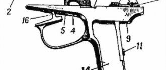
The position of the parts of the Makarov "PM" pistol before firing: 1 - firing pin; 2 - sear; 3 - shutter; 4 — ejector spring: 5 — ejector: b — barrel; 7 — return spring; 8 - store; 9 — trigger guard; 10 - frame; 11 — handle; 12 — mainspring; 13 — trigger rod; 14 — trigger; 15 - trigger; 16 — cocking lever.
Disadvantages of the model
One of the major disadvantages of the weapon is the high tendency of standard bullets to ricochet off any hard surface. This drawback was partly corrected by the creation of new types of cartridges for the Makarov pistol. Another disadvantage of the design is that the center of gravity of the PM is slightly shifted towards the barrel, which leads to fatigue in the shooter’s hand during prolonged firing.
But after 10-15 shots this drawback is not noticed.
The declared warranty life of the weapon does not exceed 5 thousand shots. However, there are many examples of pistols with rounds much greater than the warranty. At the same time, they remain in completely good condition. On the classic PM, the magazine capacity is insufficient; this flaw was partly eliminated on modernized versions of the pistol, but 12 rounds is not a good indicator for modern weapons.
Safety devices of the Makarov pistol "PM"
As mentioned above, protection from an accidental shot is carried out in three ways: “release” of the trigger - due to the wide feather of the mainspring; using a safety platoon; using a mechanical safety catch. The fuse is held in a given position by its spring and has a flag for switching from the “fire” position to the “safety” position and back; an axis with a ledge for turning the sear and releasing the hammer from cocking when switched to the “safety” position; a rib that ensures the closure of the shutter with the frame in the “safety” position; hook for locking the trigger in the “safety” position; a protrusion to absorb the impact of the trigger when the safety is turned on. As you can see, this small part is multifunctional in purpose and connections with other parts and is technologically complex.
Licensed versions
In addition to the USSR, the Makarov pistol was produced on the territory of member states of the Warsaw Pact. Such weapons, as a rule, were used to equip the armed forces of the country where they were produced. Since 1957, the Pistole M was officially produced on the territory of the GDR, which was an exact copy of the Soviet model.
There were attempts to create a variant chambered for 380ACP on its basis, but they were unable to move beyond the release of experimental samples. The tactical and technical characteristics of the German version of the Makarov pistol did not differ from the original model. After the reunification of Germany, the pistol remained in production, but only as a commercial version under the designation Pistole Simson-Suhl Makarov.
Bulgaria became the second major producer of licensed PM in Eastern Europe. Such pistols were called Makarov and were manufactured in land and naval versions.
Comparing PM and PMM<—/noindex—>
In 1990, the Arsenal R-M01 version appeared, which was distinguished by the ergonomics of the trigger guard and handle. These pistols were produced in sporting and civilian versions chambered for 380ACP and 9*18 cartridges, and could have chrome-plated external elements.
The B1300 was produced in small series, which had a shortened handle with a modified design of the linings.
The third manufacturer was China, which in 1959 launched mass production of an army pistol under the designation Type 59 and a training and sports version of the Norinco Sporting Pistol.
After the collapse of the USSR, Ukraine became a major supplier of various variants of Makarov-based pistols. At different periods of time, Ukrainian factories produced traumatic versions of the PMR (aka “Viy”), PM-T, PM-GT, PM-RF and “Berkut”.
All these designs are based on Makarov combat pistols, which, after Ukraine gained independence, remained stored in army warehouses in large quantities. A characteristic feature of all Ukrainian traumatic Makarovs is a safety plate welded into the barrel. Reverse conversion of such weapons into a combat version is impossible. All traumatic pistols are chambered for the 9 mm RA cartridge.
At the beginning of 2013, a small company began producing the PMF-1 pistol, converted to use the 4-mm Flaubert system cartridge. In such cartridges, only the primer is used as a propellant charge, which ensures its low power. The PMF-1 design has a drum magazine for 5 rounds, i.e. in fact, the pistol was turned into a revolver, the drum of which is located inside the body.
What weapons are most often remade?
What are the modifications of the MP-371?
Conventionally, they can be divided into 2 types: criminal and non-criminal.
The first is when a signal pistol is converted to fire traumatic or live ammunition.
The second is when the pistol, without acquiring damaging properties, receives some internal or external improvements.
If everything is clear with the first case, then with the second there are many nuances.
For example, the most common modification of the MP-371 is the introduction of automatic weapon reloading, when the owner implements the operation of the automation like a combat analogue. This eliminates the need to manually pull the bolt before each shot.
When fired, the pistol automatically removes the cartridge with the spent Zhevelo primer and, with the movement of the bolt forward, sends a new cartridge into the chamber. It is this alteration, which is also called the fashionable word “tuning,” that does not threaten the owner with absolutely anything, since the MP-371 has not lost its properties as a signal weapon and has not acquired the destructive properties of a firearm, remaining the same MP-371 according to the certificate.
Since, in accordance with the Federal Law “On Weapons”, the basis for the circulation of civilian weapons on the territory of the Russian Federation is a certificate, only in the case described above will the converted product comply with it. All other cases that we describe below will already be outside the scope of the certificate and, as a result, converted pistols will be confiscated by law enforcement agencies as having no grounds for circulation.
Well, responsibility for storing or manufacturing these modifications will be determined based on the properties acquired by the former MP-371 signal pistol. The second most popular modification is changing the MP-471 caliber for the 10TK or 10*24 light-noise cartridge, which are used in cooled weapons. This is understandable: the reluctance to pay at least 4 times more for a cooled weapon encourages the owner of a signal pistol to get a louder and more realistic model for a cooled cartridge. The alteration work itself is not complicated and not particularly expensive. At the same time, the owner is driven by the idea that he is not making the pistol a combat weapon.
Yes it is. However, if such a pistol is found in the owner’s possession in the absence of a passport and a certificate for the weapon, it will be sent for examination, which will establish that this product is an MP-371 signal pistol handcrafted for the light-sound cartridge. If it is structurally impossible to fire any projectile equipment from a converted pistol, then Articles 222 and 223 of the Criminal Code of the Russian Federation will be avoided, but you will still have to bear responsibility under several articles of the Code of Administrative Offenses of the Russian Federation. As well as paying a fine equal to approximately two of the most expensive models of cold PM on the market.