Chapter III PURPOSE AND CONSTRUCTION OF PISTOL PARTS AND MECHANISMS, CARTRIDGES AND ACCESSORIES
Chapter III
PURPOSE AND CONSTRUCTION OF PISTOL PARTS AND MECHANISMS, CARTRIDGES AND ACCESSORIES
Purpose and structure of pistol parts and mechanisms
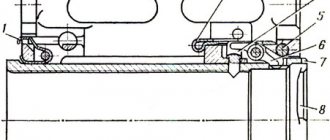
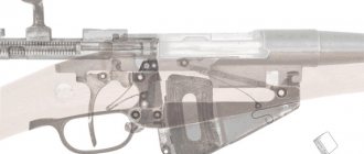
23. Frame with barrel and trigger guard (Fig. 25).
The barrel serves to direct the flight of the bullet. The inside of the barrel has a channel with four rifling, winding from left to right. The rifling serves to impart rotational movement to the bullet. The spaces between the cuts are called margins. The distance between two opposite fields (in diameter) determines the caliber of the bore; it is equal to 9 mm. From the breech, the bore is smooth and of larger diameter; it serves to house the cartridge and is called the chamber. The chamber has a ledge.
A
b
Rice. 25. Frame with barrel and trigger guard:
A
- left-hand side;
b
- right side;
1
— base of the handle;
2
- trunk;
3
— stand for attaching the barrel;
4
— window for placing the trigger and the ridge of the trigger guard;
5
- trunnion sockets for trigger trunnions;
6
— curved groove for placement and movement of the front axle of the trigger rod;
7
— trunnion sockets for the trigger and sear trunnions;
8
— grooves for directing the movement of the shutter;
9
— window for mainspring feathers;
10
— cutout for the bolt stop;
11
— boss with a threaded hole for fastening the handle with a screw and the mainspring with a bolt;
12
— cutout for magazine latch;
13
— boss with a socket for attaching the trigger guard;
14
— side windows;
15
— trigger guard;
16
- ridge to limit the movement of the shutter back;
17
- window for exiting the upper part of the store
On the breech of the barrel there is a boss for attaching the barrel to the frame stand and a hole for the barrel pin. There is a bevel on the boss and at the bottom of the chamber to guide the cartridge from the magazine into the chamber.
The outer surface of the trunk is smooth. A return spring is placed on the barrel.
The barrel is connected to the frame with a press fit and secured with a pin.
The frame serves to connect all parts of the gun. The frame with the base of the handle is one piece;
In the front part of the frame there is: on top - a stand for attaching the barrel, on the bottom - a window for placing the trigger and the ridge of the trigger guard. On the side walls of this window there are trunnion sockets for the trigger trunnions. The frame stand has: in the upper part there is a hole in which the barrel is fixed; below is a window for placing the trigger head; on the right is a curved groove for the placement and movement of the front axle of the trigger rod.
In the rear part, the frame has: on top - protrusions with trunnion sockets for the trigger and sear trunnions and with grooves for directing the movement of the shutter (trunnion sockets for the trigger trunnions and the right trunnion socket for the sear trunnion have slots); below is a window for the mainspring feathers.
In the middle part of the frame there is a window for the exit of the upper part of the magazine and a cutout on the left wall for the bolt stop.
Note
. Some pistols have holes drilled into the frame to reduce weight.
The base of the handle is used to attach the handle, the mainspring and to house the magazine. It has side windows (right and left) to reduce the weight of the pistol; lower window for inserting a magazine; on the rear wall there is a boss with a threaded hole for attaching the mainspring using a bolt and a handle using a screw; at the bottom there is a cutout for the magazine latch; in the front wall there is a boss with a socket for attaching the trigger guard to the frame using an axis.
The trigger guard serves to protect the tail of the trigger from accidentally pressing it. It has a ridge (tide) at the front end to limit the shutter stroke when moving backwards. The trigger guard is held in the frame in the upper position by a spring and a bend located in a socket on the front wall of the base of the handle.
24. The bolt (Fig. 26) serves to feed a cartridge from the magazine into the chamber, lock the barrel bore when firing, hold the cartridge case (remove the cartridge) and cock the hammer.
On the outside the bolt has: a front sight for aiming; transverse groove for rear sight; a notch between the front sight and the rear sight to prevent the surface of the bolt from reflecting when aiming; on the right side there is a window for ejecting the cartridge case; ejector groove; socket for a bender with an ejector spring; on the left side there is a socket for the fuse and two recesses for the fuse lock: the upper one for the “safety” flag position and the lower one for the “fire” flag position, next to the upper recess there is a red circle that opens when the flag is set to the “fire” position and closes with a flag when the fuse is turned on; on both sides there is a notch for ease of retracting the shutter by hand; at the rear end of the bolt there is a groove for the trigger to pass through.
A
b
Rice. 26. Shutter:
A
- left-hand side;
b
- bottom view;
1 - front sight; 2
- rear sight;
3
— window for ejecting the cartridge case;
4
- fuse socket;
5
- notch;
6
— channel for placing a barrel with a return spring;
7
- longitudinal projections to guide the movement of the shutter along the frame;
8
— tooth for setting the bolt to the bolt stop;
9
— groove for the reflector;
10
— groove for the release protrusion of the cocking lever;
11
— recess for disconnecting the sear from the cocking lever;
12
- rammer;
13
— protrusion for separating the cocking lever from the sear;
14
— recess for placing the release protrusion of the cocking lever;
15
— groove for the trigger;
16
- comb
Inside the bolt has: a channel for placing the barrel with a return spring; longitudinal projections to guide the movement of the shutter along the frame; tooth for setting the bolt to the bolt stop; crest; groove for reflector; groove for the release protrusion of the cocking lever; a cup for placing the bottom of the sleeve; rammer for sending a cartridge from the magazine to the chamber; protrusion for separating the cocking lever from the sear; a recess for placing the release protrusion of the cocking lever when the trigger is pressed; on the right side of the bolt ridge there is a recess designed to disconnect the sear from the cocking lever when removing the bolt from the bolt stop with the trigger pressed; channel for placing the striker.
The firing pin (Fig. 27) serves to break the primer. It has: in the front part there is a firing pin, in the rear part there is a cut for the fuse, which holds the firing pin in the bolt channel.
Rice. 27.
Drummer:
1
— striker;
2
- cut for fuse
The striker is made triangular in order to reduce its weight and reduce friction surfaces.
The ejector (Fig. 28) serves to hold the cartridge case (cartridge) in the bolt cup until it meets the reflector. It has a hook that slides into the annular groove of the sleeve and holds the sleeve (cartridge) in the bolt cup, and a heel for connecting to the bolt; At the rear of the ejector heel there is a ledge for placing the compression head. In the rear part of the ejector there is a recess for convenient recessing of the bend with a rubbing lip when separating the ejector from the bolt. The ejector is inserted into a groove in the bolt.
Rice. 28.
Ejector:
1
- hook;
2
— heel for connecting to the bolt;
3
- oppression;
4
— ejector spring
The oppression in the head part is thickened. The front end of the ejector spring, which is put on the rear part of the bend (smaller diameter), rests against the thickened part.
The pulley with the ejector spring is inserted into the socket in the bolt. Under the action of the spring, the ejector hook is always inclined towards the bolt cup.
The fuse (Fig. 29) serves to ensure safe handling of the pistol. It has: a flag for moving the safety from the “fire” position to the “safety” position and back; a latch for holding the fuse in its assigned position; an axis on which a ledge with a shelf is made to rotate the sear and release the hammer from cocking when the safety is moved to the “safety” position; a rib for locking the bolt with the frame when the safety is set to the “safety” position; hook for locking the trigger in the “safety” position; a protrusion to absorb the impact of the trigger when the safety is engaged.
Rice. 29.
Fuse:
1
— fuse box;
2
— clamp;
3 - ledge; 4
- rib;
5
— hook;
6
- protrusion
The fuse is inserted into the shutter socket.
The rear sight together with the front sight serves for aiming. With its base it is inserted into the transverse groove of the shutter.
25. The return spring (Fig. 30) serves to return the bolt to the forward position after firing. The outermost coil of one end of the spring has a smaller diameter compared to the other coils. With this coil, the spring is put on the barrel during assembly to ensure that it is securely held on the barrel when disassembling the pistol. The spring, put on the barrel, is placed with it in the bolt channel.
Rice. thirty.
Return spring
26. The trigger mechanism (Fig. 31) consists of a trigger, a sear with a spring, a trigger rod with a cocking lever, a trigger, a mainspring and a mainspring slide.
Rice. 31.
Trigger parts:
1
- trigger;
2
— sear with a spring;
3
— trigger rod with cocking lever;
4
— mainspring;
5
— trigger;
6
— mainspring valve
The trigger (Fig. 32) is used to strike the firing pin. It has on top a head with a notch for cocking the hammer by hand; on the front plane there is a cutout to ensure free movement of the trigger when it is decocked; recess for catching the fuse; at the base of the trigger there are two ledges: the upper one is a safety cocking, the lower one is a combat cocking; on the sides there are trunnions on which the trigger rotates in the trunnion sockets of the frame. and arched grooves to reduce weight; on the right is a self-cocking tooth for cocking the hammer using the cocking lever; on the left is a protrusion for locking the trigger with a safety lock; below there is a recess for the wide feather of the mainspring; on the right, in the lower part of the base of the trigger, there is an annular recess for placing the heel of the cocking lever.
Rice. 32.
Trigger:
A
- left-hand side;
b
- right side;
1
— head with a notch;
2
- cutout;
3
- recess;
4
— safety platoon;
5
- combat platoon;
6
- trunnions;
7
— self-cocking tooth;
8
- protrusion;
9
— recess;
10
- annular recess
The trigger pins have flats for free separation of the trigger from the frame.
The sear (Fig. 33) serves to hold the hammer in combat and safety cock. It has: a spout for engaging the trigger ledges; axles on which the sear rotates in the axle sockets of the frame; on the left - a tooth for lifting the sear with the shelf of the fuse ledge when the fuse is moved to the “safety” position; on the right is a protrusion on which the cocking lever acts when the trigger is pulled.
There is a spring on the left sear pin. The connection between the sear spring and the sear is made detachable - the end of the spring fits into a special hole in the sear stand. The free end of the spring is bent in the form of a hook for connection with the bolt stop. The spring presses the nose of the sear to the trigger. The sear journals have flats for free separation of the sear from the frame.
Rice. 33.
Sear:
1
— the trunnions whispered;
2
- tooth;
3
- protrusion;
4
- whisper spout;
5
- sear spring;
6
- rack
The trigger rod with the cocking lever (Fig. 34) is used to release the hammer from cocking and cock the hammer when pressing the tail of the trigger.
Rice. 34.
Trigger rod with cocking lever:
1
- trigger pull;
2
— cocking lever;
3
— trigger rod pins;
4
— release protrusion of the cocking lever;
5
- cutout;
6
— self-cocking protrusion;
7
— cocking lever heel
The trigger rod has pins at the ends. The front pin connects to the trigger, and the rear pin connects to the cocking lever.
The cocking lever has: a release protrusion, with the help of which it disengages from the sear when the bolt moves backward; cutout for sear protrusion; self-cocking protrusion, which cocks the hammer when you press the tail of the trigger; the heel on which the narrow feather of the mainspring rests. The heel of the cocking lever is placed in the annular recess of the trigger.
Rice. 35.
Trigger:
1
— axle;
2
- hole;
3
- tail
The trigger (Fig. 35) is used to release the hammer from combat cocking and cock the hammer when firing by self-cocking. It has: trunnions that fit into the trunnion sockets of the frame; a hole for connecting to the trigger rod and a tail.
The trigger head is inserted into the window of the frame stand.
The mainspring (Fig. 36) serves to actuate the hammer, cocking lever and trigger rod; it has: a wide feather for acting on the trigger; a narrow feather for acting on the cocking lever and trigger rod; in the middle part there is a hole for a spring for a tide with a threaded hole in the base of the handle. The lower end of the mainspring is the magazine latch. The end of the wide feather of the mainspring is curved to ensure “release” of the hammer, i.e., to put the hammer on the safety cock in the lowered position. The mainspring is attached to the base of the handle with a bolt.
Rice. 36.
Action spring:
1
- wide feather;
2
- narrow feather;
3
- bumper end;
4
- hole;
5
- latch
Rice. 37.
Handle with screw:
1
- swivel;
2
- grooves;
3
- hole;
4
- screw
27. The handle with a screw (Fig. 37) covers the side windows and the rear wall of the base of the handle and serves to make it easier to hold the pistol in your hand. It has: a hole for the screw that secures the handle to the base of the handle; swivel for attaching a pistol strap; grooves for freely sliding the handle onto the base of the handle; in the rear wall there is a recess for the magazine latch. In the hole for the screw there is a metal sleeve, which is designed to stop the screw head from being unscrewed arbitrarily. The handle is made of plastic.
The handle screw is used to secure the handle and latch to the base of the handle. It has a head and a threaded part.
28. The bolt stop (Fig. 38) holds the bolt in the rear position after all the cartridges from the magazine have been used up. It has: in the front part - a protrusion for holding the shutter in the rear position; a knurled button to release the shutter by pressing your hand; in the rear part there is a hole for connecting to the left sear pin; in the upper part there is a reflector for reflecting cartridge cases (cartridges) outward through the window in the bolt.
Rice. 38.
Shutter lag:
1
- protrusion;
2
— button with a notch;
3
- hole;
4
- reflector
The front part of the slide stop is inserted into a cutout in the left wall of the frame.
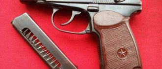
29. The magazine (Fig. 39) holds eight rounds. It consists of a body, a feeder, a feeder spring and a cover.
The magazine body (Fig. 40) connects all parts of the magazine. The upper edges of the side walls of the case are bent inward to hold the cartridges and feeder, as well as to guide the cartridges as they are fed into the chamber by the bolt. It has: windows in the side walls to reduce the weight of the magazine and to determine the number of cartridges in the magazine; at the bottom there are curved ribs for the magazine cover, a protrusion for the magazine latch, a cutout for free passage of the left wall of the magazine cover, a groove for the passage of the feeder tooth.
Rice. 39.
Shop:
1
- store body;
2
— feeder;
3
— feeder spring;
4
— magazine cover
The magazine is inserted into the base of the handle through the lower window.
Rice. 40.
Store body:
1
- window;
2
- curved rib;
3
- protrusion;
4
- cutout;
5
- gutter
Rice. 41.
Feeder:
1
- bent ends;
2
- tooth
The feeder (Fig. 41) is used to feed cartridges. It has two bent ends that direct its movement in the magazine body. On one of the bent ends of the feeder on the left side there is a tooth for turning on the bolt stop when all the cartridges from the magazine are used up.
The feeder spring (Fig. 42) is used to feed the feeder with cartridges upward when firing. The lower end of the spring is bent to lock the magazine cover.
Rice. 42.
Feeder spring
The magazine cover (Fig. 43) has a hole for the bent (lower) end of the feed spring and grooves with which it fits onto the curved ribs of the magazine body.
Rice. 43.
Magazine cover:
1
- hole;
2
- grooves
Purpose and device of the pistol accessory
30. Pistol accessories include (Fig. 44): holster, wiper, spare magazine, pistol strap.
The holster is used to carry and store the pistol, spare magazine and cleaning. The holster consists of a body, a cover, a spare magazine pocket, front and rear carry loops, a clasp, cleaning loops and an internal accessory strap.
The wiper is used to disassemble, reassemble, clean and lubricate the gun. The rubbing has: at one end - a protrusion for removing and installing the hook of the sear spring and for recessing the oppression when separating the ejector; a slot for threading tow or rags into it; on the other there is a ring to hold the wipe while cleaning. At the junction of the ring there is a blade for tightening and screwing in the handle screw when disassembling and assembling the pistol.
Rice. 44.
Gun accessory:
A
— holster:
1
— body;
2
- cover;
3
— pocket for a spare magazine;
4
- front wear loop;
5
- rear wear loop;
6
— fastener;
7
— loops for wiping;
8
— internal auxiliary strap;
b
- spare magazine;
c
- rubbing:
1
- blade;
2
— wiping slot;
3
- protrusion;
g
- pistol strap:
1
- belt;
2
— carabiner;
3
- loop
The pistol strap secures the pistol to the waist (trouser) belt. It consists of a belt, a carabiner and a loop for a waist (trouser) belt.
Chuck device
31. A 9-mm pistol cartridge (Fig. 45) consists of a cartridge case, a primer, a powder charge, and a bullet.
The sleeve serves to place the powder charge and connect all parts of the cartridge; during a shot, it prevents the breakthrough of gases from the barrel bore through the chamber.
Rice. 46.
General view of the 9 mm pistol cartridge and its design:
1
- sleeve;
2
— capsule;
3
- powder charge;
4
- bullet;
5
- bimetallic (clad) shell;
6
- steel core;
7
- lead shirt
At the bottom of the sleeve there are: a slot for a primer; an anvil on which the primer is struck; two seed holes through which flames from the percussion composition of the primer penetrate to the powder charge. Outside, at the bottom of the sleeve, there is an annular groove for hooking the ejector.
The charge consists of smokeless pyroxylin powder.
The capsule serves to ignite the powder charge. It consists of a brass cap with impact compound pressed into it and a foil circle covering the impact compound. When the striker strikes, the impact composition ignites.
The bullet consists of a bimetallic (clad) shell into which a steel core is pressed. There is a lead jacket between the bullet and the steel core.
32. Cartridges for loading the pistol are loaded into an 8-round magazine. The magazine is loaded by inserting and retracting the cartridges by hand.
33. The cartridges are sealed in standard wooden cartridge boxes of 2560 pcs. in everyone. Each box contains two rolled-up iron or sealed galvanized boxes, in which cartridges are placed in cardboard packs, 16 cartridges per pack. One iron box holds 80 cardboard packs.
On the side walls of the wooden boxes there are inscriptions indicating the nomenclature of the cartridges placed in these boxes: the batch number of the cartridges, the month and year of manufacture of the cartridges and gunpowder, the manufacturing plant, the brand and batch of gunpowder, the number of cartridges in the box.
The weight of one box of cartridges is about 33 kg.
History of creation
The creation of a new version of the weapon began shortly after the end of the Great Patriotic War, which showed the shortcomings of the TT pistol and Nagan revolver, which were in service with the Red Army. The condition of the competition, held in 1947-48, was the creation of a pistol with a design similar to the German Walter PP of the 1929 model.
Initially, two calibers were provided for the weapon - 7.65 and 9 mm, but the first was quickly abandoned. For the 9 mm caliber, a domestic PM cartridge with a size of 9*18 was developed, which was slightly larger and more powerful than the “Walter” original.
The main advantages of such a cartridge were a greater stopping effect (compared to 7.62*25 from the TT) and the possibility of using a simplified automatic circuit with a fixed barrel and a freely moving bolt in the Makarov pistol.
The designs of many gunsmith designers were entered into the competition, among whom were the famous names F.V. Tokareva, S.A. Korovina, S.G. Simonov and many others. N.F. also presented his project. Fedorov.
Pistols, Mauser, Beretta and a number of others acted as opponents to these designs.
According to all test results, the best performance was found in the design of the Makarov pistol of 9 mm caliber, which was recommended for mass production, as well as for adoption under the designation PM. The designer managed to perfectly calculate the relative position of the cartridge relative to the chamber and the optimal geometry of the mating parts.
Thanks to this, it was possible to completely avoid the problem of jamming in the inclined part of the chamber. Since 1951, supplies of 9 mm PM began for the needs of the army and police. Thus began the gradual displacement of TT pistols.
Specifications
The main purpose of the 9 mm Makarov pistol is to be used as a personal weapon for attack and defense at short distances.
A technically sound 9mm PM in the hands of a good shooter shows excellent fire accuracy. At a distance of 50 meters, all bullets fall into a circle with a diameter of 320 mm, while at a distance of 20 meters this diameter drops to 130 mm.
The standard PM cartridge has a bullet with a steel core encased in a lead jacket.
Because of this design, the bullet is unable to penetrate steel plates and often ricochets when hitting hard surfaces.
They tried to correct this deficiency by creating new types of bullets and cartridges, some of which reached mass production. At the same time, the destructive power of a standard bullet is maintained at a distance of up to 350 meters.
One of these developments was a special armor-piercing cartridge 9*18 PBM (index 7N25). The bullet design uses a carbide core covered with an aluminum aerodynamic shell. Due to this, it was possible to reduce the weight of the bullet to 3.7 grams, which allows a standard powder charge to accelerate it to a speed of 519 m/sec.
The recoil parameters remained virtually unchanged.
Such a bullet penetrates a 5 mm sheet of ordinary carbon steel grade ST3 or a 2.4 mm sheet of armor steel from 10 meters. At distances of up to 30 meters, through penetration of the 6B5-12 body armor is ensured, while the bullet can continue further movement.
| Parameter | Meaning |
| Empty weight | 730 grams |
| Loaded weapon weight | 810 grams |
| Barrel length | 93.5 mm |
| Number of rifling | 4, directed upwards to the right |
| Rate of fire | Up to 30 rounds/min |
| Aiming distance | Up to 50 meters |
| Initial speed of a standard bullet | Not lower than 315 m/sec |