contents .. 1 2 3 ..
Chapter III
PURPOSE, CONSTRUCTION OF PARTS AND MECHANISMS OF THE KALASHNIKOV AUTOMATIC (Machine Gun), ACCESSORIES AND CARTRIDGES
Purpose, arrangement of parts and mechanisms of the Kalashnikov assault rifle (machine gun)
11. Barrel
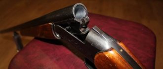
(Fig. 27) serves to direct the flight of the bullet. The inside of the barrel has a channel with four rifling, winding from left to right. The rifling serves to impart rotational motion to the bullet. The spaces between the cuts are called margins. The distance between two opposite fields (in diameter) is called the bore caliber; for an assault rifle (machine gun) it is 5.45 mm. In the breech, the channel is smooth and shaped like a cartridge case; this part of the channel serves to accommodate the cartridge and is called the chamber. The transition from the chamber to the rifled part of the bore is called the bullet entrance.
On the outside, the barrel has a front sight base for a machine gun with a thread (for a machine gun there is a thread on the muzzle) for screwing on a muzzle brake-compensator for a machine gun (for a machine gun - flame arrester) and
Rice. 27. Barrel:
a - external view of the machine gun barrel; b - external view of the machine gun barrel; c - sectional view of the breech; g - trunk section; 1 - threaded part; 2 — bullet entrance; 3 — chamber; 4 — base of the front sight; 5 - gas chamber; 6 - coupling; 7 — sight block; 8 — recess for the barrel pin; 9 - thread; 10 — bipod base; 11 - eye ring
Rice. 28. Muzzle brake-compensator and flash suppressor: a - muzzle brake-compensator; b - flame arrester; 1 - corolla; 2 - windows; 3 - gap; 4 - compensation holes; 5 — recess for the retainer; 6 - bevel; 7 - internal thread
Rice. 29. Front sight base:
a - automatic machine; b - machine gun; 1 — stop with a recess for a cleaning rod; 2 - support for a bayonet-knife with a hole for a cleaning rod; 3 — skid with front sight; 4 — front sight fuse; 5 — clamp; 6 — thread for screwing on the muzzle brake-compensator (flash arrester)
| bushings for firing blank cartridges, a gas outlet, a gas chamber, a connecting coupling, a sight block and a cutout on the breech end for the ejector hook. The front sight base, gas chamber and sight block are secured to the barrel using pins. The machine gun, in addition, on the front of the barrel has a bipod base for attaching the bipod to the barrel with a hole for a cleaning rod and a ring with an eye to increase the reliability of fastening the cleaning rod. Muzzle brake-compensator of the machine gun (Fig. 28) serves to increase the accuracy of combat and reduce recoil energy. It has two chambers: front and rear (with a round hole in them for the bullet to escape). The front chamber has a rim on which the ring of the bayonet-knife is put on when it is attached to the machine gun, a rectangular groove into which the protrusion of the bayonet-knife fits, and two windows for the exit of powder gases. The rear chamber has two slits in front, and in the middle part there are three compensation holes for the exit of powder gases. At the rear, the muzzle brake-compensator has an internal thread for screwing onto the base of the front sight, a recess into which the lock and a circular bevel fit, making it easier to insert and remove the cleaning rod. Machine gun flash suppressor serves to reduce the size of the flame when fired. It has a thread for screwing onto the barrel, five recesses for the lock and five longitudinal slots for the release of gases. Front sight base (Fig. 29) has a stop with a recess for a ramrod, a hole for a front sight slide, a front sight safety device and a retainer with a spring. The clamp keeps the muzzle brake-compensator (flash suppressor) and the bushing for firing blank cartridges from screwing together. The machine gun, in addition, on the base of the front sight has a stop for attaching a bayonet-knife with a hole for a ramrod. Gas chamber serves to direct powder gases from the barrel to the gas piston of the bolt frame. It has a gas outlet, a pipe with a channel for the gas piston and holes for the exit of powder gases. Coupling serves to attach the fore-end to the machine gun (machine gun). It has a fore-end lock, a sling swivel and a hole for a cleaning rod. The barrel is connected to the receiver by means of a pin and cannot be separated from it. 12. Receiver (Fig. 30) serves for |
| Rice. 30. Receiver: 1 - cutouts; 2 - reflective protrusion; 3 — bends; 4 — guide protrusion; 5 - jumper; 6 - longitudinal groove; 7 - transverse groove; 8 — magazine latch; 9 — trigger guard; 10 — pistol grip; 11 - butt | connecting the parts and mechanisms of an assault rifle (machine gun) to ensure that the barrel bore is closed by the bolt and the bolt is locked. The trigger mechanism is placed in the receiver. The top of the box is closed with a lid. The receiver has: · inside there are cutouts for locking the bolt, the rear walls of which are lugs; bends and guide protrusions for directing the movement of the bolt frame and bolt; reflective protrusion for reflecting cartridges; jumper for fastening the side walls; a protrusion for hooking the magazine and one oval protrusion on the side walls for guiding the magazine; |
· at the top rear there are grooves: longitudinal - for the heel of the guide rod of the return mechanism and transverse - for the receiver cover; tail with a hole for attaching the butt to the receiver;
· in the side walls there are four holes, three of them for the axes of the trigger mechanism, and the fourth for the translator trunnions; on the right wall there are two fixing recesses for placing the translator on automatic (AB) and single (OD) fire;
· below - a window for the magazine and a window for the trigger.
An assault rifle with a folding stock also has holes for the stock retainer and latch (Fig. 33).
| Rice. 31. Sight: a - machine gun; b - machine gun; 1 — sight block; 2 - sector; 3 — sighting bar; 4 - clamp; 5 — mane of the sighting bar; 6 — clamp latch; 7 — rear sight screw handwheel; 8 - rear sight | For a machine gun with a folding butt, the receiver at the rear has a slot for the left latch with a spring that holds the butt in the folded position; on the right wall there is a cutout for the right latch of the butt and a hole for pressing on the right latch when recessing it; on the left wall there is an eye for attaching the butt and a hole for the front end of the left latch (Fig. 34 and 35). Attached to the receiver are: a butt with a swivel, a pistol grip and a trigger guard with a magazine latch. For machine guns (machine guns) with night sights, a bar for attaching a night sight is attached to the left side wall. 13. Sighting device serves for aiming an assault rifle (machine gun) when firing at targets at various ranges. It consists of a sight and a front sight. Aim (Fig. 31) consists of a sight block, a leaf spring, an aiming bar and a clamp. Sight block has two sectors to give the aiming bar a certain height, eyes for attaching the aiming bar, holes for the pin and gas tube lock; inside there is a socket for a leaf spring and a cavity for the bolt frame; on the back wall there is a semicircular cutout for the receiver cover. |
The sight block is placed on the barrel and secured with a pin.
Leaf spring
is placed in the socket of the sight block and holds the aiming bar in its given position.
Sighting bar
has a mane with a slot for aiming and cutouts for holding the clamp in the installed position by means of a latch with a spring. On the sighting bar (on the top of the machine gun, on the top and bottom of the machine gun) there is a scale with divisions from 1 to 10; The scale numbers indicate firing ranges in hundreds of meters.
In addition, the machine gun has the letter “P” on the sighting bar - a permanent sight setting, approximately corresponding to sight 4 (firing range 440 m).
On a machine gun, the sighting bar has a socket for the rear sight and risk; on the wall of the rear sight socket there is a scale with ten divisions; each of which corresponds to two thousandths of the firing range.
Rear sight
the machine gun has a mane with a slot for aiming, a screw with a handwheel, a spring, a washer and a pin.
Clamp
placed on the sighting bar and held in position by a latch. The latch has a tooth, which, under the action of a spring, slides into the cutout of the sighting bar.
Front sight
screwed into the skid, which is fixed to the base of the front sight. On the slide and on the base of the front sight there are marks that determine the position of the front sight.
The machine gun (machine gun) is supplied with a device for firing at night and in conditions of limited visibility
(self-luminous attachments). It consists of a folding rear sight with a wide slot, mounted on the mane of the sighting bar, and a wide front sight, placed on top of the front sight of the weapon. Self-luminous dots are applied to the rear sight and front sight of the device.
The new type of device has self-luminous stripes: two horizontally located on the rear sight and one vertically on the front sight.
The device for shooting at night is installed on the machine gun (machine gun) and is verified when it enters the troops and is not separated from it during operation.
The combat of a weapon when shooting with a device remains basically the same as with an open sight. In the event of a significant deviation in height from the average point of impact, it is necessary to secure the weapon in the sighting machine, aim at the target and select the rear sight so that the aiming line with the open sight and the device coincide.
When shooting during the day, the rear sight and front sight of the device fold down. In this position, they do not interfere with the use of the sighting device of the machine gun.
When shooting at night and in conditions of limited visibility, the rear sight of the device is rotated upward until it comes into contact with the mane of the sighting bar, and the front sight of the device is moved up along the spring and put on the front sight.
| Rice. 32. Receiver cover: 1 - stepped cutout; 2 - hole; 3 — stiffeners | 14. Receiver cover (Fig. 32) protects parts and mechanisms placed in the receiver from contamination. On the right side it has a stepped cutout for the passage of cartridges thrown out and for the movement of the bolt frame handle; at the back there is a hole for the protrusion of the guide rod of the return mechanism. The cover is held on the receiver using a semicircular cutout on the sight block, a transverse groove in the receiver and a protrusion of the recoil mechanism guide rod. |
15. Butt and pistol grip
serve for the convenience of operating a machine gun (machine gun) when shooting.
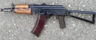
The permanent stock of the AK74, AK74N assault rifles (Fig. 33) and RPK74, RPK74N machine guns (Fig. 34) has a sling swivel for a belt, a socket for an accessory case and a butt plate with a cover over the socket. In the butt socket there is a spring for pushing out the pencil case. The permanent stock of an assault rifle can be wooden or plastic (for a machine gun it is wooden).
The folding stock of the AKS74 and AKS74N assault rifles consists of upper and lower rods, a butt plate, a clip and a tip, connected into one unit by welding. There is a sling swivel on the clip on the right side of the butt. In the folded position, the butt is held by a latch, and in the folded position - by a latch.
| Rice. 33. Butt and pistol grip of the machine gun: a - permanent (wooden) butt (sectional view); b - folding butt in the folded position; c — folding stock in the folded position; 1 — sling swivel; 2 — socket for a pencil case; 3 — butt plate; 4 - cover; 5 - spring for pushing out the accessory case; 6 — butt lock; 7 — butt latch; 8 — top link; 9 — lower link; 10 — clip; 11 — tip; 12 - axis; 13 — pistol grip; 14 — strap for attaching a night sight Rice. 35. Folding the butt of a machine gun: 1 - butt; 2 — receiver; 3 — pistol grip; 4 - hole in the receiver wall | Rice. 34. Butt and pistol grip of a machine gun: a - permanent butt (in section); b — folding stock (in folded position); 1 — sling swivel; 2 - socket for accessories; 3 — butt plate; 4 - cover; 5 - spring for pushing out the accessory case; 6 — protrusion of the butt with ears; 7 — receiver eye; 8 — right butt latch with a spring; 9 — back part of the left latch with a notch; 10 — latch spring; 11 — cutout for the right butt latch; 12 — pistol grip Rice. 36. Machine gun bipod: 1 — bipod base; 2 - legs; 3 - spring; 4 - protrusion; 5 — skid; 6 — spring fastener |
To fold the butt, you need to recess the latch (in this case, the latch will disengage with the tip of the butt) and turn the butt to the left around the axis until the butt is secured with a latch located on the left wall of the receiver.
To fold the butt, you need to move the latch back and turn the butt to the right until it is secured with a latch.
The folding butt of the RPKS74 and RPKS74N machine guns, in addition to that specified for the permanent butt of the machine gun, has a protrusion for the right latch of the butt, which holds the butt in the folded position, ears for attaching the butt to the receiver, and in the case of the RPKS74N, a recess where the bar for attaching a night sight when folding the butt is included.
To fold the butt, you need to push the right latch of the butt with a drift or a cartridge bullet through the hole in the right wall of the receiver (Fig. 35) and turn the butt to the left until it is secured with the left latch in the folded position.
To fold the butt, you need to press the rear part of the latch with a notch to the left with your finger and turn the butt to the right until it is secured with the right latch.
16.
The bipod of the machine gun
(Fig. 36) serves as a stop when firing. It has a base, two legs with runners for resting on the ground and protrusions for fixing the legs in the folded position, a spring for spreading the legs, a spring fastener on the left leg for fastening the legs in the folded position. The bipod is not separated from the machine gun.
17.
The bolt frame with a gas piston
(Fig. 37) serves to activate the bolt and trigger mechanism.
| Rice. 37. Bolt frame with gas piston: 1 - channel for the bolt; 2 - safety ledge; 3 — protrusion for lowering the self-timer lever; 4 — groove for bending the receiver; 5 — handle; 6 — figured cut; 7 – groove for the reflective protrusion; 8 - gas piston Rice. 38. Shutter: a ~ shutter core; b - drummer; c - ejector; 1 — cutout for the sleeve; 2-cutout for ejector; 3 - leading protrusion; 4 — hole for the ejector axis; 5 — combat ledge; 6 - longitudinal groove for the reflective protrusion; 7 - ejector spring; 8 ~ ejector axis; 9 — hairpin | The bolt frame has: inside there is a channel for the return mechanism, and a channel for the bolt; at the back there is a safety ledge; on the sides there are grooves for moving the bolt frame along the bends of the receiver; on the right side there is a protrusion for lowering (rotating) the self-timer lever and a handle for reloading the machine gun; at the bottom there is a shaped cutout to accommodate the leading protrusion of the bolt and a groove for the passage of the reflective protrusion of the receiver. A gas piston is mounted in front of the bolt frame. 18. Shutter (Fig. 38) serves to send the cartridge into the chamber, close the barrel bore, break the primer and remove the cartridge case (cartridge) from the chamber. It consists of a frame, a hammer, an ejector with a spring and an axis, and a pin. Shutter body has: on the front cut there is a cylindrical cutout for the bottom of the sleeve and a groove for the ejector; on the sides there are two lugs that, when the bolt is locked, fit into the cutouts of the receiver; on top there is a leading protrusion for turning the shutter when locking and unlocking; on the left side there is a longitudinal groove for the passage of the reflective protrusion of the receiver (the groove at the end is widened to ensure rotation of the bolt when locking); in the thickened part of the bolt frame there are holes for the ejector axis and pins. Inside the bolt frame there is a channel for placing the firing pin. |
Drummer
has a striker and a ledge for a hairpin.
Ejector
with a spring serves to remove the cartridge case from the chamber and hold it until it meets the reflective protrusion of the receiver. The ejector has a hook for gripping the cartridge case, a socket for the spring and a cutout for the axle.
Hairpin
serves to secure the firing pin and the ejector axis.
| Rice. 39. Return mechanism: 1 - return spring; 2 - guide rod; 3 - movable rod; 4 - coupling Rice. 40. Gas tube with receiver lining: 1 - gas tube; 2 — guide ribs for the gas piston; 3 - front coupling; 4 — receiver pad; 5 - rear coupling; 6 - protrusion; 7 - leaf spring Rice. 41. Parts of the trigger mechanism: a - trigger; b — mainspring; c - trigger; g - sear of a single fire; d — self-timer; e — self-timer spring; g - translator; z - axes; and - the spring whispered a single fire; k - trigger retarder; l — trigger retarder spring; m - tubular axis; 1 - combat platoon; 2 — self-timer cocking; 3 - curved ends; 4 - loop; 5 - figured protrusion; 6 — rectangular protrusions; 7 - tail; 8 - cutout; 9 - sear; 10 — lever; 11 - latch; 12 — front protrusion; 13 - sector; 14 - axle | 19. Return mechanism (Fig. 39). Serves to return the bolt frame with the bolt to the forward position. It consists of a return spring, a guide rod, a movable rod and a coupling. Guide rod has a stop for the spring at the rear end, a heel with projections for connection with the receiver and a protrusion for holding the receiver cover. Movable rod The front end has bends for putting on the coupling. 20. Gas tube with receiver lining (Fig. 40) consists of a gas tube, front and rear connecting couplings, a barrel lining, a metal half-ring and a leaf spring. Gas tube serves to direct the movement of the gas piston. It has guide ribs. The front end of the gas tube is put on the gas chamber pipe. Receiver pad serves to protect the hands of the machine gunner (machine gunner) from burns when shooting. It can be wooden or plastic for an assault rifle (for a machine gun it is wooden) and has a groove in which a metal half-ring is fixed, pressing the barrel lining away from the gas tube (this prevents the lining from swaying when the wood dries out). The barrel lining is mounted on the gas tube by means of front and rear connecting couplings; the rear coupling has a protrusion into which the gas tube contact rests; The leaf spring eliminates the longitudinal rolling of the tube. 21. Trigger mechanism (Fig. 41) is used to release the trigger from the combat cocking or from the self-timer cocking, striking the firing pin, ensuring automatic or single fire, stopping firing, preventing shots when the bolt is unlocked and putting the safety on the machine gun (machine gun). |
The trigger mechanism is placed in the receiver, where it is attached by three interchangeable axes, and consists of a trigger with
mainspring, hammer retarder with spring, trigger, single fire sear with spring, self-timer with spring, translator and tubular axis.
Trigger
with a mainspring used to strike the firing pin. The trigger has a combat cock, a self-timer cock, trunnions and a hole for the axle. The mainspring is put on the trigger pins and acts with its loop on the trigger, and with its ends on the rectangular protrusions of the trigger,
Trigger retarder[2]
serves to slow down the forward movement of the trigger in order to improve the accuracy of the battle when conducting automatic fire from stable positions. It has front and rear lugs, an axle hole, a spring and a latch.
Trigger
serves to keep the hammer cocked and to release the hammer. It has a shaped protrusion, an axle hole, rectangular protrusions and a tail. With its figured protrusion, it holds the trigger cocked.
Single fire sear
serves to hold the trigger in the rearmost position after firing, if the trigger was not released when firing a single fire. It is on the same axis with the trigger. The single-fire sear has a spring, a hole for the axis and a cutout into which the translator sector enters when conducting automatic fire and locks the sear. In addition, the cutout limits the forward rotation of the sector when the translator is put on safety.
Self-timer
serves to automatically release the trigger from cocking the self-timer when firing in bursts, as well as to prevent the trigger from being released when the barrel is open and the bolt is unlocked. It has a sear for holding the trigger while cocking the self-timer, a lever for turning the self-timer with the protrusion of the bolt frame when it approaches the forward position, and a spring.
The spring is located on the same axis as the self-timer. Its short end is connected to the self-timer, and its long end runs along the left wall of the receiver and fits into the annular grooves on the axes of the self-timer, hammer and trigger, keeping the axes from falling out.
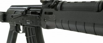
| Rice. 42. Forend (wooden): 1 — finger rest; 2 - protrusion; 3 - leaf spring; 4 - hole for cleaning rod Rice. 43. Store: 1 - body; 2 - cover; 3 — locking strip; 4 - spring; 5 — feeder; 6 - support protrusion; 7 - hook | Translator serves to set the machine gun (machine gun) to automatic or single fire, as well as to the safety catch. It has a sector with trunnions that fit into the holes in the walls of the receiver. The lower position of the translator corresponds to setting it to single fire (OD), the middle position to automatic fire (AB) and the top position to the safety. 22. Handguard (Fig. 42) serves for convenience of operation and to protect the hands of the machine gunner (machine gunner) from burns. It can be wooden or plastic for a machine gun (wooden for a machine gun). The forend is attached to the barrel from below using a coupling and to the receiver - through a protrusion that fits into the receiver socket. The body of the forend has a through hole for a cleaning rod. The rear of the forend has cutouts and a recess into which the leaf spring fits. The spring serves to prevent longitudinal pitching of the fore-end. Cutouts on the fore-end and receiver guard form windows for cooling the barrel and gas tube when firing. The plastic forend has a metal screen designed to reduce heating of the forend when firing. |
23. Shop
(Fig. 43) is used to place cartridges and feed them into the receiver. It consists of a plastic body, a cover, a locking bar, a spring and a feeder.
The magazine body connects all parts of the magazine; its side walls have bends on top (at the neck) to keep the cartridges from falling out and protrusions that limit the rise of the feeder; there is a hook on the front wall, and a support protrusion on the back wall, through which the magazine is attached to the receiver. On the rear wall of the case at the bottom there is a control hole to determine whether the magazine is fully loaded with cartridges.
The bottom of the case is closed with a lid. The cover has a hole for the protrusion of the locking bar.
Inside the housing there is a feeder and a spring with a locking bar. The feeder is held on the upper end of the spring by an internal bend on the right wall of the feeder; the feeder has a protrusion that provides a staggered arrangement of cartridges in the magazine. The locking bar is permanently fixed to the lower end of the spring and with its protrusion keeps the magazine cover from moving.
| Rice. 44. Bayonet: a - blade; b - handle; 1 - cutting edge; 2 - saw; 3 — sharpened edge; 4 - hole; 5 - belt; 6 - ring; 7 — belt hook; 8 — metal tip; 9 - connecting screw; 10 - longitudinal grooves; 11 - latch Rice. 45. Sheath: 1 — pendant with a loop fastener and a carabiner; 2 - plastic body; 3 – protrusion axis; 4 — emphasis; 5 — leaf spring clamp Rice. 46. Affiliation: 1 - ramrod; 2 - rubbing; 3 - brush; 4 - screwdriver; 5 — drift; 6 - pencil case; 7 - cover; 8 - oiler; 9 - clip; 10 - adapter | 24. Bayonet (Fig. 44) is attached to a machine gun to defeat the enemy in battle. On the blade there is a cutting edge, a saw, a sharpened edge, which in combination with the sheath is used as scissors, a hole into which the protrusion-axis of the sheath is inserted. Lever serves for ease of operation and for connecting the bayonet-knife to the machine gun. Sheath (Fig. 45) are used to carry a bayonet-knife on a waist belt. In addition, they are used in conjunction with a bayonet-knife for cutting wire. The scabbard has a suspension with a loop, a protrusion-axis, and a stop to limit the rotation of the bayonet-knife when acting like scissors; Inside the sheath there is a leaf spring with a lock to keep the bayonet-knife from falling out. Accessory to a machine gun (machine gun) 25. Belonging (Fig. 46) is used for disassembling, assembling, cleaning, lubricating the machine gun (machine gun) and quickly loading the magazine with cartridges. Accessories include: cleaning rod, cleaning rod, brush, screwdriver, drift, pencil case, oiler, clips and adapter. |
Ramrod
used for cleaning and lubricating the barrel bore, as well as channels and cavities of machine gun parts. It has a head with a hole for a punch and a thread for screwing on a wiper or brush.
Rubbing
used for cleaning and lubricating the barrel bore, channels and cavities of other parts of the machine gun. It has an internal thread for screwing onto a cleaning rod and a slot for rags or tow.
Ershik
used for cleaning the barrel bore with RFS solution.
Screwdriver and drift
used when disassembling and assembling an assault rifle (machine gun). The cutout at the end of the screwdriver is for screwing in and unscrewing the front sight, and the side cutout is for securing the wiper to the cleaning rod. For ease of use, the screwdriver is inserted into the side holes of the pencil case. When cleaning the barrel bore, a screwdriver is placed in the pencil case on top of the ramrod head.
Pencil case
serves for storing cleaning cloths, brushes, screwdrivers and drifts. It closes with a lid.
The pencil case is used as a handle for a screwdriver when screwing in and unscrewing the front sight and for turning the gas tube closure, as well as a handle for a cleaning rod.
The pencil case has through holes into which a ramrod is inserted when cleaning the machine gun, oval holes for a screwdriver and a rectangular hole for turning the gas tube lock when disassembling and assembling the machine gun.
Single neck oiler
serves to store lubricant; it is carried in the pocket of a shopping bag.
Clip
serves for carrying cartridges and quickly loading the magazine with cartridges. The clip holds 15 rounds. It has two longitudinal grooves and a leaf spring that keeps the cartridges from falling out. In addition, the leaf spring ensures a strong connection between the cage and the adapter.
Adapter
serves to connect the clip to the magazine when equipping it with cartridges. It has: at the bottom (widened part) two bends that fit into the corresponding grooves on the neck of the magazine; on top there are two longitudinal grooves for the holder, a hole for the holder spring and a stop that limits the advancement of the holder when inserting it into the adapter.
5.45mm live Kalashnikov cartridges
26.
A live cartridge (Fig. 47) consists of a bullet, a cartridge case, a powder charge and a primer.
| Rice. 47. Live cartridge: 1 - bullet; 2 - sleeve; 3 - powder charge; 4 — capsule; 5 - dulce; 6 — groove; 7 - anvil; 8 - seed hole; 9 - strike force | Rice. 48. Bullets: a - ordinary with a steel core; b - tracer: 1 - shell; 2 - steel core; 3 - lead jacket; 4 — core (lead); 5 - tracer composition |
27.
5.45 mm cartridges
are available with regular and tracer bullets. The head of the tracer bullet is painted green. To simulate shooting, blank (without a bullet) cartridges are used, which are fired using a special sleeve.
An ordinary
bullet
(Fig. 48, a) is designed to destroy enemy personnel located openly and behind barriers pierced by the bullet.
An ordinary bullet consists of a steel shell coated with tombac and a steel core. There is a lead jacket between the shell and the core.
Tracer bullet
(Fig. 48.6) is also designed to defeat enemy personnel. In addition, when a bullet flies in the air, its burning tracer composition leaves a luminous trace at firing ranges of up to 800 m, which allows for fire adjustment and target designation.
In the tracer bullet shell, a core is placed in the head part, and a block of pressed tracer composition is placed in the bottom part. During the shot, the flame from the powder charge ignites the tracer compound, which gives a luminous trail as the bullet flies.
28.
The sleeve
serves to connect all parts of the cartridge, protect the powder charge from external influences and eliminate the breakthrough of powder gases towards the bolt. It has a body for placing a powder charge, a barrel for securing a bullet and a bottom. On the outside, at the bottom of the sleeve, there is an annular groove for hooking the ejector. The bottom of the case has a primer socket, an anvil and two priming holes.
29. Powder charge
serves to impart forward motion to the bullet; it consists of spherical grained gunpowder.
30.
The capsule
serves to ignite the powder charge. It consists of a brass cap, a shock compound pressed into it, and a foil circle covering the impact compound.
31.
Capping of 5.45 mm cartridges is carried out in wooden boxes. Two hermetically sealed metal boxes of 1080 rounds each are placed in the box; cartridges in boxes are packed in cardboard packs of 30 pieces. In total, the box holds 2160 rounds.
There is a green stripe on the side walls of the boxes in which cartridges with tracer bullets are sealed. Each box contains a knife for opening the box.
contents .. 1 2 3 ..
Position of parts and mechanisms before loading
32. The bolt frame with a gas piston and bolt is in the extreme forward position under the action of the return mechanism, the gas piston is in the gas chamber pipe; The bore is closed by a bolt. The bolt is rotated around the longitudinal axis to the right, its lugs are located in the cutouts of the receiver - the bolt is locked. The return spring has the least compression.
The self-timer lever is rotated forward and downward under the action of the protrusion of the bolt frame (Fig. 49).
Rice. 49. The position of the trigger mechanism parts before loading with the safety on and the trigger pulled:
1 — trigger; 2 - translator sector; 3 — sear of a single fire; 4 — trigger retarder; 5 — figured protrusion of the trigger;
6 — mainspring; 7 - trigger; 8 — self-timer lever; 9 — bolt frame; 10 — self-timer sear
The trigger is released and rests against the bolt. The hammer is moved forward under the action of the trigger. The mainspring is at its lowest compression; with its loop it presses the trigger to the bolt, and with its curved ends it presses the rectangular protrusions of the trigger to the bottom of the receiver, while the tail of the trigger is in the forward position.
The trigger retarder, under the action of its spring, is pressed to the bottom of the receiver by its front protrusion.
The translator is in the uppermost position and closes the stepped cutout in the receiver cover (the translator is on safety); the translator's sector entered the cutout of the single-fire sear and is located above the right rectangular protrusion of the trigger (locks the trigger).