"Object 490". The USSR could create the most powerful tank in the world
The Hammer and Sickle
The Second World War clearly showed that in the field of tank building almost no one could compare with the USSR, including the gloomy genius of the Third Reich.
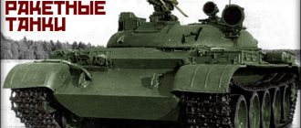
This status had to be maintained, and in addition, at a given hour X, the Soviet Army had to be ready to make a push to the English Channel. The USSR gave birth to such monsters as “Object 279”. Let us remember that it had a mass of 60 tons (a lot by the standards of the 50s) and, most interestingly, four tracks for better maneuverability. However, as we know, the development of the Soviet school of tank building was largely predetermined by relatively simple, not very expensive and quite powerful MBTs for their time, mainly the T-72 and T-64. Unfortunately, already in the 80s, their designs largely reached a dead end due to the difficulties of increasing crew protection in conditions of an extremely dense layout. This is how the now famous Object 477 “Hammer”, T-95 (aka “Object 195”) and many other developments appeared. The task was simple - to make the most survivable combat vehicle that would give the crew the opportunity to survive getting into the vitally dangerous spaces of the MBT. They didn’t forget about weapons: now the formidable promising 152 mm gun was considered as the main caliber instead of the usual 125 mm guns. This solution made it possible to dramatically increase firepower, but made the vehicle potentially heavier and also more difficult to maintain.
Only later, in Russia, the famous experimental “Black Eagle” will appear, which, in fact, became a very deep modernization of the T-80, but with fundamentally new crew protection capabilities and very good power density, surpassing even the best Western MBTs. We must assume that readers already know very well about “Armata”.
Two towers and four tracks
It would seem that there is nothing to surprise the sophisticated public with: many people remember both monstrous German projects and the Swedish “IKEA on tracks” in the person of Strv 103. As well as the above-mentioned failed successors of the 72nd. However, quite recently, the website btvt.info published materials about the absolutely amazing “Object 490,” which was immediately nicknamed “the last Soviet project of a promising tank.” But it is interesting not only because of the time of its appearance: the car, by the way, was developed in the late 80s - early 90s.
The concept itself is unusual, which, as far as one can judge, has never been put into practice before. Let us present the history of the appearance of MBT as stated in the source. “In October 1984, the leadership of GBTU and GRAU arrived at the Kharkov Mechanical Engineering Design Bureau, led by General Potapov and Bazhenov, to get acquainted with the development of a promising tank. The Object 490A was equipped with a 125 mm caliber gun (a 130 mm version was being developed), and talk about increasing the caliber had been going on for a long time. Disputes began about which caliber to choose - 140 mm or 152 mm. At this point, General Litvinenko, head of the NKT GRAU (Scientific Committee of the Main Artillery and Rocket Directorate), made a diagram very well and clearly demonstrates how effective the 152 mm caliber is for a tank. From that point on, the 152 mm caliber was accepted for a future project, and no one ever returned to this issue. After the decision was made on the gun caliber of the promising tank, the existing versions of the Object 490 Topol and Object 490A Rebel tanks required a complete redesign.”
The new version of the Object 490 has become a completely different tank. The fuel compartment, the engine and power plant systems compartment, as well as the main weapons compartment were located in the front of the tank. Next was the automatic loader compartment, and the crew was placed at the rear of the tank. By the way, there were only two tankers: a driver and a commander. The crew would have survived even if the vehicle was completely “shot” from the front hemisphere.
The tank received four tracks: it could move if two tracked movers (on opposite sides) were damaged. In the aft part of the compartment there were two crew hatches; the driver's hatch was equipped with a porthole for driving. The car received two engines that produced a total of a very immodest 2000 horsepower. This is significantly more than the T-14: let us recall that, according to available data, it has a 12N360 engine of variable power: from 1200 to 1800 horsepower. The promising vehicle, in theory, could continue to move even if one of the engines failed.
Perhaps the main difference between the combat vehicle and almost all tanks of that time was its simply fantastic firepower. The MBT received two turrets at once. In the front there was a 152 mm 2A73 cannon, and in the rear there was a 30 mm grenade launcher. It was also equipped with a panoramic sight with a visual channel and a day-night television sight. In addition, the tank received two 7.62 mm TKB-666 machine guns. Of course, all this gave him enormous opportunities to destroy a variety of targets, including all existing and future NATO tanks. In total, the vehicle carried 32 unitary shots in automated stowage. A very interesting feature is the use of the gun barrel as an OPVT air intake pipe with a lifting height of 4.6 meters, which gave the tank good capabilities to overcome water obstacles.
According to available data, the tank received reliable protection from armor-piercing sub-caliber (approximately 2000 mm) and cumulative shells (approximately 4500 mm). In any case, these data are given in the source without specifying specifics. In any case, in terms of security, the tank was superior to all existing and even promising analogues. The survivability of the “Standard” active protection complex, as well as the “Tucha” system mortars, increased the survivability. Among the potential shortcomings, one can highlight the very limited capabilities of the USSR military-industrial complex for the production of modern thermal imagers. In terms of night combat, it was by default difficult to compare with the best NATO tanks, but this also applied to all other Soviet tanks.
Innovation versus modernization
T-64, T-72 and T-80 went through several serious stages of modernization at once, even if we talk specifically about the Soviet years. Obviously, the USSR did not plan to abandon these tanks, especially taking into account the gigantic number of vehicles produced. This allows us to confidently talk about two things. Firstly, the promising tank had to be as similar as possible to previous generations. After all, using such a diverse fleet of MBTs would not only be technically complex, but also an incredibly expensive “pleasure.” Secondly, the promising tank had to be relatively cheap in itself in order to comply with the Soviet doctrine of the use of military equipment.
“Object 490” could not fit into these requirements. Among the more specific shortcomings, it is worth highlighting the very limited angles of declination of the gun to the side and stern, which was almost impossible to correct without completely remaking the combat vehicle. In practice, this meant that it was very difficult to hit a target located behind the MBT: it was difficult to use a 152 mm gun, and the firepower of the 30 mm grenade launcher installed in the second turret was clearly not enough.
The analogy with the Swedish Strv 103 mentioned above, which is sometimes called a “tank destroyer,” is not very correct. The latter was never conceived as a “full-fledged” tank and was created taking into account the very limited (compared to the USA and Soviet Union) financial capabilities of the Scandinavian country. In the 80s, the USSR did not need to create “semi-self-propelled guns”: it needed the most multi-purpose MBT. Preferably not more expensive than the T-72, but this, of course, is ideal.
The factors mentioned did not increase the chances of the machine being realized in hardware (all photos presented show a mock-up). But most of all, the fate of both “Object 490” and its other promising brothers was influenced by the collapse of the USSR. There is almost no doubt: if this had not happened, the army in the 1990-2000s would have received a new tank, created on the basis of one of the advanced developments of the 80s. What kind of developments these were is another question. We hope we will return to it again.
Soviet tank of the 21st century
We are talking about a “declassified” Soviet project for a promising tank, developed at the Kharkov Mechanical Engineering Design Bureau named after A. A. Morozov (KMDB) in the late 1980s - early 1990s. The project had the index “Object 490”, and work on it was carried out in parallel with the already well-known “Boxer” (“Object 477”), under the leadership of E. A. Morozov.
Thanks to original design solutions, the new vehicle was strikingly different from all previous Soviet tanks. “Object 490” had two crew members, two engines, two pairs of tracked propulsion systems! True, there was one gun, but of 152 mm caliber (2A73)!
Housing layout
The vehicle was conventionally divided into five isolated compartments with separated armored partitions. The first compartment housed fuel, the second - the power plant, the third - the main armament, the fourth - the automatic loader (AZ), and the last - the crew (commander-gunner and driver), who were provided with an unprecedented level of security. In addition to the original layout, dynamic protection units and the “Standard” active protection complex also contributed to security. According to calculations, the crew's protection was the equivalent of 2000 mm of homogeneous armor from armor-piercing sub-caliber projectiles and the equivalent of 4500 mm from cumulative projectiles.
The placement of the turret (circular rotation) with a 152-mm cannon provided it with elevation/declination angles from -5° to +10° only within the range of heading angles of ±45°. True, this drawback was partially compensated for by the use of a controlled hydropneumatic suspension (it made it possible to change the ground clearance and tilt of the vehicle body). The main gun's ammunition consisted of 32 unitary shots and was placed in the automatic loader. To reload, the gun had to be brought to the AZ axis. The AZ compartment was equipped with ejector panels.
The tank's additional armament included two double-barreled machine guns, as well as a 30-mm automatic grenade launcher.
Each of the pair of tracked propulsion units was driven by its own engine - a four-cylinder two-stroke diesel engine - 4TD (power 800 hp). This scheme made it possible to avoid the lengthy development of a new high-power tank engine.
Thanks to the use of hydrostatic transmission, the car could move at the same speed (up to 55 km/h) both forward and backward! It was envisaged that during the march the vehicle would move stern first; for this purpose, the driver's hatch in the aft part of the crew compartment was equipped with a special porthole for driving.
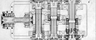
The final version of the tank of the “Object 490” tank: a – longitudinal section; b – plan view with the turret and hull roof removed; 1 — gun; 2 - tower; 3 – turret shoulder strap; 4 – automatic loader compartment cover; 5 – crew compartment; 6 – crew aft hatches; 7 – automatic loader compartment; 8 – power unit compartment; 9 – fuel compartment; 10 - tank body; 11, 16 — engines; 12, 15, 19, 20 – onboard gearboxes for transmitting power to the drive wheels of the front and rear contours; 13, 14, 18, 21 – drive wheels of front and rear contours; 17, 22 – tracks of front and rear contours
The main advantages of the project include the placement of the crew in the aft zone of the tank, in a highly protected capsule, which is least exposed to fire. It is interesting that sufficient attention was paid to the issues of its life support - according to the design, the crew compartment was equipped with heating and air conditioning systems, as well as a bathroom and a kitchenette. Also noted as positive was the ease of creating a family of vehicles based on the Object 490. With one or two engines, with convenient placement of troops or a target load, for example, a highly protected infantry fighting vehicle (here we can recall the Armata platform).
The collapse of the USSR put an end to the Object 490 project, which remained only on paper. Not even a full-size mock-up was built, so unfortunately the images posted online of this machine are merely a reconstruction or a model.
Reconstruction of the tank "Object 490"
We remind you that in our journal “Science and Technology” you will find many interesting original articles about the development of aviation, shipbuilding, armored vehicles, communications, astronautics, exact, natural and social sciences. On the website you can purchase an electronic version of the magazine for a symbolic 60 rubles/15 UAH.
In our online store you will also find books, posters, magnets, calendars with aircraft, ships, tanks.
Found a typo? Select a fragment and press Ctrl+Enter.
Tags: Land technology
Previous article Passenger trolleybuses produced in the USSR. Part 4. “Kyiv-3”, LAZ-695BT/“Kyiv-5”LA, ZiU-5G/ZIU-5D and others
Next article T-72, T-80 and T-90 - strength is in the details
Provided by SendPulse
Likes 0
Firepower
Although the tank is a versatile vehicle capable of hitting a variety of targets, its main task (in accordance with the main tank concept) is to combat heavily armored tank-type targets. The need to solve it determines the “look” and composition of the tank weapons complex, the type and characteristics of the main weapon. This concept continues to this day.
The main armament of the final version of the tank consisted of a 152 mm 2A73 cannon with a fully automated ammunition load of 32 unitary rounds located in two conveyors. Each conveyor had its own shot delivery system. Although the turret provided circular rotation, the elevation/declination angles of the gun relative to the horizon were -5°, +10° only in the range of heading angles ±45°. This drawback was compensated for by the use of a controlled hydropneumatic suspension, which, by changing the trim of the vehicle, makes it possible to increase the gun pointing angles in the vertical plane.
At the same time, the saturation of the battlefield with tank-dangerous manpower, armed with man-portable anti-tank weapons - RPGs, ATGMs, has increased significantly. The fight against such goals was given great attention when creating the Kharkov tank of the 21st century. Additional armament included two TKB-666 (TsKIB SOO) 2-barrel 7.62 mm machine guns (TsKIB SOO) with independent vertical guidance, located on both sides of the rear part of the armament block. Elevation angles (+45°) made it possible to hit targets located on the upper floors of buildings and in mountainous areas. The finished ammunition load for each machine gun was 1,500 rounds. On the rear turret, located above the crew capsule, there was a 30 mm automatic grenade launcher with horizontal guidance angles of 360°, vertical -10°, +45°).
The tank's control system was especially succinctly constructed. The sighting systems were built in the form of a separately located thermal imaging module and a laser rangefinder located on the right (along the tank) in the armored mask. The television module and the guided projectile guidance channel were located on the left. A panoramic sight with a visual channel was located on the rear turret; the image was transmitted to both the commander-gunner and the driver. The day-night TV panorama was placed on the automatic grenade launcher on the rear turret.
The modular installation of thermal imaging and television sights in the armored mask of the tank made it possible to place devices developed and mass-produced in the 80s, for example 1PN71 1PN126 “Argus”, etc., which had large overall dimensions, while drives for elevation and azimuth were not required, since the sights stabilized with the gun. Additional accuracy was achieved thanks to the “active” suspension, which reduced the load on the weapon stabilizer. The search for targets (when adjusted to the angle and loading position) could at the same time be carried out by an independent daytime panoramic sight and a day-night panorama installed on the weapons block of the second turret.
An interesting feature of the layout of the Object 490 tank was the use of the gun barrel as an OPVT air intake pipe (lifting height 4.6 m with a maximum elevation at the stern of 30°). Forward viewing cameras were installed on the frontal part of the hull, as well as on the fenders. The rearview camera was installed in the central part of the rear of the tank. Mortars of the “Tucha” system were installed on the sides of the tower - 12 pieces (c) btvt.info
Above the crew compartment of the Object 490 tank there was a second turret with additional weapons, a panoramic sight with a visual channel and a day-night television sight mounted on the machine along with an automatic grenade launcher. View of the stern - the second turret with explosive reactive armor units and additional weapons, the maximum gun elevation angle has been set. KAZ "Standard" mortars in the aft part and sides of the crew compartment. In the aft part of the compartment there are two crew hatches, the driver's hatch is equipped with a porthole for stowed driving (stern forward) (c) btvt.info
The limitations of the layout of the Object 490 tank include insufficient angles of declination of the gun on the side and stern (c) btvt.info
The problem of creating and mass production of compact tank sights with a thermal imaging channel could not be solved decades after the collapse of the USSR. At the moment, the problem is being solved by purchasing and licensed production of foreign components (in the Russian Federation). The level of technology development in the USSR and the Russian Federation is reflected by the 1PN126 device, adopted in 2005. It is difficult to imagine an “alternative history” of the development of technical vision systems in the USSR, if it had not collapsed, but one can hope for compactness and high performance, allowing one to abandon visual channel would be unfounded.
All-round visibility from the tank was planned to be implemented using forward-looking television cameras located on the upper frontal part of the hull's bow assembly and on the fenders, as well as rear-view cameras located in the center of the hull's rear. The crew also had prism observation devices with an image output above the eyepieces of the panoramic sight.
Object 490 “Advanced tank of the 21st century”© Andrey Tarasenko
Model of a 21st century tank.
In October 1984, the leadership of the GBTU and GRAU arrived at the KMDB, led by General Potapov and Bazhenov, to familiarize themselves with the development of the promising tank. The Object 490A was equipped with a 125 mm caliber gun (a 130 mm version was being developed), and talk about increasing the caliber had been going on for a long time. Disputes began about which caliber to choose - 140 mm or 152 mm. At this point, General Litvinenko, head of the NKT GRAU (Scientific Committee of the Main Artillery and Rocket Directorate), made a diagram very well and clearly demonstrating how effective the 152 mm caliber was for a tank. From that moment on, the 152 mm caliber was accepted for a future project, and no one ever returned to this issue
.
After the decision was made on the gun caliber of the promising tank, the existing versions of the Object 490 Topol and Object 490A Rebel tanks required a complete redesign.
The layout of the "Rebel" underwent changes, as a result of which the Object 477
", the layout of which was approved in 1985.
From the diaries of Yu. M. Apukhtin: 05/12/85.
...
Shomin finally approved the layout.
Kovalyukh ensured that the design of the automatic loader was not ring-shaped, but a closed circuit at the rear with ammunition fed from the body. Let's see what comes of this. Thus, the project returned to a close classic layout with the exception of the external weapons. A new variant of the "Object 490" by E. A. Morozov was in development in parallel with the "Boxer"/"Molot", and was also redesigned to be equipped with a 152 mm 2A73 gun.
This led to the creation of one of the most unusual and fundamentally new projects in the history of tank building, characterized by unparalleled levels of crew protection, mobility and firepower:
— crew protection with a level equivalent to ~2000 and ~4500 from BPS and CS, 200 and 600 from the upper hemisphere;
— 32 unitary shots L
=1400 in fully automated laying;
— engine power up to 2000 hp.
— possibility of movement if 2 caterpillar movers are damaged (on opposite sides).
E. A. Morozov.
Wooden model of the first version of the new layout of the Object 490 tank. 1:10. In the original version, the caterpillar propulsors were supposed to have 3+3 roller contours.
An early version of the layout with the crew placed in the rear of the tank
(The problem of reducing the number of crew of the main tank. Yu. M. Apukhtin, A. I. Mazurenko, E. A. Morozov, P. I. Nazarenko. VBTT. No. 6. 1980).
Description of the tank layout
The main principle implemented in this version is the conditional division of the entire vehicle into 5 compartments isolated from each other and their arrangement along the longitudinal axis from bow to stern in a sequence corresponding to their contribution and the combat effectiveness of the tank.
Placement of compartments of the "490" tank. Early version.
1 — fuel compartment;
2 — compartment of engine and power plant systems;
3 — main weapons compartment;
4 — automatic loader compartment;
5 - crew compartment.
The first is the fuel compartment with the minimum permissible level of armor protection against the most widespread weapons of destruction of the tank (700 and 1000 mm from the BPS and KS). Damage to this compartment, separated by longitudinal partitions, and partial loss of fuel in battle will not lead to the tank losing its combat effectiveness.
Behind the fuel compartment in the hull there is a compartment for the engine and power plant systems, and above it is the main weapons compartment. These compartments have a higher level of protection, since failure of the engine or gun significantly reduces the combat capabilities of the tank. The fuel compartment located in the bow of the hull serves as a screen for the power plant and increases its survivability during shelling. The power plant includes 2 identical engines (on the 5TDF model, in the future it was planned to install a 4TD). The hydrostatic transmission allows you to adjust the amount of power transferred to each track. This allows:
· use engines of moderate power (800-1000 hp) with high power of the power plant as a whole;
· continue driving if one of the engines is damaged by combat;
· reduce travel fuel costs by using one of the engines or both together, depending on road conditions.
· forward and reverse speeds are the same – more than 75 km/h, which significantly increases the tank’s survivability in battle.
Then the automatic loader compartment (A3) with ammunition is placed, which has an even higher level of protection and is shielded from frontal fire by the three previous ones, and in the upper belt by the main weapon compartment. Damage to this compartment, in addition to the tank losing its firepower, can lead to the detonation of charges with serious consequences. To neutralize the high pressures that arise in the event of detonation of charges, “knockout plates” are provided at the bottom of the compartment (in the roof in the first version), which act as a safety valve. The length of compartment A3 provides the possibility of placing unitary ammunition ( L
=1400 mm) and makes it possible to simplify the kinematics of feeding and distributing ammunition into the gun chamber. In the first version of the tank's layout, AZ shots were placed vertically in conveyors (32 shots), entering a centrally located dispenser mechanism for 4 shots, and in the final version - horizontally.
The last part of the tank is the crew compartment. The crew is located in a comfortable position - sitting, ensuring all ergonomic requirements (bathroom, heating, air conditioning, cooking). On the roof, in the second tower, there is a complex of electro-optical means for searching for targets and controlling the main and additional weapons. This tank layout ensures differentiation of the level of protection and survivability of individual tank components in accordance with their importance.
An interesting feature of the layout is the use of the gun barrel as an OPVT air intake pipe (lift height 4.6 m with a maximum elevation at the stern of 30°).
The new version of the promising tank differed from the original in its solutions for armor protection, automatic loader and tracked propulsion (4+2 rollers).
A variant of a promising tank (development ~1989-91).
Armament: 150 mm 2A73 cannon, automatic loader with two horizontally located conveyors.
Additional weapons are a 30 mm grenade launcher on the rear turret and two 2x7.62 mm TKB-666 machine guns.
Along the perimeter of the tank and in the shafts between the sides of the crew compartment, 26 KAZ “Standard” mortars are placed to destroy targets attacking from above.
Placement of compartments of the "490" tank. Option for publication in VBTT No. 7. 1991, latest publication by E. A. Morozov.
When developing the project, much attention was paid to protection from ammunition attacking from above.
1 — fuel compartment;
2 — compartment of engine and power plant systems;
3 — main weapons compartment;
4 — automatic loader compartment;
5 - crew compartment.
Firepower
Although the tank is a versatile vehicle capable of hitting a variety of targets, its main task (in accordance with the main tank concept) is to combat heavily armored tank-type targets. The need to solve it determines the “look” and composition of the tank weapons complex, the type and characteristics of the main weapon. This concept continues to this day.
The main armament of the final version of the tank consisted of a 152 mm 2A73 cannon with a fully automated ammunition load of 32 unitary rounds located in two conveyors. Each conveyor had its own shot delivery system. Although the turret provided circular rotation, the elevation/declination angles of the gun relative to the horizon were -5°, +10° only in the range of heading angles ±45°. This drawback was compensated for by the use of a controlled hydropneumatic suspension, which, by changing the trim of the vehicle, makes it possible to increase the gun pointing angles in the vertical plane.
At the same time, the saturation of the battlefield with tank-dangerous manpower, armed with man-portable anti-tank weapons - RPGs, ATGMs, has increased significantly. The fight against such goals was given great attention when creating the Kharkov tank of the 21st century. Additional armament included two TKB-666 (TsKIB SOO) 2-barrel 7.62 mm machine guns (TsKIB SOO) with independent vertical guidance, located on both sides of the rear part of the armament block. Elevation angles (+45°) made it possible to hit targets located on the upper floors of buildings and in mountainous areas. The finished ammunition load for each machine gun was 1,500 rounds. On the rear turret, located above the crew capsule, there was a 30 mm automatic grenade launcher with horizontal guidance angles of 360°, vertical -10°, +45°).
The tank's control system was especially succinctly constructed. The sighting systems were built in the form of a separately located thermal imaging module and a laser rangefinder located on the right (along the tank) in the armored mask. The television module and the guided projectile guidance channel were located on the left. A panoramic sight with a visual channel was located on the rear turret; the image was transmitted to both the commander-gunner and the driver. The day-night TV panorama was placed on the automatic grenade launcher on the rear turret.
The modular installation of thermal imaging and television sights in the armored mask of the tank made it possible to place devices developed and mass-produced in the 80s, for example 1PN71 1PN126 “Argus”, etc., which had large overall dimensions, while drives for elevation and azimuth were not required, since the sights stabilized with the gun. Additional accuracy was achieved thanks to the “active” suspension, which reduced the load on the weapon stabilizer. The search for targets (when adjusted to the angle and loading position) could at the same time be carried out by an independent daytime panoramic sight and a day-night panorama installed on the weapons block of the second turret.
An interesting feature of the layout is the use of a gun barrel
as an air intake pipe OPVT (lifting height 4.6 m with a maximum elevation at the stern of 30°).
Forward viewing cameras were installed on the frontal part of the hull, as well as on the fenders. The rearview camera was installed in the central part of the rear of the tank.
On the sides of the tower were installed mortars of the “Tucha” system - 12 pieces.
Above the crew compartment there was a second turret with additional weapons, a panoramic sight with a visual channel
and a day-night television sight mounted on the machine along with an automatic grenade launcher.
View of the stern - the second tower with explosive reactive armor units and additional weapons.
Maximum gun elevation angle.
KAZ "Standard" mortars in the aft part and sides of the crew compartment.
In the aft part of the compartment there are two crew hatches, the driver's hatch is equipped with a porthole
for driving in a stowed manner (stern first).
Limitations of the layout include insufficient angles of declination of the gun on the side and stern.
The problem of creating and mass production of compact tank sights with a thermal imaging channel could not be solved decades after the collapse of the USSR. At the moment, the problem is being solved by purchasing and licensed production of foreign components (in the Russian Federation). The level of technology development in the USSR and the Russian Federation is reflected by the 1PN126 device, adopted in 2005. It is difficult to imagine an “alternative history” of the development of technical vision systems in the USSR, if it had not collapsed, but one can hope for compactness and high performance, allowing one to abandon visual channel would be unfounded.
All-round visibility from the tank was planned to be implemented using forward-looking television cameras located on the upper frontal part of the hull's bow assembly and on the fenders, as well as rear-view cameras located in the center of the hull's rear. The crew also had prism observation devices with an image output above the eyepieces of the panoramic sight.
On the topic, see - The evolution of tank sights - from mechanical sights to fire control systems.
An example image on the Argus monitor screen (level 90s). It was premature to abandon the visual channel.
Protection
4.04.74
.
Proskuryakov (VNIITM):
— The protection must be differentiated and provide a firing angle of ±25 .. 35 degrees. Types of protection: armor, active protection and camouflage. The armor should be significantly increased compared to the “225” and “226” products.
It is necessary to provide protection against a 120 mm NATO projectile with an increased initial velocity. There is no tank without armor. Protection should be solved not through thickness, but through new solutions
.
Maneuverability should be increased due to a hydromechanical transmission. Isakov is now making it together with VNIITransmash with a power of 1500 hp. This should increase average driving speeds, reduce acceleration time, improve controllability, smoothly change the turning radius of the machine, and ensure maximum reverse speed
.
21st century tank layout solutions have placed a key emphasis on ensuring that tank components are protected according to their contribution to combat effectiveness. If the first (fuel) compartment had frontal projectile protection at the level specified by the TTT, then the last compartment (crew) will be practically protected 2-2.5 times stronger. Since the creation of shells with such a level of armor penetration is impossible in the foreseeable future, the specified construction of the layout scheme makes it possible to ensure a high probability of tank survival in battle with a minimum mass of armor.
View from above.
Ranking of the main tank systems according to their contribution to survivability
System
| Damage upon defeat | Possibility of reservation | TO | |
| Crew | Complete failure | Spare crew (while maintaining the technical serviceability of the tank) | 1,0 |
| Ammunition | Irreversible tank losses (in case of explosion) | Reservation is not possible | 0.9 |
| Firing complex (combat compartment) | Loss of the ability to defeat the enemy | Additional weapons, simplified backup fire control system, semi-automatic control of the automatic loader | 0,8 |
| Engine-transmission unit | Loss of mobility | Reserve power unit of reduced power | 0.6 |
| Fuel | Reduced cruising range Irreversible loss of the tank (in case of fuel fire) | Reserve fuel tank Redundancy not possible | 0.5 |
Tank diagram (in plan) with sequentially placed compartments:
1 — sheet of the bow; 2 — fuel compartment; 3 — fuel partition;
4 — engine compartment; 5 — motor partition; 6 — combat compartment; 7 — ammunition rack partitions; 8 — ammunition compartments; 9 — crew compartment partition; 10 — crew compartment; 11 — angle of fire with the most powerful lethal weapons α
The approach to protecting a promising tank is described in the article by A. I. Mazurenko and E. A. Morozov. P. I. Nazarenko “Ways to increase the survivability of a tank.”
Development of the “490” project.
1 and 2 – with vertical placement of shots in two AZ conveyors and a dispensing mechanism in the center, knockout plates are made in the roof of the AZ compartment;
3 – with horizontal placement in two conveyors. Knockout plates are made in the bottom of the AZ compartment.
This direction of development was laid down by A. A. Morozov back in the 70s, after the completion of the design and the start of large-scale production of the T-64A tank. The solutions are described in detail in the diary entries on the design of the Object 450 tank on Topic 101.
In an early version of the project, the protection of the upper part of the bow assembly of the hull included an 80 mm thick steel plate installed at an angle of 60°. A removable package (170 mm/60°) with tandem-installed active protection elements, which were separated by a 50 mm steel plate, was installed on the plate. In its concept, such protection was similar to the Duplet remote sensing module currently installed on the Oplot tank.
The tower protection was a combined structure with spaced (armored mask) armor combined with active elements (front and sides).
The equivalent of protection from the upper hemisphere is 180...200 from explosive weapons and 600 from cumulative ammunition. The only weak point of the tank was the turret in its central part, where the armor was 50 mm (5°). However, even if this area was hit by cumulative ammunition or explosive devices, only one of the engines could be disabled.
The roof of the ammunition compartment was a combined structure with active elements and multi-layer armor; in the final version, “knockout plates” were made in the bottom to reduce weakened protection zones from above.
The outer and central parts in the protective structures of the hull and turret were made of high-hardness steel, and the inner parts were made of medium-hardness steel. This made it possible to reduce the formation of fragmentation flow when penetrating armor elements.
The final version of the 21st century tank described (P.F. Gnedash, L.I. Mazurenko, E.A. Morozov. A possible variant of an unconventional tank layout. Bulletin of Armored Vehicles, No. 7. 1991) was protected by combined armor (steel + filler + steel) located at an angle of 80°. The part formed the protection of the upper and middle protection belt of the tank.
a – longitudinal section; b – plan view with the turret and hull roof removed; 1 — gun; 2 - tower; 3 – turret shoulder strap; 4 – automatic loader compartment cover; 5 – crew compartment; 6 – crew aft hatches; 7 – automatic loader compartment; 8 – power unit compartment; 9 – fuel compartment; 10 - tank body; 11, 16 — engines; 12, 15, 19, 20 – onboard gearboxes for transmitting power to the drive wheels of the front and rear contours; 13, 14, 18, 21 – drive wheels of front and rear contours; 17, 22 – tracks of front and rear contours.
The protection scheme included a layer of active protection elements with a combined scheme with longitudinal compression of the filler (steel + EDZ + filler), increasing protection by ~40%. The total armor dimensions were 260 mm. The design provided protection not only from ammunition attacking horizontally, but also protection from ammunition (CU, cumulative) attacking from above.
The tank compartments were insulated and separated by partitions - 20 mm for the fuel compartment and engine systems. 20 mm partition between 1 and 2 engines. Partitions with a size of 50 mm were installed in front of the ammunition compartment and the crew capsule. An evacuation hatch was provided at the bottom of the crew capsule, which also served as a sanitary unit.
The hull bottom armor was also differentiated 20, 50 and 100 mm (combined) in the fuel and engine compartment areas; ammunition compartment; crew capsules.
Promising protection devices developed by the Steel Research Institute (90s).
Below in the center is a photo of the perspective element DZ 32E, on the left is the “Corrugation” element.
The overall dimensions of the promising active element were half the size of the serial 4S22.
This made it possible to provide a larger coverage area for the protected projections.
Mobility
Located in the middle part of the tank, in front of the fighting compartment, the power plant provided additional protection for the crew. The four-track chassis, due to this layout, significantly increases the survivability of the tank during a mine explosion. Increased survivability is also facilitated by the separate design of systems serving each engine.
On the basis of a tank with two engines, you can create a family of vehicles using one or two engines, depending on the type and purpose of the vehicle, the weight and power consumed by the attachments.
The requirements for tank mobility are constantly increasing. It is assumed that the average speed of a tank in the near future when driving on dry dirt roads should reach 50...55 km/h. To achieve such a speed, the specific power of the tank must be at least 21...23 kW/t, and the maximum speed provided by the transmission speed range is 80...90 km/h.
Overcoming natural obstacles and artificial barriers, making passages using mounted and built-in equipment require an additional increase in the power of the power plant.
One of the important measures to protect a tank is to increase mobility in order to effectively maneuver under fire (including in reverse, without exposing the vulnerable stern). Research shows that due to defensive maneuvering on the battlefield, the probability of hitting a tank is reduced by 2-4 times, and security is increased by 1.5-2 times. This applies in particular to protection against guided missiles.
Thus, to increase the mobility of a tank with a predicted weight (over 54 tons), a power plant with a power of 1320...1470 kW is required.
High dynamic qualities of tanks in the specified power range, combined with good fuel efficiency at low loads, can be ensured by engines with two power levels (4TD - 800 and 1000 hp).
The second, lower, power level is necessary for economical operation of the tank at limited speeds and relatively easy road conditions.
For a promising tank, a power plant with two identical engines located in the middle part of the tank, on-board hydrostatic-mechanical transmissions and a hydrostatic drive of the turning mechanism can be used. The reverse mechanism provides the ability to move forward and reverse at the same speeds
.
The marching movement of the tank in a column was supposed to be carried out stern forward. The driver's mechanic's aft hatch had a porthole and a rearview TV system. The chair was swivel.
Running layout of the chassis and control system "490".
Running mock-up of a tank chassis with a power plant with two engines and a 4-track undercarriage:
1 — cabin, 2 — front part; 3 - rear part.
The model is made on the basis of two T-64A tanks with a 5TDF engine. The tanks have the upper part of the hull with the fighting compartments cut out; The control and engine compartments are connected into a single module. Connected by the aft parts, they form a running layout with two engines and four tracked lines.
The mass of the model is 35.6 tons. The final drives of the rear part of the model are modernized so that they provide movement at a speed corresponding to the speed of the front part. The engine control system is installed in the front part of the model.
Diagram of a tank chassis with a power plant having two engines:
1- drive wheel; 2 - guide wheel; 3 – final drive; 4 — hydrostatic-mechanical transmission; 5 — GOP gearbox; 6 — reverse with reduction gear; 7 - engine; 8 — hydrostatic drive of the turning mechanism
Each engine developed a power of 590...660 kW with a short-term boost to 740 kW. Thus, the total power of the power plant reaches 1180...1320 kW, and the specific power of the prototype is 33...37 kW/t. This will provide the tank with a power density of 29 kW/t.
With this arrangement, there will be no need for lengthy development of a new high-power tank engine. The proposed scheme increases the durability and fuel efficiency of the power plant due to the rational use of the power of one or both engines. For more details, see the article Tank power plant with two engines.
Elements of the tank chassis of the “Object 219” type (rollers).
Options for the tank were developed with ejection, combined and fan cooling systems.
Return to origins – 4TD
4TPD engine, preliminary design 1953
Doctoral dissertation by A.D. Charomsky - strategic line for the development of tank engine building in the USSR in the post-war years
For a promising tank of the 21st century, it was planned to use the 4TD engine, based on technologies developed on the serial 6TD-2 engine. The installation of two 6TD-2 engines was excessive in power; in addition, to reduce dimensions, it was optimal to install two smaller engines. The creation of a new 4TD engine in the 80s did not have any risky technical aspects, taking into account 6TD technologies and the absence of problematic issues of imbalance of 5TD and 3TD. 4TD developed power in nominal and forced modes of 800 and 1000 hp.
It took many years for tank developers who were once in conflict on the territory of the USSR to come to the conclusion -
«And as a result of our joint work with the Kharkov residents, an agreed decision was made to adopt for subsequent development a single MTO with the Kharkov 6TD-2 engine, but with all tank engine systems created by the Tagil residents
».
E.B. VAVILONSKY (head of the power plant department, leading designer of the new design department of UKBTM). Source - Chief Designer Vladimir Potkin. Tank breakthrough. Digest of articles. – Nizhny Tagil: LLC Advertising and Publishing Group “DiAl”, 2013.
Another confirmation of the correct direction chosen by Morozov was the demonstration in October 2022 at the AUSA symposium of a project for a promising engine for US armored combat vehicles, created as part of the “Advanced Combat Engine” program. It turned out to be an American “analog” of 4TD created using modern technologies -
"Advanced Combat Engine" showcased at AUSA 2022. The 14.3L flat-four engine was developed for the US Army's TARDEC (Tank Automotive Research, Development and Engineering Center) in partnership with Cummins. Power 1000 hp at 2400 rpm. The engine is part of a 30-year modernization strategy for American armored vehicles.
Advantages of the 21st century tank project by A. A. Morozov.
1. Maximum possible crew protection within the weight limits of ~55 tons.
2. Placement of the crew in the aft zone of the tank, least exposed to fire, in a highly protected capsule.
3. A simple and concise layout of sighting systems, corresponding to the level of development of science and technology in the short term. The presence of a visual channel in a panoramic sight with visibility from the highest point of the tank.
4. Application of a simple automatic loader circuit without restrictions on shot length L
=1400 (active part of the BPS up to 1300 mm) with full automation of ammunition. The entire ammunition load of the main armament is fully mechanized and placed in a single automatic loader with a simple trajectory and kinematics for delivering a shot to the gun breech.
5. Possibility of moving forward and backward at the same speeds (75 km/h).
6. Ease of creating a family of vehicles with 1 or 2 engines and convenient placement of troops and target load. For example, a highly protected infantry fighting vehicle. A significant impact on the appearance of the tank, along with fundamental decisions of the main components and systems, can be exerted by: reducing the functional tasks solved by tanks in battle; adaptation of the tank design as a base vehicle for the VGM family and to mass production conditions; the need to maintain the possibility of further improvement during the life cycle of the machine.
7. In order to increase survivability, the chassis has a 4-circuit with a drive for each circuit. This makes it possible for the tank to not lose mobility if one of the lines (or even two on different sides) breaks.
8. Maximum protection of the crew capsule from the entire range of destructive agents, including chemical, bacteriological and radiation exposure, comfort in the habitable compartment (availability of sanitary facilities, devices for heating food and air conditioning). Co-location of the crew radically solves the issues of mutual assistance and interchangeability, significantly simplifies the issues of internal communication and duplication of tank crew functions.
9. Maximum mine protection for the tank and crew members;
10. The tank’s power plant can operate in two modes:
1) maximum power - when driving and difficult road conditions and in combat;
2) in partial mode (~50% Mmax - when driving on good dirt roads and paved roads. Both modes should be equivalent in terms of efficiency, ensuring minimum specific fuel consumption. This is the most radical way to increase the cruising range of a tank with a limited amount of transported fuel .
11. Replacing the torsion bar suspension with a hydropneumatic one, in addition to solving the main problem - increasing average speeds by improving the smoothness of the ride - makes it possible to control the tank's ground clearance, which increases its maneuverability and survivability in battle. In addition, the controlled hydropneumatic suspension, by changing the trim of the vehicle, makes it possible to increase the gun pointing angles in the vertical plane. Thus, the introduction of only one system increases the indicators of mobility (direct effect), security and firepower of the sneaker (side effect).
On this topic:
Object 490A "Rebel"
Object 490 “Topol”
Object 299 (JSC Spetsmash)
Tank T-14 "Armata" Heavy infantry fighting vehicle T-15 Object 195 "T-95" (JSC "UKBTM") Object 640 "Black Eagle" (JSC KBTM) Development of a unified combat compartment, theme "Burlak" (JSC "KBTM")
Intercontinental ballistic missile "Topol-M"
The RT-2PM2 "Topol-M" complex (code RS-12M2, according to NATO classification - SS-27 Sickle "Sickle") is a Russian strategic missile system with an intercontinental ballistic missile, developed in the late 1980s - early 1990s based on the RT-2PM Topol complex. The first intercontinental ballistic missile developed in Russia after the collapse of the USSR. Adopted into service in 1997. The lead developer of the missile system is the Moscow Institute of Thermal Engineering (MIT).
The rocket of the Topol-M complex is a solid-fuel, three-stage missile. The maximum range is 11,000 km. Carries one thermonuclear warhead with a power of 550 kt. The missile is based both in silo launchers (silos) and on mobile launchers. The silo-based version was put into service in 2000.
Designed to carry out tasks of delivering a nuclear strike on enemy territory in the face of counteraction from existing and future missile defense systems, with multiple nuclear impacts on a positional area, when blocking a positional area with high-altitude nuclear explosions. It is used as part of the 15PO65 silo-based and 15P165 mobile-based complexes.
The Topol-M stationary complex includes 10 intercontinental ballistic missiles mounted in silo launchers, as well as a command post. Main characteristics of the Topol-M rocket
| Number of steps | 3 |
| Length (with MS) | 22.55 m |
| Length (without MS) | 17.5 m |
| Diameter | 1.81 m |
| Launch weight | 46.5 t |
| Throwing weight | 1.2 t |
| Type of fuel | Solid mixed |
| Maximum range | 11000 km |
| Head type | Monobloc, nuclear, detachable |
| Number of warheads | 1 + about 20 dummies |
| Charge power | 550 Kt |
| Control system | Autonomous, inertial based on BTsVK |
| Based method | Mine and mobile |
The Topol-M mobile complex consists of one missile placed in a high-strength fiberglass transport and launch container (TPK), mounted on an eight-axle MZKT-79221 cross-country chassis and is structurally practically no different from the silo version. The weight of the launcher is 120 tons. Six pairs of eight wheels are swivel, providing a turning radius of 18 meters.
The ground pressure of the installation is half that of a conventional truck. Engine V-shaped 12-cylinder turbocharged diesel engine YaMZ-847 with a power of 800 hp. The depth of the ford is up to 1.1 meters.
When creating systems and units of the mobile Topol-M, a number of fundamentally new technical solutions were used in comparison with the Topol complex. Thus, the partial suspension system makes it possible to deploy the Topol-M launcher even on soft soils. The maneuverability and maneuverability of the installation have been improved, which increases its survivability.
"Topol-M" is capable of launching from any point in the positional area, and also has improved means of camouflage, both against optical and other reconnaissance means (including by reducing the infrared component of the complex's unmasking field, as well as the use of special coatings that reduce radar signature).
The intercontinental missile consists of three stages with solid propellant propulsion engines. Aluminum is used as fuel, ammonium perchlorate acts as an oxidizing agent. The step bodies are made of composites. All three stages are equipped with a rotating nozzle to deflect the thrust vector (there are no lattice aerodynamic rudders).
The control system is inertial, based on the on-board central control system and a gyro-stabilized platform. The complex of high-speed command gyroscopic devices has improved accuracy characteristics. The new BTsVK has increased productivity and resistance to the damaging factors of a nuclear explosion. Aiming is ensured through the implementation of autonomous determination of the azimuth of the control element installed on a gyro-stabilized platform using a ground-based complex of command instruments located on the TPK. Increased combat readiness, accuracy and continuous operation life of on-board equipment are ensured.
The launch method is mortar for both options . The rocket's sustaining solid-propellant engine allows it to gain speed much faster than previous types of rockets of a similar class created in Russia and the Soviet Union. This makes it much more difficult for missile defense systems to intercept it during the active phase of the flight.
The missile is equipped with a detachable warhead with one thermonuclear warhead with a capacity of 550 kt of TNT equivalent. The warhead is also equipped with a set of means to overcome missile defense. The complex of means for overcoming missile defense consists of passive and active decoys, as well as means of distorting the characteristics of the warhead . Several dozen auxiliary correction engines, instruments and control mechanisms allow the warhead to maneuver along the trajectory, making it difficult to intercept it at the final part of the trajectory.
False targets are indistinguishable from warheads in all ranges of electromagnetic radiation (optical, laser, infrared, radar). False targets make it possible to simulate the characteristics of warheads according to almost all selection criteria in the extra-atmospheric, transitional and significant part of the atmospheric section of the descending branch of the flight trajectory of missile warheads, and are resistant to the damaging factors of a nuclear explosion and the radiation of a super-powerful nuclear-pumped laser. For the first time, decoys have been designed that can withstand super-resolution radars.
In connection with the termination of the START-2 treaty, which prohibited the creation of multi-charge intercontinental ballistic missiles, the Moscow Institute of Thermal Engineering is working on equipping Topol-M with multiple independently targetable warheads. Perhaps the result of this work is the RS-24 Yars. A mobile version of this complex, placed on the chassis of an eight-axle tractor MZKT-79221, is being tested.
The high resistance of the 15Zh65 missile to the effects of potential enemy missile defense systems is achieved due to:
- Reducing the time and length of the active section through extremely rapid acceleration of the rocket. Acceleration time to final speed (over 7 km/s) is less than 3 minutes.
- The missile’s ability to maneuver in the active section, complicating the enemy’s solution to the interception task, as well as to perform a program maneuver when passing through the cloud of a nuclear explosion
- Newly developed protective coating for the hull, providing comprehensive protection against the damaging factors of a nuclear explosion and weapons based on new physical principles.
- A complex for overcoming missile defense, including passive and active decoys and means of distorting the characteristics of the warhead. LCs are indistinguishable from warheads in all ranges of electromagnetic radiation (optical, laser, infrared, radar), they allow simulating the characteristics of warheads according to almost all selection criteria in the extra-atmospheric, transitional and significant part of the atmospheric section of the descending branch of the flight trajectory of missile warheads, up to altitudes 2 - 5 km; are resistant to the damaging factors of a nuclear explosion and radiation from a super-powerful nuclear-pumped laser, etc. For the first time, LCs have been designed that can withstand super-resolution radars. Means for distorting the characteristics of the warhead consist of a radio-absorbing (combined with heat-protective) coating of the warhead, active jammers, etc. The radar signature of the warhead is reduced by several orders of magnitude, the ESR is 0.0001 sq.m. Its detection range has been reduced to 100 - 200 km. The optical and IR visibility of the BB is extremely reduced due to the effective cooling of the BB surface in the trans-atmospheric section and the reduction in the luminosity of the BB's wake in the atmospheric section, achieved incl. due to the injection of special liquid products into the trace area that reduce the intensity of radiation. As a result of the measures taken, it is possible to overcome the monoblock warhead of a promising multi-echelon missile defense system with space-based elements with a probability of 0.93 - 0.94. The high- and sub-atmospheric missile defense section is overcome with a probability of 0.99, the atmospheric one with a probability of 0.93 - 0.95.
The 15Zh65 rocket is equipped with a thermonuclear monoblock warhead with a power of 0.55 MGt. Tests of ICBMs with MIRVs (from 3 to 6 multiple warheads with a capacity of 150 kt.) have been carried out. In the future, it is planned to equip the missile with a maneuvering warhead (tests of which were also successfully carried out in 2005 and continue), and therefore the possibility of intercepting warheads, according to Russian specialists will be practically reduced to zero.
The probable circular deviation is no more than 200 m, which allows the half-megaton power warhead to confidently hit highly protected point targets (in particular, command posts and silos). Due to the limited throw weight, which limits the power of the nuclear warhead, the Topol-M missile, unlike the 15A18 Voevoda (the power of the monoblock warhead of which was 20-25 MGt), has limitations in carrying out destructive effects on a large area target.
The mobile-based 15P165 complex has unique initial survivability characteristics and is capable of operating covertly and autonomously for a long period of time. The patrol area of the complex is 250,000 sq. km.
Topol-M missile is unified with the Bulava , created to arm the Project 955 SSBN. The Bulava’s competitor is the R-29RMU2 Sineva liquid-fueled ICBM. It is significantly superior to the Bulava (like all other ICBMs) in terms of energy and mass sophistication, but is inferior in terms of an important criterion for Russian sea-based missiles - survival in the active phase due to the lower acceleration speed and greater vulnerability from laser weapons, characteristic of liquid-propellant missiles compared to solid fuel. However, the Bulava rocket, with a launch weight of about 37 tons, is significantly inferior in striking power to existing heavier solid-fuel rockets, including the Trident-2 rocket with a launch weight of 59 tons. (Bulava warhead - 6x150 kt, Trident-2 (theoretically) - 8x475 kt). The project to equip the naval component of Russia's nuclear forces with SSBNs with light ballistic missiles "Bulava" is criticized by experts who point to the need to arm domestic SSBNs with high-tech solid-fuel SLBM R-39UTTH, the testing of which was curtailed in the 90s. and which, if put into service, would have no analogues in the world among SLBMs in terms of striking power and flight performance.
Transportation of the Topol-M rocket and loading into the silo
Transportation and loading into the intercontinental ballistic missile silo of the 5th generation RT-2PM2 Topol-M .
Location: 60th Taman Order of the October Revolution Red Banner Missile Division.
"Object 490A": two versions of one promising tank
In the history of domestic tank building, the eighties became a period of active search for new unusual layout and design solutions. A lot of interesting ideas were then proposed and worked on by the Kharkov Design Bureau for Mechanical Engineering (KMDB). Some of them were implemented in two versions of the project “490A” or “Rebel”. However, both versions of the project never made it out of the early stages.
One of the few photos of the running mock-up of the MBT “490M”
Parallel projects
Since the late seventies, KMDB has been working on the MBT project with the code “Object 490”.
It developed already known ideas and proposed new ones. At the same time, a tank with the index “490A” and the name “Rebel” was being developed. This project also included bold decisions, but some proposals with dubious prospects were abandoned. In particular, for the MBT “490” it was planned to reduce the crew to two people with a corresponding restructuring of electronics and other equipment. In the 490A project they abandoned this and retained the third tanker. The rest of the project was no less bold and also involved the use of uncharacteristic solutions.
The design and subsequent testing of two types of MBTs were supposed to take several years. In the early nineties, the issue of adopting the equipment into service could have already been decided. However, work on the “Object 490A” was delayed - after testing the first prototype, it was decided to significantly rework the project.
First version
In 1982, KMDB completed the preparation of documentation for the first version of “Rebel”. A wooden model was built in accordance with it. Soon a running prototype appeared, and then a full-fledged prototype intended for comprehensive testing.
View of the other side
“Object 490A” received a hull of a traditional layout with a monitor-type turret. The commander and gunner were located below the level of the hull roof, which made it possible to reduce the dimensions of the turret. In the bow of the hull, behind a powerful frontal barrier, there was a control compartment and a fuel tank. The right half of the fighting compartment was occupied by automatic loading.
The main weapon of the "Rebel" was to be a 125-mm smoothbore gun, which was a further development option for the serial product 2A46. The gun received remote control and was equipped with automatic loading. The separately loaded rounds were located in a mechanized stowage inside the fighting compartment. The mechanisms were responsible for their extraction, lifting to the gun and sending.
In order to increase the ammunition load, various proposals were worked out. A new layout of the automatic loader with the most dense layout was created. The concept of the so-called charge of changeable shape. She proposed abandoning the rigid cartridge case with a charge, the role of which was assigned to a soft cap. The flexible cap could change shape when loaded into the stack or when sent to the chamber, which made it possible to optimize the use of available volumes.
Placing the crew inside the hull under the turret placed special demands on surveillance equipment and the fire control system. It was proposed to equip the MBT with the necessary viewing and sighting devices built using optical fiber. Fiber made it possible to simplify the design of surveillance equipment, reduce the projection of viewing devices, and also ensure their optimal placement without dead zones.
Layout of tank compartments
“Object 490A” has successfully reached the stage of construction and testing of a prototype. In 1983-84. The prototype was tested at the test site and conclusions were drawn. Some technical solutions were approved, while others needed further development. In addition, the MBT was now subject to updated requirements, which resulted in a significant redesign of the project.
Special forces of the Russian Federation and the USA: a race of improvements
Second version
The increase in firepower of the modernized 125 mm gun was considered insufficient to guarantee a guaranteed solution to combat missions.
In this regard, the second version of the Object 490A was rebuilt to accommodate a more powerful 152 mm smoothbore gun. The use of a new weapon entailed a restructuring of the fighting compartment. Other adjustments were also made related to the results of past tests. The layout of the vehicle as a whole remained the same, but the fighting compartment was seriously altered. The gun remained in the remote installation, and the automatic loader devices were now located under it. The commander and gunner's seats were placed at the sides of the squad - on the sides of the automation.
Mechanized stowages for caseless shots with ZIF were located in the front and rear of the compartment. A ring conveyor ran under them and under the tankers' seats. At the rear of the turret there was a lift for feeding shots to the cannon. For all its complexity and large volume, the proposed automatic loader could hold 40 rounds.
From the point of view of the control system, the new 490A tank was significantly different from the old one. Fiber optics performed poorly in testing and was replaced by standard appliances and television devices. It was proposed to introduce active protection complex equipment into the on-board electronics. Its radar was to be mounted on the sides of the turret, and the automatic control system was to be mounted inside the tank.
The updated Rebel project was ready in 1984. It was possible to build mock-ups and a prototype, conduct tests and draw conclusions. But none of this happened. Tests of the previous prototype showed the presence of some unresolved problems. The new project also had shortcomings. As a result, the development path of the MBT was soon seriously revised, and the 490A project had to be closed.
Excessive courage
The development of Object 490A faced a number of characteristic problems directly related to new bold technical solutions.
Some new components performed poorly in testing, while others required development and lengthy refinement. All this predetermined the fate of the project. While it was planned to equip the "Rebel" with a 125-mm cannon of increased power, the main tasks and problems were related to the automatic loader. The proposal to switch to a large caliber with a fundamentally new shot led to new difficulties. It turned out that creating a ZIF shot suitable for practical use is an extremely difficult task.
Until the end of the development of such ammunition, all work on the 152 mm gun did not make much sense. Moreover, by the mid-eighties, the ZIF idea was abandoned and they returned to proven loading principles.
Optical fiber in observation and aiming devices has not justified itself. Existing and available materials did not provide the required resolution of the optics and reduced its actual efficiency. The lack of prospects in this direction led to the fact that the second version of the Object 490A used “traditional” optics.
Placement of units in the first version of the project
Added to this was the need to improve protection, develop new fire control devices, improve the power plant, etc. Thus, despite all the visible advantages and prospects, the new MBT turned out to be too difficult to develop - and subsequently difficult to build.
Developments for the future
Further development of the 490A project was considered inappropriate.
As proposed, the second version of the project had a number of shortcomings, the elimination of which required too much effort. In this regard, we decided to abandon the development of “Rebel” and launch a new project that takes into account the accumulated experience. Already in 1984, work began on a new main tank with the index “477” and the name “Boxer”. In some features it resembled “Rebel”, but otherwise it was an independent development. It also used new original design ideas of various kinds.
By this time, within the framework of the 490A project, only a prototype and an experimental tank had been built, which were tested in 1983-84. After the development of the second version of the Object 490A began, this technique remained out of use. She was transferred to storage with no prospect of returning to work. According to various sources, the running model still exists, but in the past it was dismantled. Now the most interesting product is a pitiful sight.
Nevertheless, this machine did important work in its time and showed real prospects for certain technical solutions. Such conclusions allowed us to adjust new projects. However, a completely new era was on the horizon, and most of the developments on the Object 490A simply disappeared.