Purpose: CRRS R-419 L1 is intended for organizing independent radio relay communication lines, as well as for branching channels from multi-channel radio relay, tropospheric and wire communication lines.
The station provides operation on anchor lines via 6 channels of HF equipment P-330-6 with the ability to re-receive via HF channels of P-340 GMN equipment on communication lines up to 120 km long in the range of 390-645 MHz, and in digital modes on communication lines up to 400 km in the range 390-645 MHz and up to 1500 km in the range 1550-1850 MHz.
Operation at the R-419 L1 radio relay station in terminal and relay modes
At a station prepared for operation in analogue mode
- Turn on the station and check the presence of supply voltage;
- check the operation of both half-sets of the “push” section;
- make electrical measurements of the parameters of connecting lines;
- enter into contact with the correspondent with two half-sets in the terminal mode, measure the RF level reserve;
- adjust the receiving levels of group paths and the residual attenuation of PM channels;
- measure the frequency response of the residual attenuation of two PM channels of each half-set, the noise level in the channels, evaluate the noise saturation of the channels and submit them to a special equipment room for classification or cross-connection;
- switch the station to relay mode and make sure the communication is going through;
- make the necessary entries in the hardware log.
At a station prepared for operation in digital mode
- Turn on the station and check the presence of supply voltage;
- check the operation of both half-sets of the “push” section;
- make electrical measurements of the parameters of connecting lines;
- enter into contact with the correspondent with two half-sets in the terminal mode, measure the RF level reserve;
- monitor the condition of receiving paths and communication quality;
- hand over digital channels to a special equipment room for classification or cross-linking;
- switch the station to relay mode and make sure the communication is going through;
- make the necessary entries in the hardware log.
A drone powered by microchip has been successfully tested in Japan.Microwave-powered drone successfully tested in Japan
A scientific team from Japan was able to successfully fly a small drone into the sky that used microwave energy to power its electric motors and thus successfully completed test flights. This experiment will be discussed in the current material. Microwaves and the prospect of their use in the future As is known, at the moment most rockets fly on liquid or solid fuel. And at the same time, the weight of the substance necessary for flight can be up to 90% of the total mass of the entire rocket.
For this reason, many scientists are busy searching for alternative power options for various aircraft. And one of the promising areas is the use of microwaves.
For reference. Microwaves are a type of electromagnetic radiation that contains energy, and it can easily be converted into electricity in the same way as with solar panels. So, in another scientific experiment, Japanese engineers generated electricity to power unmanned aerial vehicles, converting it into electricity. So, during the experiment, microwave radiation was transmitted from special antennas placed on the ground to the antenna on the drone.
Subsequently, a special rectifier converted the radio frequency into direct current, which was then used to power the drone’s engines.
Previously, scientists had experimented with low-frequency waves, but it was found that increasing the frequency can significantly improve the efficiency of energy transfer.
As a result, in an extreme experiment, scientists used a frequency of 28 GHz to lift a drone weighing 400 grams into the air.
So, during the test, the drone captured approximately 30% of the emitted microwave radiation and successfully transformed approximately 40% of the “caught” radiation into electricity.
Despite the obvious success, the technology is still far from full commercial use and scientists will still be actively working to improve the efficiency of capturing and converting radiation into electricity.
But, despite all the current difficulties, perhaps in the near future small aircraft will receive energy for flight in this way.
Well, if you liked the material, then rate it and don’t forget to subscribe to the channel. Thank you for your attention!
https://zen.yandex.ru/media/energofiksik/v-...bb0f62dc29b207b Comments: 23
The work is evaluated
| Grade | Work execution time, min | ||
| For conscript soldiers and sergeants (at the end of the service period) | For contract military personnel | ||
| 1st | 2nd | ||
| In analog mode | |||
| Great | 21 | 19 | 18 |
| Fine | 23 | 20 | 19 |
| Satisfactorily | 24 | 21 | 20 |
| In digital mode | |||
| Great | 19 | 17 | 16 |
| Fine | 21 | 18 | 17 |
| Satisfactorily | 22 | 19 | 18 |
Standards for technical training
| No. | Name of the standard | Scope of work performed | Grade | Time |
| 97a | Preparation for operation of the radio relay station R-419 L1 in analog mode | Prepare the station for switching on. Turn on the station to operate in digital mode. Check the operation of both half-sets “on your own” in accordance with the operating instructions. | Great | 6 |
| Fine | 8 | |||
| Satisfactorily | 10 | |||
| 99a | Preparing for operation of the R-419 L1 radio relay station in digital mode | Prepare the station for switching on. Turn on the station to operate in digital mode. Check the operation of both half-sets “on your own” in accordance with the operating instructions. | Great | 6 |
| Fine | 8 | |||
| Satisfactorily | 10 |
TACTICAL AND TECHNICAL CHARACTERISTICS
TOPIC: “Radio relay station R-419”
Literature:
— “Radio relay station R-419”, Technical description and instructions for
operation, Voenizdat 1985.
- “Manual for RRS R-409M specialist”, Voenizdat 1985.
Chapter 1
Performance characteristics and composition of the station - 20 min.
1.1. PURPOSE.
Radio relay station R-419 is a field, mobile small-channel station with frequency division of channels and frequency modulation. The station is intended for the construction of radio relay communication lines, branching channels from multi-channel radio relay, tropospheric and wire communication lines, as well as for organizing inserts into long-distance field cable lines.
TACTICAL AND TECHNICAL CHARACTERISTICS.
The station equipment provides:
— search-free entry into communication and communication without adjustment;
— the ability to branch any telephone channels or one (any) CC to a subscriber;
— the possibility of branching 1-2 telephone channels using the radio relay station R-415;
— loudspeaker communication with the communication center via one of the 2-wire service lines;
— loudspeaker communication via the service channel of the compaction equipment
P-330-6;
— maintaining official communications when the station is moving in a convoy using the R-105M radio station;
— loudspeaker communication between the body and the cabin. The station provides simultaneous duplex telephone communication in two directions in the frequency range 160-645 MHz via six telephone channels on lines up to 300 km long with 6-8 retransmissions. In this case, the number of node stations with re-reception of telephone channels at low frequencies should be no more than 3, the average length of the interval is 40-50 km.
— transmission of twelve telephone channels in the range 240-645 MHz using external compression equipment on lines up to 90 km long (with 2 retransmissions), the average length of the interval is 30 km.
— the psosometric signal-to-noise ratio in telephone channels is at least 35 dB during 97% of the operating time.
On single-slot lines up to 20 km long, the station provides 12 or 60 PM channels using external compression equipment in the range 480-645 MHz.
The P-330-6 compaction equipment makes it possible to organize one broadband channel of 12.3-23.4 kHz instead of three PM channels.
1.3. Station operating modes:
— terminal — for operation on 6 PM channels and one service channel in 2 independent directions;
— retransmission I (Рtr.I) - for retransmission of six channels over the group spectrum with the organization of service communications;
— retransmission II (Рtr.II) — for retransmission of twelve PM channels over the group spectrum with the organization of service communications;
- nodal (UZL) - for branching or relaying any 3-channel group of equipment for multiplexing selection or re-reception on the tone frequency of any channel PM;
— reception on duty (DUTY RECEPTION);
— external compaction with six-channel compaction equipment in the range 160-645 MHz (UPL.I);
— external compaction with 12-channel compaction equipment in the range of 240-645 MHz (UPL.II);
— external compaction with 24 or 60 channel compaction equipment in the range of 480-645 MHz;
— external sealing with data transmission equipment (DTE);
— operation of the station on a cable, in which the P-330-6 equipment installed in the station provides terminal, node and relay modes when operating over cable lines;
— automatic functional control without radiation into space.
1.4. Frequency range:
The radio relay line operates in the frequency range 160-645 MHz. The range is divided into 4 sub-bands, each of which uses a separate transceiver.
In the frequency range 160-239.9 MHz, the 2BOZ transceiver is used. The sub-band is intended for organizing counter work with stations of the same name, for joint work with the radio relay station R-409 and its variants in the “B” sub-band,
Formulas for converting fixed waves and converting fixed transceivers of the 2BOZ range into megahertz and waves R-419 and R-409M and vice versa are given
f =160 + 0, l N;
N=(f-160)/0.1
where f is the frequency in MHz;
N—fixed wave number.
When station R-419 operates with station R-409 in this subband, fixed waves are recalculated using the formulas:
N = (H-200) x 2;
H = (N+400) / 2,
where N is the number of the fixed wave of the radio relay station R-419;
N is the number of the fixed wave of the radio relay station R-409.
In the frequency range 240-319.95 MHz, the ZBZ transceiver is used. The subband is designed to work with stations of the same name, as well as with R-409 stations and their variants in the “B” subband.
Formulas for converting fixed waves to MHz and vice versa are given below:
f = 240 + 0.15 N;
N = (f - 240) / 0.15
When station R-419 operates with station R-409 in this range, fixed waves are recalculated using the formulas:
N=8H/3;
H=3N/8
In the frequency range 320-479.8 MHz, the 4BOZ transceiver is used. The range is designed to work with stations of the same name, as well as with R-409 stations and its variants in the “B” range.
Formulas for converting fixed waves to MHz and vice versa are given below:
f = 320 + 0.2 N;
N = (f - 320) / 0.2
When working with the R-409 radio relay station, fixed waves are recalculated using the formulas:
N = (H - 200) x 2;
H = (N+400) / 2.
In the frequency range 480-644.7 MHz, the 5BOZ transceiver is used. The range is designed to work with stations of the same name.
Formulas for converting fixed waves to MHz and vice versa are:
f = 480 + 0.3 N;
N = (f - 480) / 3
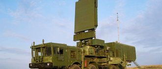
Technical characteristics of the radio relay station
| Frequency range, MHz | 390; 645/1550; 1850 | Minimum separation between transmit and receive frequencies |
| Interval length, km | up to 40-45 | range 390-645 MHz |
| Crew, people | 4 | range 1550-1850 MHz |
| Operating frequency adjustment time, s | 2 | Antenna orientation: Remote, electrically driven in azimuth and elevation |
| Operating mode | continuous |
Radio relay station RRS R-419 “Azid-2”
The radio relay station R-419 is intended for the construction of radio relay communication lines, branching channels from multi-channel radio relay, tropospheric and wire lines, as well as organizing radio inserts into long-distance field cable lines.
Operational and technical characteristics of RRL
| Characteristics | Options |
| Maximum line length, km | up to 300, 90, 20 |
| Average interval length, km | 40-50, 30. 20 |
| Number of rebroadcasts | 6-8, 3, 0 |
| Number of stations at the relay point | 1 |
| Number of low frequency transits | 3 |
| Line capacity | analog |
| Number of standard HD channels | 6, 12, 24, 60 |
| Baud rate (kBit/s) | 48, 480 |
| Number of service channels | 1 |
| Noise immunity of a full-length line, dB | 35 |
| Communication reliability, % of time | 97% |
| Probability of error on a full length line | 10-5 |
Tactical and technical characteristics of the station
Type : mobile, small-channel, VHF, with PRK-FM.
Frequency range : range 2 - 160 - 240 MHz, range 3 -240-320 MHz, range 4 - 320 - 480 MHz. range 5 - 480 - 645 MHz.
Number of fixed frequencies : range 2 - 800, range 3 - 534, range 4 - 800, range 5 - 550.
Frequency grid step : range 2 - 100 kHz, range 3 - 150 kHz, range 4 - 200 kHz. range 5 - 300 kHz.
Characteristics of the transmitting device:
power of the transmitting device for ranges 2, 3 - at least 10 W, for ranges 2, 3 - at least 6 W;
attenuation of spurious radiation from the PRD - no less than 60 dB;
relative instability of the PRD - no more than 5x10⁻⁵.
Receiver parameters:
passband at intermediate frequency: range 2 - 320 kHz, range 3 - 600 kHz, range 4 - 600 kHz, range 5 - 1600 kHz;
real sensitivity - no worse than 4.5 µV (at 5 p/d - 8 µV);
receiver noise figure in the ranges: range 2, 3 - 9 dB, range 4, 5 - 10 dB.
Parameters of the antenna-feeder device:
type of polarization - vertical and horizontal;
antenna type: directional 2B11, antenna gain - 7.5, 9.0, 12.5, 14.5 dB for subbands;
antenna type: omnidirectional 3B12, antenna gain - 2.5 dB (disco-cone);
antenna type: omnidirectional 1B12, antenna gain - 2 dB (pin);
the height of the electrical center of the antenna is 20 m.
Station power supply:
from an industrial network - 3 phase 380V, 50 Hz;
from the petrol-electric unit AB - 4-T/400 - 2 sets;
To power the equipment in emergency mode, 2x10 NKTB-40 batteries are used.
Power consumption - no more than 1.7 kW.
Station deployment time
| Grade | No connection | With connection established |
| Great | 25 | 27 |
| Fine | 30 | 33 |
| Satisfactorily | 35 | 40 |
Crew : - 5 people.
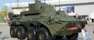
Composition of the station kit
The station is mounted in a K2-131 type body based on the ZIL-131 vehicle. The station includes a set of RRS R-415V.
Station weight - 10050 kg.
Station operating modes
Terminal - for operation via 6 CTCH and SK in two independent communication directions;
External compression mode with six-channel audio equipment (UPL-1) in the range 160 - 645 MHz;
External compression mode with twelve-channel audio equipment (UPL-2) in the range 240 - 645 MHz;
External compression mode with 24 and 60 channel audio equipment in the range 480 - 645 MHz;
External compaction mode by ADF data transmission equipment.
Relays, designed to ensure retransmission of 6 KCH over the group spectrum with the organization of service communications. (Рtr -1)
Retransmission, designed to ensure retransmission of 12 CTCHs over the group spectrum with the organization of service communications. (Рtr -2)
Nodal (UZL) - for branching or relaying any three-channel group of AU, isolating or re-receiving via PM any KFC.
Reception on duty
Operation of the station on a cable, which provides terminal, node and relay modes when operating via PCL;
Automatic functional control without radiation into space.
Tags: military equipment