Wear or swelling of the bore
Wear of the bore is determined by the degree to which the K-2 caliber enters the bore from the muzzle. When the K-2 caliber enters a length of up to 30 mm and the carbine does not meet the requirements of normal combat, the carbine is reamed from the muzzle to a length of 30 ± 1 mm to a diameter of 9 + 0.2 mm.
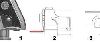
The swelling of the barrel bore is determined by the presence of a shadow transverse ring on its surface. An annular swelling of the barrel (without a metal bulge on the outer surface) is allowed if the carbine meets the requirements of normal combat.
When the barrel is inflated (with the metal convex on the outer surface) in an area located no further than 30 mm from the muzzle, the barrel bore is drilled out to a length of 30 mm with a diameter of 9+0.2 mm.
To do this you need:
♦ install the barrel on the lathe so that the alignment of the barrel bore with the drill clamped in the chuck of the lathe is maintained;
♦ drill out the barrel bore from the muzzle side to a diameter of 8.8+02mm and a length of no more than 31mm;
♦ unfold the drilled part of the barrel bore to the same length using a reamer with a diameter of 9 mm;
♦ use a flat file and sandpaper to clean the traces of swelling flush from the outer surface of the muzzle of the barrel and burrs on the muzzle;
♦ wipe the barrel and oxidize it;
♦ check the action in the assembled carbine.
The main objectives of the Structured Cabling System:
- combine, organize and systematize (unified cable marking) existing networks into a single system with common management;
- provide the ability to change the configuration, expand the scale and functions of the system at minimal cost (from 50 to 50,000 users on an area of up to 1,000,000 sq. m.);
- create a universal medium for transmitting different types of signals (audio, video, information, etc.);
- ensure connection, integration and stable operation of any equipment and standard applications from different manufacturers;
- minimize network administration and maintenance costs;
- increase the reliability, safety, functionality, efficiency and cost-effectiveness of low-current systems;
Before the advent of SCS, these problems were partially solved through the integration of computer and telephone networks, which still operate today, but they are not designed to solve fundamental problems, are less flexible in settings, and have limited capabilities for expanding functionality and scale. Unlike already outdated computer and telephone lines, SCS networks have such advantages
:
- are functional and allow you to customize the system to the individual needs of the User;
- long service life;
- high data transfer rates from 100 Kbps for voice applications to 10 Gbps for information applications
- use several types of transmission media (coaxial cable, UTP, STP, optical fiber);
- transmit different types of signals (audio, video, information, etc.);
- may consist of components from different manufacturers;
- ensure simultaneous operation of several generations of computer networks (as technology improves, there is no need to change cable networks);
- allow you to quickly and economically change SCS connection schemes, create new jobs, without laying additional cable lines;
- make it possible to change the location of users without changing personal data (addresses, phone numbers, passwords, access rights, service classes);
- more convenient and economical to maintain, allow you to identify, localize and eliminate faults in a short time, due to the use of a modular system;
The implementation of structured cabling systems significantly reduces operating costs, increases the speed, quality and security of information exchange and thereby improves employee interaction and has a positive effect on the quality of customer service and the company’s activities as a whole.
Cracks in the receiver cover or fracture (crumbling) of the front hooks of the cover
To eliminate the defect you must:
♦ prepare the receiver cover for welding;
♦ weld the crack in the receiver cover with electrode E50-2.0;
♦ treat welded areas on the receiver cover.
If the front hooks (right or left) are broken or worn, you must:
♦ fuse the defective hook with an EN-20G-4-40 electrode;
♦ process and fit to the receiver so that the pin of the receiver cover fits freely into the hole in the receiver (filing the bevels of the front hooks is allowed, while a ledge is allowed on the left front hook).
Equipment of structured cabling system SCS
The SCS equipment includes cables of different characteristics (coaxial, UTP, STP, optical) and passive switching equipment (telecommunication sockets, crossover and patch panels, couplings, splices, connectors).
Patch panel
(cross panel, patch panel) - is a panel on the front (front) side of which there are connecting connectors, and on the back (rear) contacts for a fixed connection with cables.
The panels differ:
- by type of connectors - fixed (all connectors are of the same type) or stacked (connectors of different types are connected in one housing, for example, copper type 8P8C of different categories, fiber-optic connectors of various types, coaxial, etc.);
- by number of ports - 4, 8, 12, 16, 24, 48, 96
- by shielding - shielded and unshielded;
- according to the mounting method - wall-mounted, rack-mounted (sizes 10 inches, 19 inches, etc.), mounted in intermediate structures, for example a 3U frame;
- by the way the ports are presented - single view and double view (with or without an internal switch)
The choice of panel type is determined by the tasks assigned to the SCS being created. Cable organizers are used to organize the cables coming into and leaving the device.
Telecommunication grounding system
In accordance with the 2002 J-STD-607-A standard, grounding must be installed in all SCS, regardless of the presence of shielded lines. Basics
The purpose of grounding is personnel safety, protection of highways and equipment from the effects of lightning discharges, ensuring balancing of local network transceivers. Telecommunication grounding buses (TGB) are installed in each distribution point near cabinets/racks. The distribution point buses are connected by grounding lines to the main telecommunications grounding bus (GTSGB), installed next to the electrical grounding terminal. Modern standards recommend increasing the cross-sectional area of the grounding line conductor as the length of the line increases. The maximum recommended gauge may be 3/0 AWG or 90 sq.mm. The branches of the main line are made by isothermal welding or permanent connection.
Socket installation options
Power and telecommunication sockets can be installed in boxes, overhead sockets, walls, telecommunication columns, floor hatches.
The photographs show options for placing telecommunication connectors (TP) with power socket blocks. The most common option for creating cable channels is plastic boxes. Walls, office furniture, even ceilings are used to fix boxes. Boxes with a height of more than 80 mm are convenient for placing sockets. Narrow boxes are complemented by wall socket boxes.
Groups of sockets can be marked with markings or the color of the inserts. For example, red inserts are for powering a computer network, white ones are for connecting household electrical appliances.
| Box | Built-in | Hatch | Column |
Telecommunication columns, floor racks, floor hatches are used less frequently. The reason is the higher cost of such solutions.
The cheapest option is built-in sockets. It is also the most aesthetically pleasing. The implementation of this method of installing sockets is optimal when building or renovating an office. An alternative inexpensive option is to install wall socket boxes and lay mini-boxes.
SCS structure
Requirements for the structure, design principles, installation rules, administration, etc. are determined by the international standard ISO/IEC 11801, although in practical application they are not yet considered mandatory; most organizations (especially large ones) try to do everything immediately in accordance with them. Working according to standards makes it possible to unify and facilitate subsequent use and maintenance, expansion and modification of the SCS system.
The SCS structure is understood as a model for constructing a system from functional elements and subsystems. Cables equipped with connectors and laid according to certain rules form lines and highways. Lines, trunks, connection and switching points make up the functional elements of SCS. Three SCS subsystems can be distinguished:
- backbone subsystem of a building complex - connects the cable systems of buildings;
- the main subsystem of the building - connects the distribution points of the floors;
- horizontal subsystem - floor switching system, provides a local network for subscribers, provides access to backbone resources.
Distribution points provide the ability to create a bus, star or ring topology of channels.
The backbone subsystem of a
building
includes the backbone cables of the complex, the mechanical termination of cables (connectors) in the distribution center of the complex and the building distribution center, and switching connections in the complex distribution center. The main cables of the complex can also connect distribution points of buildings.
Trunk subsystem of the building
includes the main cables of the building, the mechanical termination of the cables (connectors) in the building distribution center and the floor distribution panel, as well as switching connections in the building distribution center. The building's main cables should not have transition points, and electrical cables should not be spliced.
Trunk subsystems include information and speech subsystems of SCS. The main transmission medium of the information subsystem is optical fiber, supplemented by symmetrical four-pair cables. If the length of the main line does not exceed 90 meters, symmetrical cables of category 5 and higher are used. For longer lengths, information applications, i.e. computer networks, require fiber optic cables. Building backbone speech applications operate over multi-pair cables. Speech applications that create a telephone network belong to the lower classes of SCS. This allows you to increase the length of the backbone subsystem lines created by multi-pair cables to two to three kilometers.
Horizontal subsystem
includes horizontal cables, mechanical cable terminations (connectors) in the floor switchboard, switching connections in the floor switchboard and telecommunication connectors. No breaks are allowed in horizontal cables. If necessary, one transition point is allowed. All pairs and fibers of the telecommunications connector must be connected. Telecommunications jacks are not administration points. It is not allowed to include active elements and adapters in the SCS. The horizontal subsystem provides a local network for subscribers and provides access to backbone resources. The transmission medium of the horizontal subsystem is symmetrical cables of at least category 5. The SCS standards of 2007 provide for the choice of SCS for data processing centers not lower than category 6. For information technologies (computer plus telephone network) of private homes, the new standards recommend the use of category 6 / 7. Transmission medium broadcast communication technologies (abbreviated VKT: television, radio) of private houses / apartments - symmetrical protected cables with a frequency band of 1 GHz, plus coaxial cables up to 3 GHz. The use of optical fiber is also allowed. The horizontal subsystem is dominated by a computer network. This results in a limitation on the maximum length of the channel - 100 meters, regardless of the type of medium. To extend the service life without modifications, the horizontal subsystem of the SCS must provide redundancy and reserve parameters.
Why you should turn to professionals
The quality and stability of the subsequent operation of the Structured Cabling System directly depends on the parameters laid down during the design of the qualifications of the performers who carried out the installation. A qualified installer, even if he had nothing to do with the project, will always notice the weak points of the project, will definitely inform the Customer and help eliminate them. Often, many nuances separate the initial project from the final result, and in the case of low-current systems this is especially important; only a specialist with extensive practical experience can solve emerging problems, taking into account all the nuances, promptly and with minimal financial, labor and time costs.
The reliability and stability of the system largely depends on the qualities inherent in the design and their implementation during installation. For example, the shorter the length of the channel (and, accordingly, the cable), the lower the signal attenuation and noise level, so it is advisable to shield lines of maximum length. When designing, special attention is paid to the choice of cable category, type of connectors, shielding, etc., laying down the possibilities for system development, scaling and integration with other systems.
High-quality SCS and a reserve of functional parameters ensure long-term trouble-free operation of the local network, which guarantees a quick return on investment and increased efficiency of the organization.