At the end of the 19th century, the Russian Empire was in dire need of effective small arms, the production of which could be quickly launched on its own. During the tests, it was decided to supply the army with a three-line rifle, the creation of the brilliant Russian designer Sergei Ivanovich Mosin.
This “three-line” is now known as the Mosin rifle. And in those distant times, senior management crossed out the name of the inventor, as they modified the original model, adding some solutions from a foreign competing model. But one cannot deny the amazing simplicity and reliability of the resulting “three-line”.
The history of the Mosin rifle
Its design turned out to be so successful that it allowed it to serve the imperial and then Soviet armies until the mid-20th century, even during the Great Patriotic War.
The Russian three-line Mosin rifle is one of the first examples of Russian weapons adopted by the Russian army. Few models of small arms can boast such a rich history of use in military conflicts.
The rifle had its baptism of fire in 1900, when it took part in the suppression of the Boxer Rebellion in China. It was already used quite widely in the Russo-Japanese War, and later on the fronts of the First World War.
The design and quickly expanded production made it possible to create many types of weapons. Over time, the necessary improvements were applied.
Thus, the “three-line” reached the battlefields of the Soviet-Finnish conflict, and then the most difficult, bloody battles of the terrible Second World War. But the history of the creation of such a successful weapon was not simple.
At the end of the 19th century, the Russian Empire began testing its own models of small rifles. At that time, smokeless powder was discovered, which made it possible to change the design of the cartridge, making it more compact and reliable.
Thus began the era of multi-charged weapons.
At the end of all tests, the Russian military leadership had to choose between the two remaining models:
- Belgian repeating rifle designed by Leon Nagant;
- Domestic model of Sergei Ivanovich Mosin.
It must be said that the majority of soldiers and generals gave a clear preference to the foreign model. In fact, Nagant's brainchild was distinguished by high shooting accuracy and a large magazine.
But during the final tests, it misfired twice as many times as the Russian model. Another important quality that determined the future fate of the Mosin rifle, which became a legend, was its relative simplicity and ease of production.
In the Russian Empire, they compromised with the military and introduced improvements to the mass version of the army “three-line”. Now Mosin's weapon received a magazine from the Belgian model.
Because of this, contrary to global trends, the new Russian rifle did not receive the name of the creator, but was simply called a three-line rifle. It became popular among the people as the “three-line” (3 lines according to the old Russian system of measure is 0.3 inches, which is equal to 7.62 mm - the caliber of the new rifle).
The rifle received the name of its creator only when the Soviet leadership decided to rename the most popular small arms in its army. This was in 1930 after a series of modernizations.
However, the prevalence of the “three-line” is also typical for Western countries. It is known that at first Russia could not produce a sufficient number of small arms on its own. To do this, they resorted to the help of French factories.
Also during the First World War, some orders were given to American manufacturers, but the plans were disrupted due to the outbreak of the revolution. Known as the “Mosin-Nagant rifle,” the samples that were not purchased by the Russian side were sold to private owners in the United States.
Rifle production
At the end of the 19th century, most armies of the world had already rearmed and had magazine weapons in their arsenal. The Russian army needed to carry out a large-scale update of its firearms arsenal as soon as possible. That is why, after all the tests were carried out and the sample was approved for mass production, Mosin rifles began to be mass produced in 1892. Three arms factories were engaged in this simultaneously: Sestroretsk, Izhevsk and Tula. But they did not have enough power to quickly provide a huge army, so it was decided to place an order in the amount of 500 thousand rifles from France. The weapons were manufactured by the military factories Manufacture Nationale d'Armes. Before the start of the Russo-Japanese War, the army received more than 3,800,000 guns. After the start of mass production - according to some sources - already in 1893 the rifle was tested in battle against the Afghans in the Pamirs, according to others - in China only in 1900-1901. One thing is certain: already in the early years, designers began to make small changes to the design of the Mosin rifle. A wooden barrel guard was added to the basic configuration, which protected the soldier’s hands from burns; in 1896, for more convenient cleaning of the weapon, the design of the cleaning rod was changed, and in 1910, after the transition to pointed cartridges, the sight was changed.
At the time of Russia's entry into the war, the army had more than 4,500,000 rifles in its arsenal. They were produced in four types: carbine, Cossack, dragoon and infantry. Throughout the war, the country produced more than 3,000,000 more guns and repaired more than 200,000. During these difficult times, there was a huge shortage of weapons, and industrial capabilities did not allow them to produce the required quantity, so the government was forced to buy weapons from foreign companies. The United States ordered the production of 1.5 million Mosin rifles of the 1891-1910 model, but not all of them ended up in Russia, since the US government confiscated some of the weapons after the revolution.
Design and device
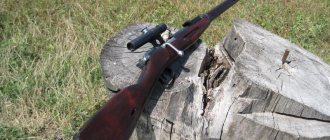
Many technical features of the “three-line” are due to the genius of the great Russian designer - Sergei Ivanovich Mosin. Proof of the simplicity and genius of the weapon is the fact that even now the rifle is successfully used, although mainly for hunting or as collector's items.
S.I. Mosin connected his entire life with the development and production of small arms. Of course, the creation of the rifle that made him famous was not carried out by him alone. But it was this designer who made the most valuable contribution. By the way, he was very upset that his brainchild was not initially named after him.
Mosin was born in the Voronezh region in the village of Ramon. I received a brilliant education. First he studied at the military and artillery school, then at the artillery academy. In 1875, Sergei Ivanovich began his career in Tula, known as the arms capital of Russia.
He quickly became the head of the tool workshop. In 1894, Mosin's genius was noticed, and the designer began to manage an entire plant in the city of Sestroretsk.
Soon he developed a famous rifle for the Russian army. The operation scheme of the “three-line” developed by Mosin was not very complicated.
Many processes were carried out mechanically, so the final model adopted for service was very reliable.
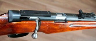
The shutter mechanism is structurally simple. The barrel is rifled, includes 4 grooves running from left to top to right. At the rear of the barrel is the chamber. The factory mark can be found above the chamber. It is usually used to initiate the date of creation of the “three-line” and the manufacturing plant.
One of the key design solutions of the rifle is considered to be a cut-off reflector, which ensured uninterrupted operation of the weapon. The technique Mosin used was a necessity due to the use of outdated rimmed cartridges.
To eliminate snags on the edges of the cartridge cases when feeding the cartridge into the barrel, he used special cut-offs and an original magazine shape.
By the way, English engineers used technology for manufacturing magazines where the cartridges were arranged in a herringbone pattern. This also prevented the cartridges from clinging to each other. It must be said that it was their developments that formed the basis for the production of most small arms of that time.
The “three-ruler” trigger mechanism consists of a trigger and a spring. The bolt sends the cartridge into the chamber, closes the barrel during the shot and ensures the ejection of the spent cartridge case. It consists of a striker and a coil spring.
The rifle used a stepped sight. The stock, consisting of a forearm, neck and butt, was most often made of birch, but in some cases of hazel.
In terms of technical characteristics, many models of that time differed little from each other.
- Caliber - 7.62 mm;
- Weight including bayonet - 4.5 kg;
- Length with bayonet - 166 cm (with bayonet removed 114 cm);
- 4-round magazine.
Debugging a rifle model 1891/30 of the Mosin system
BARREL SELECTION
The barrel is checked using special calibers, and the accuracy of the fire is checked by shooting test batches of cartridges.
Calibers are made for combat barrels ranging in size from 7.60 to 7.68. The caliber pitch is 0.02 mm.
First of all, you need to pay attention to the cleanliness of the barrel. The bore of the barrel must be strictly cylindrical or with a slight narrowing towards the muzzle, and the exit of the rifling on the muzzle of the barrel must be clear and even.
The caliber along the entire length of the barrel must pass smoothly, without delays or failures. If the caliber gets stuck during its passage, this indicates a defective barrel. The calibers are passed one by one until the next one – of a larger diameter – “bites” the muzzle of the barrel.
The surface of the barrel bore should not have traces of rusting, burns, shells and chipped corners along the rifling fields. The presence of small rash and slight rounding of the breech margins is allowed if the weapon shows good accuracy when firing. It is not recommended to select barrels with small rifling, in which, when fired, the bullet casing quickly erases the margins and reduces the size of the combat edge, which ultimately leads to premature removal of the bullet from the rifling. You should also pay attention to the cleanliness of the chamber. The presence of ring scratches and scratches in the chamber will entail a sharp increase in effort when removing spent cartridges. Barrels that have swelling or chafing in the muzzle are completely unsuitable for sniper shooting.
The rifles selected must have a caliber between 7.62 and 7.64.
Initially, we can recommend selecting a rifle using calibers, then the selected ones must be shot at 300 m prone from a rest, and only after that begin debugging. Shooting must be carried out with the best batches of cartridges, in calm weather, under favorable lighting. There is no need to achieve alignment of the midpoint of impact with the aiming point. Accuracy is important. Rifles that provide maximum dispersion within 12 cm are considered suitable. Rifles improve their combat after debugging and will then be quite good...
Shooting must be done in four series of 10 shots. After every two series, the size of the bullet dispersion area is measured. If most of the holes are located in a cluster, but there are individual separations, or if the middle point of impact moves during shooting, then this indicates an incorrect fit of the barrel and receiver in the stock. In these cases, they do not discard the rifle, but debug it and again check the quality of the battle by shooting.
The assessment of the quality of debugging is determined by the stability of the rifle's firing.
Debugging a rifle includes the correct placement of the barrel with the receiver in the stock, debugging the trigger mechanism and adjusting the sights. In addition, the operation of the locking, impact and feeding mechanisms, as well as the ejector, is checked. Inspection and debugging of the rifle is best done in the following sequence:
- inspection and selection of the trunk
- stock selection
- laying the barrel with the receiver in the stock
- descent debugging
- adjusting the sighting device
- debugging of locking, impact and feeding mechanisms
- settlement of the barrel on the stock by firing, installation of the oil seal.
LODGE SELECTION
The quality of the stock and the condition of its wood have a decisive influence on the combat of the rifle. When selecting a stock, dents and cracks are not allowed. The forend with a groove in relation to the stock must be strictly straight, without curvature. Moving the forend to the side at the tip of the forend is permissible in relation to the walls of the barrel by no more than 1 mm. The wood must be straight-grained, with the layers in a parallel direction. The dowel screw should be at right angles to the direction of the barrel. The supporting plane of the dowel screw should not have any irregularities or nicks. Rocking of the forend tip is not allowed. If it is impossible to select a stock made from straight-layer wood, you can take a stock from cross-layer wood, but then the rifle will have to be protected from heavy loads when shooting. Heating the barrel from prolonged shooting causes warping. In this case, the handguard will begin to adhere to the barrel, disturbing its vibration, which will negatively affect the accuracy of the combat.
A walnut stock for older rifles is preferable. This stock, made from good seasoned wood, ensures stability of the rifle. But with skillful selection, an ordinary birch stock provides a fairly good fight.
Having selected the stock (after the barrel has been selected), you can begin debugging the rifle. Before laying the barrel in the stock, the support areas and the fore-end groove must be degreased by washing them with gasoline or turpentine.
PLAYING THE BARREL AND RECEIVER INTO THE BODY
There are several known ways to fit a rifle barrel into a stock:
- with seal
- without contact with the fore-end and the receiver lining (“floating barrel”)
- with a uniform fit of the barrel to the groove of the fore-end of the stock.
The most effective way to improve the combat of a Mosin rifle is to pack the barrel with an oil seal. Since the installation of the oil seal is carried out after shooting the rifle, we will first consider the adjustment of the forend and the supporting planes of the stock. To prevent the barrel from touching the fore-end, you first need to remove the excess layer of wood along the entire length of the fore-end. To do this, you need to disassemble the rifle and select the forend groove with a special semicircular mold or a chisel-scraper 1-1.5 mm in depth and 1 mm on the sides. After this, the barrel and receiver are primed along the entire length, from the bottom and along the side walls, or they are lubricated with an even layer of paint (red lead). Then the barrel and receiver are carefully placed into the stock groove and, connecting the receiver to the magazine, they are tightened with screws. After this, you need to separate the barrel from the stock and, if soot or paint is found at the bottom of the gutter, clean these places. Cleaning should be carried out until the gap on the sides and bottom of the barrel assembled with the stock does not exceed 1 mm. The correct alignment of the barrel position is checked by passing a strip of paper between the barrel and the forend.
The gap between the barrel and the fore-end can be considered normal if the paper runs freely along the entire length of the fore-end from the breech to the end. There should be the same gap between the receiver pad and the barrel as between the stock foreend, i.e. approximately about 2 mm. The barrel lining, tightened with stock rings, should not have longitudinal or transverse displacements. The metal tips of the receiver lining and forend should not touch the barrel. If there is contact, the inside of the tip is filed with a semicircular file. Particular attention should be paid to the correct fit of the receiver in the stock. The receiver must be adjacent to the support pads of the stock without distortion. If the receiver does not touch any platform and is skewed when the screws are tightened, then under such a platform it is necessary to place a gasket made of thin pressed cardboard and thereby achieve a tight fit of the receiver. In cases where the gap between the barrel and the fore-end is larger on one side and the barrel is adjacent to the fore-end on one side when assembling the rifle, you need to align the fit of the barrel with thin cardboard spacers. When placing gaskets at the breech of the barrel, they are layered on the side where the barrel contacts the fore-end and, conversely, at the tail of the receiver, the gaskets are installed on the opposite side of the contact. If the muzzle of the barrel touches the fore-end downward, you need to place a gasket under the breech of the barrel.
The ramrod stop coming out from behind the tree of the gutter support platform is not allowed. When it comes out, you need to screw the tip screw into the ramrod stop and pull it up, after which, holding the stop in a vice, file its upper part with a semicircular file. After filing, put the stop in place.
It is important to ensure that the rear plane of the receiver stop fits well against the support plane of the dowel. The adjustment of the stop to the dowel is carried out after the final adjustment of the barrel with the receiver in the stock. To check, the receiver stop should be smoked, the barrel should be placed in the stock and tightened with screws. The butt plate must be struck several times on a wooden block, and then the barrel must be separated and inspected. Having discovered that the stop does not touch the plane of the dowel, it is necessary to cut grooves 1 mm deep and 0.5 mm wide in the corners of the dowel cutout, then prepare a steel or copper plate in the shape of the cutout, push it tightly into the groove and continue adjusting the stop until it touches completely with dowel. The uneven fit of the stop to the dowel causes a sharp deterioration in the accuracy of the rifle's firing.
The recoil of the rifle from the barrel through the stop and dowel is not felt much when shooting. It is bad if there is no clearance behind the tail of the receiver and the magazine safety bracket (trigger guard) or if the receiver lugs touch the wood of the stock. Then the rifle will, as they say, “fight” when firing.
Therefore, there must be gaps at the junction of the receiver and the stock. The fit of the magazine box to the stock also causes a sharp feeling of recoil. You can restore normal gaps by trimming the wood with a chisel in the places where the receiver and magazine boxes touch the stock.
If, after debugging, recoil is still felt strongly when firing, you need to check whether the screws (rest and tail) are touching the wood of the stock. This contact can be easily detected by looking at the holes in the stock for the passage of screws. There will be marks where the screws touch the wood. They need to be cut down with a round bastard file.
Between the upper edges of the magazine box and the lower plane of the receiver there should be a uniform gap ranging from 1 to 2.5 mm, which is checked from the side of the receiver channel with a specially selected feeler gauge. If there is no gap, the receiver and magazine boxes will not be connected by screws to each other and the stock, which will lead not only to a disruption in the supply of cartridges, but also to an increase in the dispersion of bullets. This defect arises from shrinkage or crushing of the wood of the stock under the square and trigger guard of the magazine box. To eliminate it, it is necessary to make gaskets, bend them slightly to the shape of the groove and place them in the stock in the places where the square and the safety bracket of the magazine box fit. If even when installing gaskets the gap does not meet the required dimensions, you need to increase the number of gaskets. A gap of more than 2.5 mm is unacceptable, since the next cartridge during reloading will not be captured by the bolt cylinder. After all the work done on laying the barrel in the stock, it is necessary to check the correct placement. To do this, alternately tighten both screws (tail and stop) until they stop, then loosen the tail rotor a few turns. The barrel should remain in the same position. This is a sign that the barrel was laid correctly. If, when unscrewing any of the screws, the position of the barrel changes, this means that the barrel and receiver were installed incorrectly.
When debugging a rifle using the second method with a free-fitting barrel, all work is done in the same way, with the exception of installing the oil seal.
DEBUGGING THE TRIGGER
The trigger mechanism of a rifle consists of a trigger, an axle, a trigger spring, and a trigger spring screw.
In practice, several types of trigger release are used:
- short (without stretching), “dry”
- soft (with slight stretch)
- with a warning.
Most often, for accurate shooting, a dry short trigger is used, characterized in that the trigger, when pressed, does not have a noticeable displacement, but as soon as the force applied to it exceeds the tension of the trigger spring, the hammer is released.
The trigger feels soft with a slight pull, when the trigger smoothly yields to the force of your finger, going some way until the trigger is released from the cocking position.
A warning release is characterized by preliminary squeezing of part of the tension of the trigger spring until the trigger stops, after which a slight squeeze of the trigger is required to remove the sear from under the cocking of the hammer.
Before you begin debugging the trigger, you need to check the trigger on the rifle. The check is carried out in the usual way: by slowly pressing the trigger. Defects in the trigger can be identified by feeling the trigger mechanism with your finger.
Disadvantages include:
- vertical movement of the trigger when lowering the sear down, which occurs from wear of the longitudinal groove of the rear part of the receiver at acute angles of engagement of the sear with the cocking of the hammer
- failure of the trigger, i.e. a sharp decrease in the resistance of the trigger to the force of the finger at the moment the trigger is pulled off the sear, as a result of which the finger sharply moves back. The failure of the trigger occurs if the spring part of the trigger spring is too weak and at the same time the exit of the sear into the receiver is too large, as well as when there are sharp angles of engagement of the sear with the cocking of the hammer
- hit on the finger - as a result of the impact of the working edge of the hammer cocking on the trigger slide stop. In this case, a sharp movement of the trigger tail is felt forward.
Having established the defect, you can begin to debug the trigger mechanism. To obtain a short dry trigger, it is necessary to use a trigger spring with a thicker spring part or strengthen it with an additional spring. Debugging should begin with processing the trigger, to do this, use a square file to cut off a semicircular protrusion in the slot of the trigger, which presses on the trigger spring. As a result of filing, the pressure should be applied by the front part of the upper edge of the trigger slot. In case of excessive filing of the hook protrusion, in which the bolt stop does not hold the bolt in the rear position, it is necessary to saw through a groove in the trigger and hammer the liner into it.
To prevent the combat cock from hitting the bolt stop at the moment the trigger is released from the cocking action, you need to lightly file the bolt stop with a round file. A short trigger requires the trigger spring to be fairly stiff. With a high sear height, the trigger spring, under the pressure of the trigger, bends under the large shoulder. To achieve spring stiffness, you need to reduce this shoulder, reducing the size of the sear in height. In order to achieve a certain exit of the sear through the receiver window, it is necessary to ensure the reliability of holding the hammer when cocked. To do this, you should file down the trigger spring stop to 2/3 of its thickness and check whether the trigger is pulled down when the trigger is pulled. If this is the case, then the angle of the reference plane of the sear or cocking of the hammer should be
Change it so that when the sear goes down it does not cause the trigger to move downwards.
Since the combat platoon is hardened, the sear is mainly adjusted and processed. The areas where the trigger spring fits and the hammer is cocked should be polished to a mirror finish. If, when checking the trigger release, the trigger stroke still turns out to be long, then it is necessary to shorten the height of the sear by filing its top with a personal file. If the trigger breaks when closing the bolt - the sear output is small - it is necessary to additionally file the trigger spring stop. Having done this work, check the tension of the trigger release. If the tension is less than 1.5 kg, you should bend the spring part of the trigger spring along (groove).
You need to bend the spring by hitting it with the narrow part of the hammer, placing the spring between the jaws of the vice. Curved in this way, it will become stiffer and increase the tension of the trigger. If it fails, or if the trigger tension is less than 1.5 kg, you can install an additional spring. It will strengthen the main one. An additional spring is installed below the main one; its length should be such that the end of the additional spring rests on the main one in the area where the upper edge of the trigger slot touches. When installing an additional spring, the heel of the trigger spring must be filed down so that the screw can secure both springs. For a short descent, a slight engagement of the combat cocking with the sear is characteristic. But this engagement must be reliable. These conditions can be met if the trigger does not roll in the longitudinal groove of the receiver. To check that the trigger is securely engaged, close the bolt several times with a sharp hand movement.
Closing the bolt is done by pressing the trigger button with the bottom of the palm and touching the handle with your fingers. If, when closing the bolt in this way, the trigger breaks, this indicates that the trigger has a vertical swing in the rear part of the receiver channel. To eliminate pitching, it is necessary to insert a round mandrel into the longitudinal groove of the receiver according to the dimensions of the semicircular part of the trigger. Then, holding the receiver in a vice with copper gaskets, hit the right side of the receiver with a copper hammer and compress it until the box fits snugly against the mandrel.
If, after compressing the receiver, the trigger has a slow motion when moving forward, causing misfires, then you need to clean the right wall of the longitudinal groove with a personal file. Having eliminated this defect, check the shutter operation again in the same way. After making sure that the trigger is securely cocked and the trigger is good both in nature and in tension, you can continue further work.
When debugging a soft trigger with a small pull, you need to follow the same method as when debugging a short trigger with an additional spring, but in this case you need to use the main trigger spring with a thinner spring part. When debugging such a descent, the end of the additional spring should lie on the main spring near the end of the hook slot. When squeezing the trigger, the middle part of the trigger spring will bend, forming a pull even before the sear begins to withdraw from under the cocking action. The clutch angles should be filed in the same way as when setting up a short dry descent. A soft descent with a slight pull can also be achieved due to the large output of the sear into the receiver.
There are two ways to debug a warning descent. In the first, using filing and drilling holes, two protrusions are created in the upper edge of the trigger slot.
The protrusion closest to the sear is used to pre-squeeze the trigger spring, the second protrusion is used to finally remove the sear from under the cocking trigger. The formation of two protrusions creates a noticeable warning when the trigger is pulled. The debugging work is carried out as follows: first, the upper edge of the trigger slot is filed with a personal square file, then a 2.5 mm hole is drilled on the side of the trigger so that it passes immediately under the upper edge of the trigger slot. After the drilling is done, the upper part of the hole is sawed with a round needle file until the desired shapes and sizes of protrusions are formed on the upper edge of the trigger slot. Further debugging is carried out by filing the upper plane of the trigger spring.
The second method of debugging the trigger with a warning is achieved by placing an additional spring above the trigger spring. Both springs are connected to the receiver by the same screw. The upper edge of the trigger slot is filed down (made flat from the inside of the slot). First, they achieve a short descent with one main spring. An additional spring allows you not only to hold the trigger in the desired position, but also when you press it to feel the transition of pressure from one spring to another.
The free play of the trigger is adjusted by deflecting the end of the additional spring. As this downward deflection increases, the travel of the trigger is reduced, and with upward deflection it increases. To improve the operation of the trigger, all rubbing surfaces of the trigger mechanism must be well polished and the entire plane adjacent to each other. The axis of the trigger should sit tightly in the lugs of the receiver so that when the shooter handles the trigger, distortions of the trigger do not occur.
ADJUSTING THE SHUTTER
The bolt is the locking mechanism of the rifle. The combat lugs of the combat cylinder, interacting with the supporting planes of the annular groove of the receiver, directly lock the barrel bore. To achieve better accuracy of combat, it is very important that the supporting planes of the combat cylinder protrusions evenly adjoin the supporting planes of the annular groove of the receiver. When adjusting the combat larva, it is best to use special military calibers (checkers) K14A and K14B. The same calibers check the reliability of locking in cases of gas breakthrough into the receiver.
With one-sided contact of the combat protrusions, the recoil force is distributed unevenly and affects the increase in the dispersion of bullets. To check the tightness of the fit, the supporting planes of the combat lugs of the combat larva are covered with soot. A control cartridge or a K14A checker is sent into the chamber with the bolt. To get more distinct traces of fit, you need to turn the bolt handle two or three times. Then the shutter is removed and the tightness of the supporting planes is determined by the abrasion of the soot.
If necessary, the plane of the combat cylinder protrusion, which has increased dimensions, is cleaned with fine emery cloth, after which the check is repeated. This is done until they achieve a uniform fit of the supporting planes.
During high-speed shooting, it is necessary that the bolt opens and closes easily; this is achieved by carefully grinding the surface of the nipple of the screw protrusion of the trigger and the recess for it on the rear plane of the bolt stem.
If the nipple comes out of the recess of the bolt stem tightly, you need to clean it with a block, removing a minimum layer of metal. This operation must be performed carefully, since excessive shortening of the trigger nipple and rounding of the ridge of the bolt stem recess will lead to arbitrary rotation of the trigger when opening the bolt. The tight rotation of the bolt handle also occurs due to the high resistance of the ejector and reflector springs. To reduce the pressure of these springs, it is recommended to bend them slightly without interfering with the operation of the reflector and ejector.
When adjusting the bolt, you should pay attention to the condition of the bolt stem when releasing the hammer. The correct position of the bolt should be considered when the stem remains motionless at the moment the trigger is struck. It’s bad if the shutter stem shakes. The weapon's stability is compromised. Shooting becomes less accurate. The reason for this drawback is the misalignment of the screw protrusion of the trigger with the screw cutout of the bolt stem. To eliminate it, you need to change the position of the bolt stem by gluing a wooden spacer on the stock, which will limit the downward rotation of the bolt handle. Having finished adjusting the bolt, check its operation by loading and unloading with training cartridges.
Rapid shooting requires loading the rifle very quickly. It is recommended to load the rifle one cartridge at a time, placing the cartridge on the feeder of the feed mechanism and quickly closing the bolt. In order for the cartridge bullet to coincide with the axis of the barrel bore, which eliminates sticking, it is advisable to slightly bend the front end of the feeder upward.
ADJUSTING THE SIGHTING DEVICE
The rifle has an open mechanical sight. Let's focus on adjusting the open sight. The accuracy of aiming at the target depends on the shape and size of the front sight and the slot of the open sight. The greatest aiming accuracy is achieved with a semicircular slot in the aiming bar and a rectangular front sight. The width of the front sight, as a rule, is selected according to the width of the target, equal to 60 cm by 300 m. Taking into account the distance of the front sight from the shooter's eye, the firing distance (300 m) and the size of the target, the width of the front sight is made 2-2.4 mm. The width of the slot is adjusted to the size of the front sight by sawing with a round file, which should allow the sides of the front sight to be clearly seen. The slot is made symmetrical relative to the vertical plane passing through the aiming line.
The width of the slot will depend on the shooter's state of vision and, in some cases, on the color and lighting of the area where the rifle is used. It is better to select the slot width experimentally, focusing on the recommended ratios of 1:2 or 1:3. The shape of the sighting devices should be clearly visible during aiming, without distortion of the lines.
Having finished working with the form, they move on to checking the operation of the sight mechanisms. One of the malfunctions of the sight is the movement of the aiming bar. To determine the swing of the aiming bar, it is necessary to pull the sight clamp back as far as it will go, lower the bar onto the sectors of the block, and swing the bar in different directions. Lateral deflections of the aiming bar under finger pressure are allowed only if it returns to its original position. If this is not the case, you need to select and install a higher axle. When, when pressing on one of the sides of the bar, it does not return to its original position, this indicates a mismatch between the diameters of the axis and the hole of the aiming bar. If it is impossible to select an axis of increased dimensions, you need to make a new one, taking into account the wear of the hole in the aiming block and the bar.
To make accurate vertical adjustments, it is very important that the lower working plane of the clamp lies evenly on both sectors of the aiming block. When one-sidedly touching the plane of the clamp while making corrections vertically, there may be deviations of the average point of impact in the horizontal plane.
To check, you need to place the aiming clamp on any division of the aiming bar and, lifting it, place a sheet of writing paper under the clamp. The lower plane of the clamp should hold the paper on both sectors of the aiming block. If it turns out that the paper is pressed on only one side, it is necessary to file the plane of the aiming clamp with a velvet file until the paper fits snugly against both sectors of the block. The aiming clamp must be firmly held on the division of the aiming bar. To check this, without squeezing the clamp latches, press your fingers alternately on the left and right sides of the clamp where the latches exit. Moving the clamp is allowed provided that it does not overlap the risk of the next division. If the clamp moves excessively, you need to remove it from the sighting bar and check the serviceability of the latches and their springs. If the latch tooth is rounded or chipped, or if the latch springs have settled, these parts should be replaced. If the edges of the cutouts of the sighting bar are rounded or crumbled, it must be replaced.
Next, the tightness of the front sight with the front sight in the groove of the base of the front sight on the barrel is checked. The namushnik should be held firmly enough and at the same time move in both directions from light blows of the hammer. The front sight body is inserted into the groove of the base on the right side.
DRAWING OF THE BARREL ON THE BODY (SHOOTING)
After laying the barrel with the receiver in the stock, debugging the trigger mechanism, adjusting the bolt (installing the sighting device), it is necessary to draft the barrel by firing live ammunition. To do this, you need to separate the barrel from the stock and smoke a thin layer along its entire length, including the receiver and receiver stop. Then carefully insert the barrel into the stock and connect the receiver to the magazine box, tightly tightening the stop and tail screws. The screws must be tightened evenly, moving from one to another. One-sided tightening of first one screw, then the other, can cause the receiver to skew and disrupt the gaps between the fore-end and the barrel.
Before shooting the rifle, to check the tight fit of the lugs of the bolt cylinder to the supporting planes of the annular groove of the receiver, it is necessary to smoke the supporting planes of the lugs with a thin layer. First you need to wipe the annular groove of the receiver dry. After assembling the rifle, you need to check the gap between the barrel and the stock in the area of the forend and the receiver lining. To check, the rifle is positioned horizontally and, by pressing the end of the fore-end up, down, left, right, the size and presence of the gap is checked by the displacement of the fore-end relative to the barrel. The rifle must be fired with live ammunition until the barrel is completely heated, and then check the tightness of the stop and tail screws. As a rule, the screws loosen by 0.5 turns or even more. They need to be tightened, and after that 10-15 shots are fired from the rifle, let the barrel cool and check the gap between the barrel and the fore-end again. The position of the barrel in the forend should not change.
Having ensured that the muzzle of the barrel is in the correct position, you can begin to check the position of the barrel with the receiver in the stock after settling. To do this, you need to unscrew the stop and tail screws and carefully remove the barrel from the stock. Check the support points of the receiver in the stock and the holes for the passage of screws. All places in the stock, with the exception of the support areas, that have traces of soot after settling, must be cleaned with a chisel. Any stuffing in the holes with screws should be removed with a round hog file. Check the fit of the receiver stop to the support plane of the dowel. In the case of a one-sided fit, it is necessary to adjust the stop, as mentioned earlier.
SEALING INSTALLATION
After checking the position of the barrel and receiver in the stock, you need to install a seal on the barrel. The use of an oil seal prevents the fore-end from touching the barrel even in cases of some warping of the stock. The oil seal is a ring made of cloth or woolen material measuring 50x50 mm and is placed on the barrel approximately at the upper stock ring. Before installing it, find the locations of the nodes and antinodes of the vibration of the barrel. To do this, the weapon with the linings removed is secured into the machine, n-shaped clips are placed along the barrel or sprinkled (or whatever). They fire several shots. Under vibration, paper clips, chalk, etc. shift. In places of accumulation, of course, there are nodes, where the paper clips ran away from (i.e., max amplitude) are antinodes. Next, a seal is placed at the identified location of the assembly. The thickness of the seal should fill the gap between the barrel and the forend. To prevent the oil seal from burning out during prolonged shooting due to an overheated barrel, after adjustment, you can lightly lubricate it with thick weapons-grade lubricant. The edges of the omentum are sewn together with threads. Having done this, you need to put the receiver lining in place and, making sure that it is not knocked to the side with the oil seal, secure it with stock rings. If the oil seal moves the receiver lining to any side, you need to clean the inner surface of the receiver lining with a semicircular chisel.
Compilation by Sergei S. Edited September 30, 2000
What cartridges are suitable?
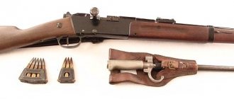
The cartridge for the “three-line” was developed by the Russian engineer Veltishchev. In his work, he used the cartridge for the French Lebel rifle as a basis. The bullet became blunt-pointed and shell-like. The sleeve was distinguished by a protruding bottle-shaped edge. The charge used smokeless powder.
It is interesting that the rim used in the sleeve was already part of an outdated production technology at that time. But the development of the military industry in Russia was at a low level, and the production of such cartridges required less technology.
It was only in 1908 that so-called “offensive” or pointed bullets began to be used for the Mosin rifle. This was preceded by years of foreign intelligence work, because the Germans developed and tested a new type of bullet back in 1905.
After much testing, it became clear that the pointed bullet was a real breakthrough in military affairs, since its performance was almost twice the range and speed of previous models.
Again, the economic component came first here. At first, the budget for innovation was so small that in the factory they changed the geometry of already produced blunt bullets.
The use of new cartridges required a number of upgrades to the existing rifle model. So, in 1910, the army began to receive a “three-line” with an installed Konovalov sight.
Rifle Specifications
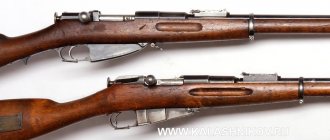
The Mosin rifles that entered service with the Russian army had a huge advantage over their predecessors. The new weapon had a three-line cartridge (7.62 mm) that used smokeless powder. The old single-shot rifles had a caliber of 10.67 mm and used black powder. Over the years, the three-ruler (as the Mosin rifle was popularly called) was modernized several times to improve its use and production. Let's look at two main variants of this weapon.
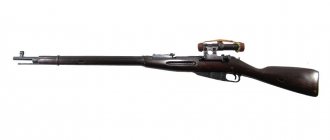
- Model 1891 - Mosin rifle, the characteristics of which are as follows:
- caliber - 7.62 mm (3 lines);
- cartridge - 7.62×54 R;
- length of the rifle with and without a bayonet, respectively, mm - 1734/1306;
- barrel length, mm - 800;
- weight of the rifle with/without bayonet, g - 4300/3990;
- sighting range, in steps - 2700 (about 1900 m);
- initial bullet speed, m/s - 620;
- rate of fire, v/m - 20-35;
- magazine, cartridges - 5.
2. Model 1944 - Mosin carbine, its characteristics are as follows:
- caliber, mm - 7.62;
- cartridge - 7.62×54 R;
- weapon length, mm - 1020;
- rifle barrel length, mm - 510;
- rifle weight, g - 3900 (with fixed bayonet);
- sighting range, m - 2000;
- initial bullet speed, m/s - 810;
- rate of fire, v/m - 20-35;
- magazine, cartridges - 5.
Advantages and disadvantages of the rifle
In 1891 - we can say that this is the date of birth of the Mosin rifle - three types of this weapon were adopted by the Russian army: infantry, dragoon and Cossack “three-line”. They differed from each other in the length of the barrel, and the Cossack version lacked a bayonet. The entire internal structure remained the same.
Like any small arms, the new model also had a number of advantages, but also serious disadvantages.
The “three-ruler” was distinguished by its simplicity and ease of use. Many Russian weapons have always been famous for their reliability. And uninterrupted operation sometimes directly depends on the simplicity of the design.
Mosin's brainchild could be easily disassembled and cleaned, including in the field.
The point of the bayonet was specially made flat to be used as a screwdriver.
It was also easy to assemble. Domestic factories were quickly reoriented to meet new demands, so new small arms were produced in large volumes.
But the “three-line” was not an ideal weapon from the very beginning. The real scourge was the inability to aim effectively. The Russian soldier is, of course, unpretentious, and over time many ideas have appeared that are distinguished by their ingenuity.
But it was in the factory samples that the much-needed front sight was added only before the Second World War, in one of the last modifications of the “three-line”.
The most important disadvantage of the Mosin rifle was the need to always keep the bayonet in a firing position.
Firstly, it was completely inconvenient in limited space. For example, in the trenches or in the forest. The rifle became bulky and inconvenient, constantly clinging to branches or other external objects, which in combat conditions could lead to unnecessary waste of time.
Secondly, the bayonet interfered with aiming. If it was removed in advance (and some fighters did this), then the balance of the barrel was disrupted to such an extent that it became impossible to conduct aimed shooting. In essence, firing turned into shots at random.
Thirdly, with long-term use of the “three-ruler”, the bayonet mount gradually wore out, became loose and again led to imbalance of the barrel. This also had a negative impact on shooting accuracy.
The first samples of the rifle had another bad feature. The top of the barrel was open along its entire length, and the design did not include the use of barrel linings. Only much later did they begin to install wooden pads that protected the soldier’s hands and face from powder fumes, which previously often caused burns.
It is worth noting that the popularity of the improved Soviet rifle was ensured by domestic propaganda. In fact, it was not ideal and did not, as was claimed, surpass many foreign models.
Rifle upgrade options
As mentioned earlier, the Mosin rifle (its photo can be seen below) was adopted for service in 1891. Its main feature was its simplicity and ease of use; it could be disassembled easily and without any tools. The bayonet of the Mosin rifle served as a good and reliable weapon in close combat. In 1910, it had a new sighting frame (suggested by V.P. Konovalov). This change was caused by the earlier transition to pointed bullets, the trajectory of which was slightly different from the trajectory of blunt bullets.
The Red Army used only one type of rifle - the dragoon. After several changes, already in 1930, it began to be called the model of 1891-1930. The rifle has become more convenient, and its production has become much simpler. Firstly, a front sight appeared, and secondly, the shape of the front sight itself changed, which facilitated the process of aimed shooting. Due to the fact that the receiver began to be produced round (previously it was faceted), and the cut-off reflector was assembled from two parts, the production technology was simplified.
In 1931, Soviet snipers also received the Mosin rifle. It was distinguished, naturally, by the presence of an optical sight, a bent bolt handle, and improved processing of the barrel bore. The latest modification of this weapon is the 1944 carbine. But even today, the rifle designed by Mosin has not left the stage: many designers both in Russia and abroad continue to modify this weapon. For example, in the 90s of the twentieth century, the Finns released the SSG-96 sniper rifle, which was based on the three-line rifle. By the way, some versions of these weapons are still considered one of the best in the world today.
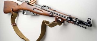
Mosin rifle modifications
The legendary “three-line” was so popular in the Russian and then Soviet army that the appearance of its various modifications is a completely natural phenomenon. Perhaps the most successful improvement to the rifle was the sniper model, which appeared in 1931.
The Mosin sniper rifle allowed targeted fire at a range of 1000-1300 meters. A 3.5x optical sight was installed to help the sniper. The installed optics did not allow constructively to provide a clip for five cartridges, which was installed on all production samples.
So a significant drawback of the sniper version was the ability to conduct only single fire.
After each shot a reload was required.
Only the best soldiers were recruited into sniper squads. After completing training, they received a Mosin sniper rifle, which could be produced in two versions. The first did not involve any improvements to the barrel. In fact, the standard “three-line” was simply equipped with a front sight and optics.
The second option was distinguished by modified characteristics of the intra-trunk space. This allowed for improved accuracy and range. But there were few such samples.
Interestingly, the “three-line” snipers were also equipped with a bayonet, which was attached more tightly and served more as a weighting agent for the barrel. During the tests, it became clear that, indeed, the bayonet in the combat position has a good effect on the accuracy of fire.
During the Great Patriotic War, handicraft modifications were very popular - the so-called sawn-off shotguns of the Mosin rifle. Most often they were used by partisans. They were made easily: they sawed off part of the barrel and butt. The weapon became compact, but the already low shooting accuracy became even worse.
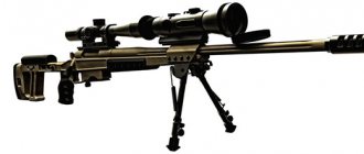
At the end of the 20th century, the armed forces received an order to design a budget sniper model for the needs of the Ministry of Internal Affairs. The Tula residents took Mosin’s famous “three-line” as a basis.
After modernizing the trigger mechanism, adding a cheek and butt, and an additional handle, the result was a compact but inconvenient sniper model. A small batch of these rifles can still be found at the department’s disposal.
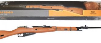
Mosin carbine: model 1944
In 1944, the last modernization of the invention of the designer Mosin was made: the carbine was equipped with a bayonet, which was not removable, but was folding. During the Great Patriotic War, the new improved rifle received its name - “Carbine of the 1944 model”. The weapon was a shortened version of the dragoon version of the Mosin. This carbine was released based on many years of experience in warfare. After the start of production of the 1944 model carbine, the previous version of the rifle was discontinued.
Thanks to its design, the new weapon allowed the infantry to fight better, because in the trenches and thickets it was much more convenient for a soldier with a shortened carbine. Despite some changes, the rifle's firing qualities remained virtually unchanged.
1944 was the last year in the history of improvement of the famous rifle, which went through many wars and conflicts. At the end of World War II, Mosin's inventions were no longer in service with the Soviet Army. They were replaced by SKS carbines and AK-47 assault rifles - you must agree, they are more advanced weapons. The Mosin rifle, however, continued to be in service with several countries of the PRC and the DPRK, Montenegro and Finland.
Myths about “three-rulers”
The most famous and sad myth about the Mosin rifle can be called the history of the Second World War. During the tragic days of the Battle of Stalingrad, the shortage of weapons was so acute that one soldier sometimes received a clip, and another a “three-ruler.”
Later it became known that there were enough weapons, but many warehouses were not far from the border and were captured by the enemy in a matter of days at the beginning of the war. This sloppiness cost the country millions of dead.
Another story connected with the very beginning of the path of the legendary weapon happened with the creator of the rifle, S.I. Mosin. It is known that the French, having learned about some of the wonderful solutions that the designer included in his brainchild, offered him about a million francs for the project.
But Sergei Ivanovich showed patriotism and brought the development to completion, donating the “three-line” to his homeland.
Later, however, it turned out that Mosin himself received only 30 thousand rubles as gratitude. While Nagan, whose clip was added to the rifle, the Russian side paid 200 thousand.
They say that this fact greatly upset the Russian designer. He even wrote letters to management in the hope of receiving at least a commensurate reward, but everything turned out to be in vain.
Interesting facts about the designer Mosin and his rifle
The rifle of Sergei Ivanovich Mosin, despite some of its shortcomings, went down in history as a reliable and inexpensive weapon. But few people know about the many interesting cases associated with its creation. For example, when foreigners learned about the invention, or rather about the rack and pinion magazine, they really wanted to buy this new product. Employees of the company, which was located in France, offered to sell the invention to Mosin for 600,000 francs, and after refusal they gave 1,000,000. But Sergei Ivanovich was a true patriot and refused a huge amount of money. As for Mosin himself, he was interested in weapons since childhood, and in 1875 he headed a tool workshop at the Tula Arms Factory. The designer often participated in various competitions and came up with more and more new inventions. Unfortunately, not all weapons from that time have survived, so much is simply unknown to us. Few people know that the main competition in 1891 for a prototype repeating rifle in Russia was between Mosin and Nagan - two brilliant designers. There are many stories about the victory of our designer, but one thing is known for sure - the Mosin rifle was improved by some of Nagan's developments. The designer wrote to Minister Alexei Kuropatkin that his rifle was taken into service, and his competitor received a large sum of money for the design of the clip - as much as 200,000 rubles, while Mosin was given only 30,000 rubles for all the work. But, despite all the rumors and stories that circulate around the creation of the legendary three-line, it was precisely this model that was manufactured by the Russian designer Mosin, adopted by the government and remained in service for a very long time. Only new models of magazine weapons, which were invented by no less famous designers, for example, Mikhail Kalashnikov, were able to replace it.
The world continues to develop, technologies become more and more accurate. Today there are a large number of automatic weapons, but many believe that it was the Mosin rifle that marked the beginning of many modern inventions. One thing is for sure, Sergei Ivanovich himself and his famous three-ruler have taken an honorable place in history. And this is not surprising, because the designer’s rifle went through several wars and a revolution with our army. Today it is used mainly by hunters because it is inexpensive and quite simple to use.