Mosin rifle 1891/30 Complete disassembly
Mosin rifle 1891/30 Complete disassembly For more than half a century, the Mosin rifle mod. was in service with the Russian and Soviet armies. 1891 and 1891/30 served as the basis for the creation of military carbines mod. 1907, 1938 and 1944, as well as hunting KO-38 and KO-44-1. Detailed demonstration of complete disassembly. During complete disassembly, the wide blade of a screwdriver unscrews the screws: tail, stop and trigger spring, and the narrow blade removes all the rest. Complete disassembly is carried out in the following order: 1. The bolt is separated. To do this, you need to press the trigger with the index finger of your left hand, and open and remove the shutter with your right hand. 2. The cleaning rod is unscrewed and separated. 3. The cover of the magazine box is separated. To do this, press the latch head with your finger, open the cover, squeeze the feed mechanism and remove the cover from the hinge bolt. 4. The bolt is disassembled in the following order: - the bolt is taken in the left hand, the combat cylinder is held with the index finger, and the trigger is pulled with the index and middle fingers of the right hand so that the nipple of the screw protrusion comes out of the recess, and the combat cock does not come out of the fork of the connecting strip, turns to the left and lets go; - the bolt is transferred to the right hand, and with the left hand the stem of the combat larva with the connecting bar is separated by moving forward; — the combat larva is separated from the connecting strip; - the trigger is separated. To do this, the bolt stem is placed vertically, the firing pin rests against the wooden lining with the striker, the mainspring is compressed as much as possible by pressing the left hand on the handle of the bolt stem, and the hammer with the firing pin is screwed with the right hand while the pressure on the handle is gradually loosened and the firing pin with the mainspring is removed; The mainspring is separated from the firing pin. 5. The receiver lining is separated, for which: - the gun belt trench is removed from the upper slot; - unscrew the stop and tail screws two turns; — the springs of the stock rings are pressed and the stock rings are separated by moving them forward; - the barrel lining is separated. 6. The barrel is separated from the stock. To do this, you need to: - place the rifle vertically, grasp it with your left hand, and unscrew the stop screw with your right; - put the rifle on the table, grab the receiver and magazine box with your left hand, and unscrew the tail rotor with your right hand; — separate the magazine box; — separate the barrel from the stock as follows: insert your index finger into the channel of the receiver and separate the barrel. 7. The latch of the magazine box lid is separated. To do this, you need to unscrew the latch screw and remove it by the head. 8. The trigger mechanism is separated and disassembled. To do this, you need to: - turn the barrel with the sight down and, holding the receiver at the cut-off reflector with your left hand so that the sight does not rest against anything, unscrew the trigger spring screw with your right hand; - push out the trigger axis with a drift (you can use a match); — separate the trigger with the spring from the barrel; — separate the trigger spring from the trigger. 9. The reflector cut-off is separated. To do this, you need to: - insert the bolt into the receiver, insert it and turn it to the right to remove the cut-off blade from the receiver slot; — place the barrel with the receiver facing you, and the cutoff-reflector up, and, grasping the receiver with your left hand, unscrew the cutoff-reflector screw with your right; - pressing the thumb of your right hand on the spring part of the cut-off-reflector along its groove, towards the barrel, and slightly lifting the blade by the cut-off tooth, remove the cut-off-reflector, and then separate the blade from the spring part; - remove the bolt stem from the receiver. Assembly is carried out in the following order: 1. The cut-off reflector is inserted into place. To do this, you need to: - insert the bolt stem into the receiver, push it in and turn it to the right; — place the barrel with the cutoff-reflector slit up; — connect the blade to the spring part. This is done as follows: the cut-off reflector is taken by the blade with the right hand, with the heel away from you, and the blade is inserted into the slot of the receiver, and the end of the heel into its groove; — clasp the receiver with your left hand, placing your thumb on the spring part of the cut-off reflector; — press the cutting tooth of the cut-off reflector with the thumb of your right hand; — simultaneously pressing the thumb of your left hand down on the spring part, and the thumb of your right hand forward on the cutting tooth, insert the heel of the cut-off reflector into its groove until the holes for the screw in the heel and in the receiver align; — screw in the reflector shut-off screw; - remove the bolt stem from the receiver. 2. The trigger mechanism is assembled. To do this you need to: - insert the trigger spring into the slot of the trigger; — take the barrel in your left hand by the receiver so that its receiving window is on top; — insert the trigger with the trigger spring into the small window between the ears of the receiver and insert the axle; - holding the trigger spring with your left hand, screw in its screw until it stops. 3. The store box is assembled. To do this, you need to: - holding the magazine box with your left hand with the trigger guard facing you, insert the latch into the slot with the tooth facing the box with your right hand; — holding the latch with your index finger at its head and your thumb at its heel, tighten the sealing screw; — attach the cover of the magazine box with the feed mechanism: — press the feeder with the spring and lever to the cover; — grab the hinge bolt of the magazine box with the cutout of the cover; — release the feeder and close the lid. 4. The barrel and magazine box are attached to the stock. To do this, it is necessary: - supporting the spoon with your left hand from below, insert the barrel with the muzzle into the groove of the forend and, directing the tail of the trigger into its slot, carefully lower the receiver into its socket; — insert the magazine box; - Alternately, in several steps, screw in the screws of the stop and tail until they stop. 5. The receiver lining is attached. To do this you need to: - place the lining on the barrel and slide it all the way into the aiming block; - put on the lower and then the upper stock rings so that the stock spring jumps over the ring. 6. The shutter is assembled. To do this you need to: - put the mainspring on the firing pin; — insert the firing pin with the mainspring into the channel of the bolt stem; - place the bolt stem vertically; - rest the firing pin against a wooden lining and, pressing the bolt stem handle with your left hand, compress the mainspring; — screw the hammer onto the firing pin and, gradually reducing the pressure on the bolt stem handle, carefully insert the screw protrusion of the trigger into the screw cutout of the bolt stem; - Using the cutout of a screwdriver, install the slot on the firing pin against the lines on the trigger button; — with your left hand, put the combat cylinder on the connecting bar tube and turn it to the right until it stops; — with your right hand, insert the firing pin into the channel of the connecting bar tube so that its fork fits into the grooves of the combat cocking, and the nipple of the combat larva into the groove of the comb; — use the cutout of a screwdriver to check the exit of the firing pin; the striker should go into the deep middle cutout (with the number 95) of the screwdriver blade and linger in the shallow cutout (with the number 75); - if there is insufficient or excessive output of the firing pin, separate the firing cylinder and the connecting bar from the bolt stem and screw or unscrew the firing pin using the cutout of the screwdriver blade; - grab the combat cylinder with the index finger of your left hand, and the bolt handle with your thumb, pull the trigger with your right hand and turn it to the right so that the trigger nipple fits into the recess on the bolt stem. 7. The ramrod is inserted into the ramrod track, smoothly lowered and screwed in. 8. The bolt is inserted into the channel of the receiver. To do this, you need to put the rifle with the fore-end on the table and, pressing the index finger of your left hand on the tail of the trigger so that the bolt stop and sear drop into their slots, insert the bolt into the receiver channel with your right hand, push it, turn it to the right and remove your finger from the trigger .
Video of the explosion of Kuzka's mother, the most powerful bomb in history, has been declassified
In 1959, at the exhibition at VDNKh “US Industrial Products,” Secretary General Nikita Khrushchev and then US Vice President (he would become president 10 years later) Richard Nixon argued about the advantages of capitalism and socialism. This debate was called the kitchen debate because the exhibition featured what was then called a “typical American home,” including numerous examples of kitchen appliances.
Politicians argued about many things, but the exhibits themselves spoke of the technical superiority of the Americans. And then Nikita Sergeevich, getting excited, said: “The USSR will soon catch up and surpass the USA in terms of living standards. And he added: “We’ll show you Kuzka’s mother!”
“Kuzka’s mother,” which the USSR would show to the United States, then transformed into a threat.
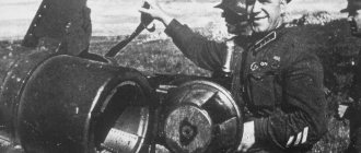
“They really thought it was a new rocket. Because we were making the so-called “Tsar Bomb” of a thousand megatons, which was supposed to blow up half of the globe. And apparently, this is “Kuzka’s mother” - they decided that this was a new weapon. Therefore, the task was even given: to find out about Kuzka’s mother,” recalls the writer, grandson of the USSR Minister of Trade, who was at this exhibition, Alexander Struyev.
The “Tsar Bomba,” which appeared in the USSR only two years later, was called “Kuzka’s Mother” by the Americans.
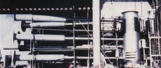
The most powerful bomb in the world in the VNIIEF museum
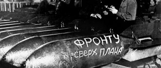
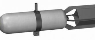
AN602 (aka “Tsar Bomb”) is a thermonuclear aerial bomb developed in the USSR in 1956–1961. a group of nuclear physicists led by Academician of the USSR Academy of Sciences Igor Kurchatov. The Tsar Bomba became the most powerful explosive device manufactured in the history of mankind. The bomb is included in the Guinness Book of Records as the most powerful thermonuclear device tested.
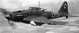
The bomb was tested on October 30, 1961. The Tsar Bomb was dropped from a Tu-95B aircraft at the Sukhoi Nos nuclear test site on the island of Novaya Zemlya. This is exactly what the 40-minute secret film published by Rosatom until August 2022 talks about.
The explosion of the most powerful bomb in history.
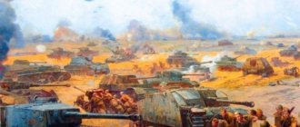
The explosion of AN602 showed results that impressed even its developers:
— The radius of the fireball of the explosion was approximately 4.6 kilometers, the “nuclear mushroom” of the explosion rose to a height of 67 kilometers. — Light radiation could cause third-degree burns at a distance of up to 100 kilometers. — The seismic wave resulting from the explosion circled the globe three times. “Witnesses felt the impact and were able to describe the explosion at a distance of a thousand kilometers from its center. “Ionization of the atmosphere caused radio interference even hundreds of kilometers from the test site for about 40 minutes.
Explosion of the Tsar Bomba on Novaya Zemlya.
The film is interesting even simply for its style - Soviet scientific and educational cinema. They don't make things like that now. The film shows all stages of bomb testing - from the assembly shop to detonation. All this with narrated text and inspiring music.
By the time of this writing, the video had collected more than 1.8 million views.
How do rocket launches work?
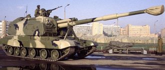
The 2P24 launcher simultaneously performed several tasks - transported missiles to the combat duty point, guided and launched missiles at detected or tracked targets. It could simultaneously transport 2 missiles absolutely ready to hit targets. During start-up, the crew of the machine is inside the SPU.
The missiles were on a boom equipped with hydraulic cylinders, which are responsible for changing the launch angle. The boom itself was part of a support beam, which was fastened to the installation itself by means of cylindrical hinges. When transporting the missiles, they were reinforced with the help of special supports, which were also located on the boom.
Video: Americans tested AK and M4A1 with continuous shooting
Quote, Makc
message No. 33
And when they get to the infantry school, they shoot at at least 350m
No, in the “infantry school” they don’t shoot further than 300 meters, this is a fact and there is no need to make up your own inventions here.
Not everyone, but only selected fighters, are trained in shooting at a distance of over 300 m, up to 600 m no more (!), in a special SDM (infantry sniper) course. At the same time, it would never occur to anyone to use a standard infantry rifle with open sights there - they shoot from numerous specially equipped modifications of the M16 (Mk12 SPR, SAM-R, SDM-R) or SVD analogs converted from the decommissioned M14 (M39, DMR) .
Fire training for US Army personnel.
Fire training from an automatic rifle in the US Army is a continuous process, including the following stages: - initial fire training (BRM - Basic Rifle Marksmanship); - advanced fire training (ARM - Advanced Rifle Marsmanship); — familiarization with the skills of firing in combat conditions (CFF - Combat Familiarization Fire);
Military personnel who show the highest results in individual fire training during advanced fire training and training in firing in combat conditions are sent to train in the course “Shooting as part of a training (tactical) unit” (SDM - Squad Designated Marksman's course). Mastering the corresponding program involves firing at targets at a distance of 300-600 m.
Quote, Makc
message No. 33
Otherwise, why would the M-16 and M-4 have a ring rear sight? And even tuned to as much as 800 meters?
For targeted shooting from an open sight up to a maximum of 400 m, nothing more.
Division "800 m." this is an atavism. Quote, Makc
message No. 33
During an intense battle with frequent changes of location, naturally, it will rarely be possible to aim for a long time
…as the experience of hot spots clearly demonstrates.
American Colonel David Hackworth testifies: “In a sudden collision with the enemy, our soldiers, firing from M-16 rifles, overwhelmingly missed a completely visible and motionless target. Moreover, it did not matter whether the shooting was carried out on the move or from an ambush, the results were almost the same: five misses for six shots. There are hundreds of such cases. The number of misses significantly exceeded the number of hits, despite the fact that the shooting was usually carried out from fifteen meters or less, and in some cases from less than three meters. The shot on the spot became a legend. As for the dependence of the effectiveness of fire on range, in the analysis of six large and approximately 50 small operations there is not a single evidence of when at least one guerrilla or soldier of the armed forces of North Vietnam was killed when firing from M-16 rifles from a distance of more than 60 meters " The Vietnamese experience is fully confirmed by the Afghan one. This is how a GRU special forces officer describes one battle in Afghanistan. On March 16, 1987, a group of nine militants was destroyed. They were fired at, it would seem, in ideal conditions - from top to bottom at an angle of 25-30 degrees from a distance of 50-60 meters. Success factors: moonlit night, the presence of night vision devices and extremely weak enemy opposition due to the surprise of the actions of special forces soldiers. Despite this, each of the scouts spent at least two or three magazines, that is, about nine hundred rounds of ammunition per group, which amounted to a hundred for each “Mujahideen” killed. Characteristically, the battle was not fought by recruits, but by well-trained soldiers; the group included four officers.
I would like to emphasize that both experts spoke about trained fighters.
Main SCADA Components
- Drivers or I/O servers are programs that provide SCADA communication with industrial controllers, meters, ADCs and other information input/output devices.
- A real-time system is a program that provides data processing within a given time cycle, taking into account priorities.
- Human-machine interface ( HMI
, English Human Machine Interface) is a tool that presents data about the progress of a process to a human operator, which allows the operator to control and manage the process. - An editor program for developing a human-machine interface.
- Logical control system is a program that ensures the execution of custom logical control programs (scripts) in a SCADA system. A set of editors for their development.
- Real-time database is a program that saves process history in real time.
- Alarm management system is a program that provides automatic monitoring of process events, classifying them as normal, warning or emergency, as well as processing events by an operator or computer.
- Report generator is a program that allows you to create custom reports on technological events. A set of editors for their development.
- External interfaces are standard interfaces for data exchange between SCADA and other applications. Typically OPC, DDE, ODBC, DLL, etc.
Tu-154. photo. video. interior diagram. characteristics. reviews
Examples of implementations
- Automated process control system for boiler unit st. No. 14 Ufimskaya CHPP-1 branch of OJSC Bashkirenergo
- Automatic control system for turbogenerator st. No. 6 Ufimskaya CHPP-2 branch of OJSC Bashkirenergo
- Process control system for boiler units st. No. 5, 10, 16, 18, 21 FSUE “Siberian Chemical Plant”, Seversk
- Automated process control system for turbogenerators st. No. 10, 13 FSUE "Siberian Chemical Plant", Seversk
- Process control system for boiler units st. No. 4, 5 Samara State District Power Plant, branch of OJSC "TGC-7"
- SAUG boiler unit st. No. 1 of Samara State District Power Plant, a branch of OJSC "TGC-7"
- Automated process control system for boiler unit st. No. 4 Penza CHPP-1 branch of OJSC "TGC-6"
- Automated process control system for hydraulic distribution of Penza CHPP-1 branch of OJSC "TGC-6"
- Automated process control system for boiler unit st. No. 4 CHPP-1 Aktau (Republic of Kazakhstan)
- Automatic control system for turbogenerator st. No. 2 Sormovskaya CHPP branch of OJSC "TGC-6"
- Process control system for stabilization unit AT-3 of JSC RN-Tuapse Oil Refinery
- Automated process control system for desulphurization of the HFC unit of shop No. 6 of Kirishinefteorgsintez LLC
- Process control system for gas fractionation unit of Kirishinefteorgsintez LLC
- Process control system for jet fuels and additive preparation unit for Surgut ZSK
- etc. (see list of implementations)
Specifications
Having analyzed the performance of all vehicles belonging to the complex, we can draw a conclusion regarding the combat effectiveness of the Krug air defense system:
- The maximum speed is 50 km.
- The range of the complex (without refueling) is 300 km.
- Response time is less than one minute.
- Deployment of an air defense system takes less than 5 minutes.
- The range of destruction of an air target is from 11 to 43 km, at an altitude of 3-23.5 km.
- The flight speed of the affected objects is no more than 800 m/s.
But exact data regarding the combat effectiveness of the Krug complex is impossible. The combat use of the equipment has not been declassified to this day. The only thing known is that these air defense systems were used during the Vietnam War and during the improvement of the “Barlev air line” in Egypt.
How to properly put on handcuffs for a 4th grade security guard exam
The person being tested is 1.5 meters opposite the dummy. The rubber stick is suspended on a belt. At the inspector’s command: “Start the exercise!” the person being tested removes the rubber stick from the suspension and strikes the dummy (at least six) in various areas allowed for impact with the rubber stick. After this, the person being tested reports: “I have finished the exercise.”
The employee being inspected is located near the table with protective vests of class 1 and 5. At the command of the supervisor, the inspected employee puts on a protective vest of the specified class and reports: “The protective vest of class 1 (or class 5) is on.” The exercise time is 20 seconds.
Practical part for 4th grade
The employee being inspected is located near the table with protective vests of class 1 and 5. At the command of the manager, “Put on a protective vest of class 1 (or 5),” the inspected employee puts on a protective vest of the specified class and reports: “I have finished the exercise.”
The worker being tested is 1.5 meters opposite the dummy. The handcuffs are on the belt in a case.
At the supervisor’s command “Place handcuffs in front (or behind),” the employee being inspected takes the handcuffs out of the case, approaches the mannequin and puts on handcuffs depending on the task assigned by the supervisor (front or rear). After that he reports: “The handcuffs are on.” Execution time 20 seconds.
4th grade security guard
In addition, exam cards for grade 4 security guards contain questions on current legislation. As part of testing, it is necessary to find out how ready a citizen is to perform the duties of a security guard and apply laws in the course of his activities.
It must be remembered that qualification for category 4 involves the use only of a rubber baton (in extreme cases) or handcuffs, so the questions for the exam by category are similar, but the answers are different. It is necessary to respond due to the given powers to use special means.
Questions of the qualification exam (Practical exercises of the qualification exam) for private security guards of the 4th category
The employee being inspected is located near the table with protective vests of class 1 and 5. At the command of the supervisor, the inspected employee puts on a protective vest of the specified class and reports: “The protective vest of class 1 (or class 5) is on.” The exercise time is 20 seconds.
Positive result: Delivering at least six blows with a rubber stick on the dummy, without touching parts that conventionally correspond to areas of the human body that are prohibited from using rubber sticks on them, within the prescribed time.
Special equipment for security guards, category 4 video
You are an agricultural producer; or perhaps the founder of a gas station; ensure the functioning of air transport or river and sea watercraft. Then this note is for you. We are pleased to introduce you to the AVIOS Company, which is engaged in small-scale and wholesale trade of petroleum products: gasoline, diesel fuel, and kerosene.
The company works exclusively with the largest manufacturers of this product, therefore it guarantees quality in accordance with state standards and market requirements. You will also be pleasantly surprised by the price of the products. The AVIOS company provides acceptance of applications, order formation, and safe, controlled transportation of fuel to the end consumer.
So I repeat once again: The AVIOS company is engaged in small-scale wholesale and wholesale trade of petroleum products: gasoline, diesel fuel, and also kerosene. The company works exclusively with the largest manufacturers of this product, therefore it guarantees quality in accordance with state standards and market requirements.
SAM S-25 Berkut. Range and altitude of damage. Rockets
S-25 "Berkut". In the late 1940s and early 1950s, the Soviet Union began one of the most complex and expensive programs of the early Cold War, second only to its nuclear weapons program. In the face of a threat from the strategic bomber forces of the United States and Great Britain, J.V. Stalin ordered the creation of an air defense missile system controlled by a radar network to repel possible massive air attacks on Moscow. The Moscow system was followed in 1955 by a second program aimed at protecting Leningrad.
Composition of the 2K11 “Krug” anti-aircraft missile system
Control platoon. Compound:
- target detection station - 1 x 1S12;
- target designation receiving cabin - 1 x 9S44 "Crab K-1" (since 1981 it was replaced by 9S468M "Polyana D-1".
Three anti-aircraft missile batteries. Compound:
- missile guidance station - 1 x 1S32;
- self-propelled launcher - 3 x 2P24;
- anti-aircraft guided missile (two for each SP 2P24).
Technical battery. Compound:
- control and testing testing station - 2B9 (several units);
- transport vehicle - 9T226 (several units);
- transport-loading vehicle - 2T6 (several units);
- refueling vehicles;
- equipment for assembling and refueling rockets.